
Related Manuals for Carel c.pco mini IR33 universal


Summary of Contents for Carel c.pco mini IR33 universal
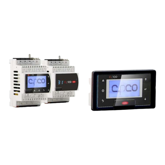
- Page 1 IR33 universal Software for the c.pco Code: SER10IRU0CN User manual H i g h E f f i c i e n c y S o l u t i o n s SER10IRU0CN – rel 1.0 – 19/06/2015...
- Page 2 SER10IRU0CN – rel 1.0 – 19/06/2015...
- Page 3 TUTORIAL: some simple examples to accompany without prior warning. the user in configuring the most common settings. The liability of CAREL in relation to its products is specified in the CAREL general contract conditions, available on the website www.CAREL.com and/or by specific agreements with customers;...
-
Page 4: Table Of Contents
CONTENTS INTRODUCTION .................................... 4 INSTALLATION ....................................5 I/O Configuration..................................5 Panel mounting and dimensions ..............................6 DIN rail mounting and dimensions ............................. 7 Link to other manuals................................. 7 USER INTERFACE ..................................8 Keypad ...................................... 8 Programming ..................................... 8 COMMISSIONING ..................................11 Preparing for operation ................................ -
Page 5: Installation
2. INSTALLATION 2.1 I/O Configuration Analog inputs Description Type Probe 1 NTC, NTC-HT, PTC, PT1000, 4...20mA, 0...10V, 0...5V Probe 2 NTC, NTC-HT, PTC, PT1000, 4...20mA, 0...10V, 0...5V Digital inputs Description Type Digital input 1 ON/OFF Digital input 2 ON/OFF Digital outputs Description Type Digital output 1 (relay) -
Page 6: Panel Mounting And Dimensions
2.2 Panel mounting and dimensions SER10IRU0CN – rel 1.0 – 19/06/2015... -
Page 7: Din Rail Mounting And Dimensions
2.3 DIN rail mounting and dimensions 2.4 Link to other manuals C.pco mini Consult the c.pco manual for details on installing the controller hardware: code +0300021EN. SER10IRU0CN – rel 1.0 – 19/06/2015... -
Page 8: User Interface
3. USER INTERFACE The front panel contains the display and the keypad, made up of 6 buttons, that, when pressed alone or combined with other buttons, are used to program the controller. 3.1 Keypad 3.2 Programming The operating parameters can be modifi ed using the front keypad. Access differs depending on the type: set point, frequently-used parameters (P) and configuration parameters (c). - Page 9 Basics The main menu is the first page the user will see when starting the unit, from the main menu, the information, the setpoint and on/off menu can be selected. In the bottom right corner, the the user can see these menues and switch between these by using the “up” and “down” buttons. To select one of these manues, press the “enter”...
- Page 10 Program menu To enter the program menu, press the “prg” button and enter the password. From this menu, settings corresponding to inputs/outputs, control and operating mode can be changed. Changing I/O parameters In the input/ouput menu the following can be changed. The number of probes used, the type of probes used, the minimum value of the probes, the maximum value of the probe, the offset for the probes, the function of probe 2, the type of output (analog/digital), offset for analog outputs and the number of outputs.
-
Page 11: Commissioning
4. COMMISSIONING 4.1 Preparing for operation operations, before starting the controller check that: Once having completed the installation, configuration and programming • The wiring is performed correctly; • The programming logic is suitable for controlling the unit and the system being managed; •... -
Page 12: Functions
5. FUNCTIONS 5.1 Probes (analog inputs) The probe parameters are used to : • set the type of probe • set the offset to correct the probe reading (calibration) • set the maximum/minimum current/voltage value • activate a filter to stabilise the reading •... - Page 13 Par. Description Setpoint 1 Setpoint 2 0= Direct 1= Reverse 2= Deadzone 3= Direct/reverse from DI1 4= Direct, St1/St2 from DI1 5= Reverse, St1/St2 form DI1 Setpoint differential 1 Setpoint differential 2 Deadzone differential Minimum value of setpoint 1 Maximum value of setpoint 1 Minimum value of setpoint 2 Maximum value of setpoint 2 Mode 1:Direct c0=0...
- Page 14 Mode 2:Reverse c0=1 “Reverse” operation is similar to ”direct” operation, however the outputs are activated when the value being controlled decreases, starting from the set point (St1). When the value measured is less than or equal to St1-P1 (in proportional only operation), all the outputs are activated. Similarly, if the value measured starts rising, the outputs are deactivated in sequence.
- Page 15 Mode 4: Direct/reverse from DI1 c0=3 The controller operates in “direct” mode based on St1 when digital input 1 is open, in “reverse” based on St2 when it is closed. Mode 5: Direct, St1/St2 from DI1 c0=4 The controller always operates in “direct” mode, based on St1 when digital input 1 is open and based on St2 when it is closed. SER10IRU0CN –...
-
Page 16: Validity Of Control Parameters
Mode 6: Reverse, St1/St2 from DI1t c0=5 The controller always operates in “reverse” mode, based on St1 when digital input 1 is open and based on St2 when it is closed. 5.3 Validity of control parameters The parameters that defi ne the operating mode have the validity defined in the table below: Par. - Page 17 Does not apply to analog outputs. Number of outputs To set the number of outputs used (for digital). Press the “prg” button and enter the password, then enter the input/output menu. Then navigate until “nbr of DO” can be seen. This will set the number of digital outputs that will be used to control with the regulator. Var.
-
Page 18: Control
6. CONTROL The controller can operate with two types of control: • ON/OFF (proportional), in which the actuator either operates at full power or is off . This is a simple control mode that in certain cases can achieve satisfying results; •... - Page 19 and tends towards 0. Choosing a differential equal to 2°C (P1=2), a high temperature threshold equal to 40°C (P26=40) and a delay of 30 minutes (P28=30), the operation will be as described in the following fi gure. Independent operation (circuit 1+círcuit2) (c19=2) Setting c19=7 control is “split”...
-
Page 20: Table Of Parameters
7. TABLE OF PARAMETERS Par. Description Type ModB Setpoint 1 Setpoint 2 0= Direct 1= Reverse 2= Dead zone 3= Direct/reverse from DI1 4= Direct, St1/St2 from DI1 5= Reverse, St1/St2 form DI1 Setpoint differential 1 Setpoint differential 2 Deadzone differential Minimum off time of output set as ON/OFF Minimum on time of output set... -
Page 21: Variables
8. VARIABLES Var. Description Type ModBus Di1.Val Value of digital input 1 Di2.Val Value of digital input 1 B1ThAlarmTime Delay for probe 1 value alarm B2ThAlarmTime Delay for probe 2 value alarm B1LowTH Probe 1 lower threshold -999 B1HightTH Probe 1 upper threshold -999 B2LowTH Probe 2 lower threshold... -
Page 22: Alarms
9. ALARMS Alarm Description ModBus Al_retain Error in the number of retain memory writings AoAlarm_1 Alarm on Analog out 1 AoAlarm_2 Alarm on Analog out 2 B1Alarm Alarm on probe 1 B2Alarm Alarm on probe 2 DoAlrm_1 Alarm on Digital out 1 DoAlrm_2 Alarm on Digital out 2 DoAlrm_3... - Page 23 HoldingR 0=0, 1=1, 3=7; USInt Read egister Write HoldingR Minimum value of setpoint 1 Real Read egister 100. Write HoldingR Maximum value of setpoint 1 Real 300. Read egister Write HoldingR Minimum value of setpoint 2 Real Read egister 100. Write HoldingR Maximum value of setpoint 2...
- Page 24 Coil B2Low.Active Low measurement Probe 2 - Alarm Bool Read status Write HoldingR B2ThAlarmTime Time for threshold alarm on probe 2 Read egister Write HoldingR B1ThAlarmTime Time for threshold alarm on probe 1 Read egister Write HoldingR B1LowTH Minimum probe 1 value for threshold Real Read egister...
- Page 25 SER10IRU0CN – rel 1.0 – 19/06/2015...
Need help?
Do you have a question about the c.pco mini IR33 universal and is the answer not in the manual?
Questions and answers