Table of Contents
Advertisement
Quick Links
TRIAX TOUCH WIRELESS SURFACE IMPACT
TESTER
USER'S MANUAL
REVISION 0.9 September 18, 2020
Sales and Technical Support
Alpha Automation, Inc.
127 Walters Avenue
Trenton, New Jersey 08638
United States of America
(V) 609.882.0366
Paul Bamburak
(E)
paulb@alpha-automation.com
Jon Aubel (Technical Support)
(E)
jona@alpha-automation.com
Matt Appleby (Sales)
(E)
matta@alpha-automation.com
Training and Standards
Canadian Playground Advisory, Inc.
1097 West River Road
Cambridge, Ontario N1R 5S5
Canada
Rolf Huber
(v) 647.212.5661 (E)
rolf@playgroundadvisory.com
Advertisement
Table of Contents

Subscribe to Our Youtube Channel
Related Manuals for Triax ASTM F1292

Summary of Contents for Triax ASTM F1292
- Page 1 TRIAX TOUCH WIRELESS SURFACE IMPACT TESTER USER’S MANUAL REVISION 0.9 September 18, 2020 Sales and Technical Support Alpha Automation, Inc. 127 Walters Avenue Trenton, New Jersey 08638 United States of America (V) 609.882.0366 Paul Bamburak paulb@alpha-automation.com Jon Aubel (Technical Support) jona@alpha-automation.com...
-
Page 2: Table Of Contents
Table of Contents Introduction System Components Hand Held Unit “E” Missile Tripod “E” Missile System Use Report Generation PC Application Appendix A: Verification and Calibration Appendix B: Memory Card Appendix C: “A” Missile System Appendix D: Troubleshooting Appendix E: Missile Specifications Appendix F: Critical Fall Height modes Appendix G: Warranties and Representations Appendix H: FCC Rules... -
Page 3: Introduction
1.0 INTRODUCTION The Triax Touch “E” missile system is intended to be used to measure the impact attenuation of surfaces under and around playground equipment in compliance with worldwide standards including but not limited to: ASTM F1292 ASTM F355 En1177... -
Page 4: System Components
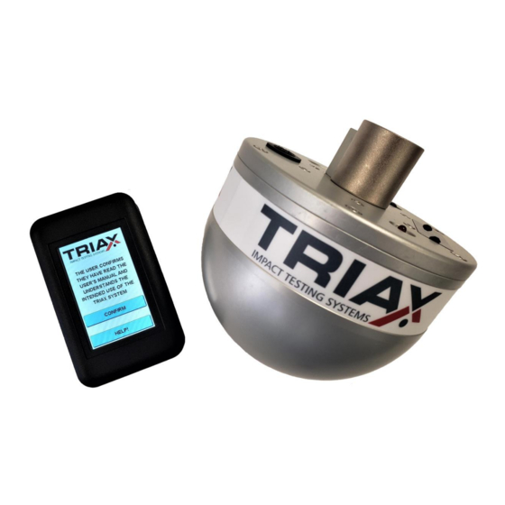
The Triax Touch “E” system consists of the Triax Touch hand held controller, a hemispherical missile and a support tripod. Also included with the Triax Touch “E” system are an 8” x 8” rubber reference pad, battery charger, manual drop handle and fitted carrying cases. - Page 5 The head form is powered by an internal rechargeable NiMH battery. Nickel Metal Hydride (NiMH) batteries are of a lower power density than Lithium Ion batteries thus allowing the Triax system components to be transported by aircraft if required. Typical battery life on a full charge exceeds two months of substantial daily use.
-
Page 6: Hand Held Unit
3.0 HAND HELD UNIT Photo 1 – Triax Touch Hand Held Micro SD Card slot Power push button Photo 2 – Triax Touch Hand Held Side view Photo 3 – Using a pen or pointed object, press the SD card in until it clicks. To remove,... - Page 7 PHOTO 4 – Triax Touch easily fits in the pocket...
- Page 8 The Triax Touch uses wireless communication between the hand held and missile. As shipped from the factory each hand held is paired with a unique missile. A Triax Touch hand held is factory set to pair with both an “E” (hemispherical) and an “A” (cylindrical) missile. After pressing the...
- Page 9 The START key will show up when this is complete and the system is ready for testing The range of the Triax Touch wireless communications is about 20 feet. Should the user try operation beyond this distance the communications between the missile and hand held will cease and the system will appear to be non-operational.
- Page 10 After powering on the Triax Touch hand held and confirming the initial screen, the following screen appears: Press the power button on the head form and it will pair with the hand held. Prepare the drop by pressing START Press RELEASE to release head form from magnet. To save a drop, press SAVE AND NEXT.
- Page 11 3.3 Navigating Menus From any drop, pressing LAST or NEXT will cycle through drops accordingly. Pressing the MENU button will show the following options: SETTINGS: • UNITS: FT—FT/SEC—CM—CM/SEC • RELEASE: TRIPOD (E MISSILE)—TUBE (A MISSILE)—SWING • DELTA: HIDE—SHOW • TIMER: ON—OFF •...
- Page 12 VIEW DROPS Scroll up and down drops by pressing LAST or NEXT. To view the details of a drop, highlight the drop line and press DETAIL. Pressing GRAPH will bring up the graph for the drop...
- Page 13 3.4 Batteries and Charger The Triax Touch hand held and missiles each make use of permanent internal rechargeable nickel metal hydride (NiMH) batteries. Each Triax Touch system is supplied with a battery charger with technology matched to the NiMH batteries used. The batteries in both the hand held and missile requiring charging independently.
- Page 14 To prevent damage to the Triax missiles they should not be used in rain or snow. The Triax missiles should also be stored in dry locations such as a heated office. Storage of the Triax missiles in damp locations such as basements and cellars must be avoided.
-
Page 15: E" Missile
E Missile (HIC tester) -
Page 16: Tripod
5.0 Tripod The Triax Tripod is shown in Photo 3. In addition to the three leg section attached to the top of the tripod, nine snap together sections of legs are provided with the Tripod to allow a maximum drop height of up to approximately 12 feet (drop height is measured from the bottom of the missile to the top of the surface to be tested.) - Page 17 CAUTION! Erecting the tripod can be a hazard due to tipping. To erect the tripod, two persons are recommended. Use of proper head protection is also suggested, as the operating height of the tripod will, in most cases, be above the head of the operators exposing them to the hazard of being struck by either the head form or the tripod.
- Page 18 Properly connected leg section with pin fully extended INCORRECT connection – pin not fully extended Three of the nine leg sections feature a rounded end. These must always be installed as the lowest leg sections when the Tripod is erected. Whenever connecting leg sections the Tripod must first be laid on a horizontal surface.
- Page 19 The locking handle is pressed down gripping the lifting cable and maintaining the height of the missile. Standing to the side the surveyor’s rod (supplied with every Triax E missile system) is used to verify the height of the missile. Fine height adjust can be made by holding the locking device while loosening the lock screw.
- Page 20 5.4 Manual Drop Handle Preliminary testing without setup of the tripod can be conducted using the optional hand held drop handle. The use of the drop handle is shown in photo 6. When using the handle leave the release mechanism set to magnet (see Appendix B.3) Hand Held Drop Handle...
-
Page 21: E Missile System Use
6.1.5 Press the START key. A message will appear on the display indicating that the Triax Touch is being prepared for the drop test. The first time the Triax Touch is turned on after being turned off (or automatically turning itself off) please wait to until START appears. - Page 22 HIC interval. NOTE: At any time while the Triax Touch is preparing for a drop test, the test can be canceled by pressing the GO BACK key. The test will be canceled without changing any test results previously saved in the Triax Touch memory.
-
Page 23: Report Generation Pc Application
7.1 Installation The application is provided in the USERDOCS folder located on the Memory Card supplied with the Triax Touch. It is suggested that this folder be copied to the user’s PC, and an archival copy also be created. Install the Triax Touch host application on a Windows compatible platform by running the SETUP.EXE program supplied in the \USERDOCS\HOST folder. - Page 24 unknown which drop numbers have been data select all 100 drops. The application will attempt to load all 100 drops but will ignore drops for which there is no data. Before clicking Upload, ensure that the location of the memory card and folder shown in the Memory Card Path box is correct.
- Page 25 .DRP file so as to prevent confusion for the user during subsequent testing. The .DRP files do not need to be erased as the Triax Touch hand held controller will overwrite old drop test files with new drop test files.
- Page 26 7.3 Adding individual comments to each drop The report application allows comments to be added for each drop. Typical uses for comments would be to indicate the location on the surface the drop test was made or any observation particular to the specific drop. To add or edit a comment, click once on the desired drop and then hit the ENTER key.
- Page 27 7.4 Adding a report comment To add or edit a single comment to summarize all the drops within a report, double click on the text box immediately below the menu bar. A text box will appear allowing the adding of a new report comment or editing of an existing report comment.
- Page 28 7.5 Viewing Impact Waveforms (Graphs) To view the impact waveform, double click on the desired drop test. 7.6 Archiving Data To archive test data, select Save to Data File under the File menu option. A text box will appear prompting for a file name to which all drop tests currently displayed will be saved as a single file. The files are saved in a proprietary format, with a file extension of .TRW 7.7 Retrieving Archived Data To retrieve test data, select Load Data File under the File menu option.
- Page 29 NOTE: The HIC Interval is a mathematically sophisticated technical detail regarding how the HIC was calculated for a given drop. Some new standards are using the HIC Interval as an added pass / fail criteria but it has not yet found wide use. Most users will want to leave the HIC Interval setting left to HIDE to prevent confusion.
- Page 30 7.9 Calculation of Critical Fall Height – EN1177 Method For critical fall height (CFH) calculation using linear regression analysis (i.e. as per EN1177) four drop tests must be performed, changing the drop height to result in increasing HIC values. The drops are uploaded as described in section 7.2, and selected by clicking on each of the four drops while holding the CTRL key.
-
Page 31: Appendix A: Verification And Calibration
A.2.1 Place reference pad on a bare concrete surface (no carpet or tile, painted is fine) A.2.2 For a Triax Touch E missile erect the tripod and position the missile that the bottom of the missile is 36” +/- ¼” (915mm +/- 5mm) above the surface of the reference mat. - Page 32 A.3 Daily Verification Before subsequent use the of the Triax Touch system the reference pad procedure (three drops at specified height) is to be repeated. The average of the second and third drop must be within +/- 5% of the Initial Reference Pad Averages.
- Page 33 REFERENCE PAD DATA RECORD TRIAX TOUCH Hand Held Computer Serial Number: _________________ TRIAX TOUCH Head Form Serial Number: _________________ TRIAX TOUCH Reference Pad Number: _________________ TRIAX TOUCH Tripod Serial Number: _________________ Date Peak G Temp Comments Initial User Reference Pad Averages...
-
Page 34: Appendix B Memory Card
Triax Touch hand held controller. Several manufacturers offer Memory Cards of varying sizes and the Triax Touch can be used with any card up to and including 32 gigabytes. Memory cards 64GB and above will not work in the Triax Touch due to the EXFAT file systems used on these cards. - Page 35 If the memory card is not inserted into the Triax Touch, or the card is write locked, the user will be warned that no drop test data will be saved. Drop tests can still be performed and the results manually recorded by the user.
- Page 36 With 100 drops in each of ten folders and memory card will hold a total of 1000 drops, requiring approximately 2.5 megabytes of storage. Although not recommended, the remainder of the memory card can be used for storing other user data without hindering operation of the Triax Touch.
-
Page 37: Appendix C: "A" Missile System
Triax Touch “A” MISSILE SYSTEM C.1 General The Triax Touch may be configured for testing of playing field surfaces to ASTM specifications F355 and F1936 using the “A” missile system. The A missile is a stainless steel cylinder, 5.0” in diameter with weight of 20 pounds. - Page 38 NOTE: When using “A” missile guide tubes of 36 inch or 39.4 inch drop heights use the specific height in place of the nominal 24 inch height. Photo C.2 – Base plate attached and ready for use...
- Page 39 LED activity indicator. The black cover protects the charging port when system is in use. The A missile uses the same NiMH battery technology as the Triax Touch hand held, and the specially matched battery charger supplied with the Triax system must be used. The gray push button turns the head form on, and a red LED blinks to show the head form is operating.
- Page 40 Photo C.4 - Trigger block located above release knob C.4 Hand Held Setup Referring to section 3.3 (Settings) of the Triax Touch user manual, set the RELEASE to TUBE. C.5 Performing a Drop Test 1. Using the handle, place the head form in the top of the tube. It will be prevented from falling by a metal pin protruding into the tube about 4"...
- Page 41 5. The display will prompt the user to pull the release knob, allowing the head form to fall and impact the test surface. 6. Upon impact the test results will be displayed. NOTE: Pressing NEXT will save and go to the next drop. Pressing GO BACK will go to the previous screen and save the drop.
- Page 42 8. Refer to the appropriate testing specification to determine the procedure for accumulating test data and averaging test results. C.5 Transporting Guide Tube and “A” Missile To make transporting the system between test sites the “A” missile can be restrained in the guide tube using the supplied locking pin.
- Page 43 Photo C.6 The Triax GMAX system is easily transported to different test sites.
-
Page 44: Appendix D: Troubleshooting
To charge the batteries plug the charger supplied with the Triax system into the charger connector of the component to be charged and plug the charger into an AC outlet. While charging a red LED on the charger will be on. When the battery is fully charged this indicator will become green. -
Page 45: Appendix E: Missile Specifications
APPENDIX E TRIAX MISSILE DIMENSIONS E.1 “E” Missile Weight 10.1 pounds, +/- 0.05 pounds 4.60 kg, +/- 0.02 kg Shape Hemisphere Diameter 6.30 inches, +/- 0.10 inches 160 mm, +/- 2 mm Material 6061-T6 aluminum, solid billet E.2 “A” Missile Weight 20.0 pounds, +/- 0.11 pounds... -
Page 46: Appendix F: Critical Fall Height Modes
APPENDIX F CRITICAL FALL HEIGHT MODES CFH (Critical Fall Height modes) calculate the lowest critical fall height. After data is collected, first order linear regression is used to calculate critical fall height. RULES: The RULES option will appear after a CFH mode is selected, and saved by pressing GO BACK. - Page 47 LOC: Which location user is at. Up to 10 locations available. HGT: Which height user is at. Up to 4 heights available DRP: Which drop user is on. Depending on which mode is selected, 1 drop or 3 drops available.
-
Page 48: Appendix G: Warranties And Representations
The use of this instrument is invalid and not covered by any warranty or any representation should any of the conditions of compliance with ASTM F1292 and / or ASTM F355 in force at the time of manufacture, including, but not limited to periodic calibration, not be performed. -
Page 49: Appendix H: Fcc Rules
APPENDIX H FCC RULES This equipment has been tested and found to comply with the limits for a Class B digital device, pursuant to part 15 of the FCC Rules. These limits are designed to provide reasonable protection against harmful interference in a residential installation. This equipment generates, uses and can radiate radio frequency energy, and if not installed and used in accordance with the instructions, may cause harmful interference to radio communications. -
Page 50: Certificates Of Compliance
Certificate of Compliance TRIAX TOUCH “E” MISSILE The Triax Touch system for surface resiliency testing meets the equipment performance requirements as stated in ASTM F1292-18 04/20/2020 Paul Bamburak, P.E. ● Engineers and Manufacturers ● Electronic Instruments and Controls Precision Mechanisms... - Page 51 Certificate of Compliance TRIAX TOUCH “E” MISSILE The Triax Touch system for surface resiliency testing meets the equipment performance requirements as stated in ASTM F3313-19 04/20/2020 Paul Bamburak, P.E. ● Engineers and Manufacturers ● Electronic Instruments and Controls Precision Mechanisms...
- Page 52 Certificate of Compliance TRIAX TOUCH The Triax Touch system for surface resiliency testing meets the equipment performance requirements as stated in EUROPEAN STANDARD EN-1177:2018 04/20/2020 Paul Bamburak, P.E. 08/20/2015 ● Engineers and Manufacturers ● Electronic Instruments and Controls Precision Mechanisms...
- Page 53 Certificate of Compliance TRIAX TOUCH “A” MISSILE The Triax Touch system for sports surface testing testing meets the equipment performace requirements as stated in ASTM F355-16 04/20/2020 Paul Bamburak, P.E. ● Engineers and Manufacturers ● Electronic Instruments and Controls Precision Mechanisms...
- Page 54 Part 15 Subpart C “Intentional Radiators” modular approval in accordance with Part 15.212 Modular Transmitter approval. TRIAX IMPACT TEST SYSTEM The Triax Impact Test System contains FCC ID: T9J- RN42 This device complies with Part 15 of the FCC Rules.
Need help?
Do you have a question about the ASTM F1292 and is the answer not in the manual?
Questions and answers