Table of Contents
Advertisement
Quick Links
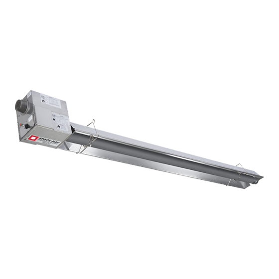
INSTALLATION AND OPERATION INSTRUCTIONS
INFRARED RADIANT POULTRY/SWINE TUBE HEATER
Single and Two Stage Push Through System (Positive Pressure)
OWNER / INSTALLER: For your safety this manual must be carefully and thoroughly read and understood before
installing, operating or servicing this heater. This heater is intended for use with either Natural Gas or Propane
Gas. It must be installed by a qualified service person or a licensed contractor in accordance with state and local
codes. In the absence of these codes, the installation must conform to the National Fuel Gas Code ANSI Z223.1
(latest edition), also known as NFPA54 or the Natural Gas and Propane Installation Code CSA B149.1 in Canada.
▲WARNING: Improper installation, adjustment, alteration, service, or maintenance can cause property damage,
injury or death. Read the installation, operation and maintenance instructions thoroughly before installing or
servicing this equipment. For assistance or additional information, consult a qualified installer, service agency or
the gas supplier.
INSPECT all combustion air openings into the building and, if necessary, clear as they become blocked by litter,
dust, feathers or other matter.
FOR YOUR SAFETY: Exhaust fans MUST be operating on an appropriate cycle when heaters are operating to
avoid a high concentration of carbon monoxide. When used without fresh air, this heater may give off carbon
monoxide, an odorless and poisonous gas. CARBON MONOXIDE POISONING MAY LEAD TO DEATH. Early signs of
carbon monoxide poisoning resemble the flue with headaches, dizziness and nausea. If you experience these
signs, GET FRESH AIR IMMEDIATELY! Have the heaters serviced as soon as possible and check the ventilation in
the house.
These heaters are designed for agricultural applications and may operate with the use of either Natural Gas or
Liquid Propane (LP) Gas. Check the heater's nameplate to determine the correct gas type before proceeding
with installation.
!INSTALLER: This manual is the property of the owner. Please present this manual to the owner when you leave
the job site.
IF YOU SMELL GAS:
! DO NOT try to light any appliance.
! DO NOT touch any electrical switch; DO NOT use any
telephone in your building.
! IMMEDIATELY call your gas supplier from a neighbor's
telephone. Follow the gas supplier's instructions. If you
cannot reach your gas supplier, call the fire department.
Scan warranty QR code on the right to
register your product.
!IMPORTANT: SAVE THIS MANUAL FOR FUTURE REFERENCE.
SPACE-RAY
Post Office Box 36485 (28236) • 1700 Parker Drive (28208) • Charlotte, North Carolina
Phone (704) 372-3488 • Fax (704) 332-5843 • www.spaceray.com • email: info@spaceray.com
THE DEFENDER Models:
PCA-SS 75 (N5,L5,N7,L7
PCA-SS 100 (N5,L5,N7,L7
PCA-SS 125 (N5,L5,N7,L7
PCA-SS 150 (N5,L5,N7,L7
FOR YOUR SAFETY
DO NOT store or use gasoline or other
flammable vapors and liquids in the vicinity of
this or any other appliance.
Form 43343110
May 2021
Advertisement
Table of Contents
Troubleshooting

Related Manuals for Space-Ray PCA-SS 75


Summary of Contents for Space-Ray PCA-SS 75
- Page 1 INSTALLATION AND OPERATION INSTRUCTIONS INFRARED RADIANT POULTRY/SWINE TUBE HEATER Single and Two Stage Push Through System (Positive Pressure) THE DEFENDER Models: PCA-SS 75 (N5,L5,N7,L7 PCA-SS 100 (N5,L5,N7,L7 PCA-SS 125 (N5,L5,N7,L7 PCA-SS 150 (N5,L5,N7,L7 OWNER / INSTALLER: For your safety this manual must be carefully and thoroughly read and understood before installing, operating or servicing this heater.
-
Page 2: Table Of Contents
TABLE OF CONTENTS SECTION DESCRIPTION PAGE 1.0) Safety ..............................2 2.0) Installer Responsibility ........................2 3.0) General Information ........................... 2 4.0) Minimum Clearances to Combustibles ................... 4 5.0) Specifications............................5 6.0) Packing List ............................6 6.1) Accessory Packages .......................... 9 7.0) Typical Assembly Layouts –... -
Page 3: Safety
1.0) SAFETY This heater is a self-contained infrared radiant tube heater designed for use in poultry applications. Safety information required during installation and operation of this heater is provided in this manual and the labels on the product. The installation, service and maintenance of this heater must be performed by a contractor qualified in the installation and service of gas fired heating equipment. - Page 4 Although these heaters may be used in many applications other than space heating (e.g., process heating), Space-Ray will not recognize the warranty for any use other than space heating. This heater is not an explosion proof heater. Where the possibility of exposure to volatile and low flash point materials exists, it could result in property damage or death.
-
Page 5: Minimum Clearances To Combustibles
NFPA54 requires that the installer must post signs that will “specify the maximum permissible stacking height to maintain the required clearances from the heater to combustibles.” Space-Ray recommends posting these signs adjacent to the heater thermostat or other suitable location that will provide enhanced visibility. -
Page 6: Specifications
9 ft. * MOUNT HEATERS AS HIGH AS POSSIBLE. Minimums are shown as a guideline for human comfort and uniform energy distribution for complete building heating applications. Consult your Space-Ray representative for the particulars of your installation requirements. Model Identification:... -
Page 7: Packing List
6.0) PACKING LIST PCA-SS Burner Package Ref. Part # Each Control Package Includes: Qty. See chart. Burner Box Assembly (Refer to the following chart for Package Part Numbers) 43343110 Installation and Operation Manual -not shown- 42907040 Control Fastener Kit - comprising of: 02189020 Screw, #10 x 1/2”... - Page 8 BURNER PACKAGE NUMBERS SINGLE STAGE CONTROLS TWO STAGE CONTROLS MODEL NO. PART NO. GAS TYPE MODEL NO. PART NO. GAS TYPE PCA-SS 75-N5 44165250 NATURAL PCA-SS 75/50-N7 44165750 NATURAL PCA-SS 100-N5 44165270 NATURAL PCA-SS 100/65-N7 44165770 NATURAL PCA-SS 125-N5 44165290...
- Page 9 A. PCA (Aluminized Steel System) Body Package Descriptions (Package Part Number is indicated on the outside of each corresponding carton.) 20Ft. 30Ft. 40Ft. 50Ft. Systems System System System System 20 Ft. pkg 30 Ft. pkg 40 Ft. pkg 50 Ft. pkg PCA Body Packages –Aluminized 44055210 44055320...
-
Page 10: Accessory Packages
6.1) ACCESSORY PACKAGES A. End Reflector Accessory Package, Part #43341010 (1 pkg. per Straight Configuration Series) Contains: End Reflector, #43320000……QTY–2 Speed Clips, #02266010……QTY–8 B. Exhaust Hood Package, Part #42924100 Contains: Exhaust Hood Assembly, #30779000……QTY–1 #8-18 x ½ Self-Drilling Screws, #02189030……QTY–2 C. - Page 11 F. Kit, 2-Stage Relay Board, Part #44195000 Contains: Relay Board , #30709058……QTY–1 Enclosure, #30709059……QTY–1 Cord Connector – ½” , #30635040……QTY–2 G. 4” Vent Cap, Part #30297040 (for use on heater VENTED) H. 4” Flue Collar Adapter, Part #30504500 (for attachment to flue vent pipe) Form 43343110 -10- May 2021...
-
Page 12: Typical Assembly Layouts - Straight Configuration
7.0) TYPICAL ASSEMBLY LAYOUTS – STRAIGHT CONFIGURATION EMITTER LENGTH 2 Ft. Turbulator MODEL Min. Max. Sections PCA-SS 75 20 Ft. 30 Ft. PCA-SS 100 30 Ft. 40 Ft. PCA-SS 125 30 Ft. 40 Ft. When installing a Defender series heater into a barn with stalls or partitions, we recommend using a model that is no longer than 40 ft. -
Page 13: Dimensions - Straight Configuration
7.1) DIMENSIONS – STRAIGHT CONFIGURATION (48” HANGING CENTERS) Form 43343110 -12- May 2021... -
Page 14: Heater Assembly / Joining Of Tube Sections
7.2) HEATER ASSEMBLY / JOINING OF TUBE SECTIONS Form 43343110 May 2021 -13-... -
Page 15: Typical Suspension Methods
6. Heaters must not be supported by gas or electric supply lines and must be suspended from a permanent structure with adequate load capacity. Space-Ray recommends that the body sections be suspended using chains with turnbuckles. This will allow slight adjustments after assembly and heater expansion/ contraction during operation. - Page 16 Consult your Space-Ray Representative if you have any questions prior to the installation concerning particulars of your application.
-
Page 17: Assembly Of Tube Sections
9.0) ASSEMBLY OF TUBE SECTIONS During field assembly of the heater body sections, the recommended procedure is as follows: 1. Before hanging heater sections, first determine the actual layout of the system (see Section 7.0 for details). Consideration must also be taken for flue pipe, fresh air ducting, gas piping, clearances to combustibles, etc. before hanging heater. -
Page 18: Assembly Of Extension Section
9.4) ASSEMBLY OF EXTENSION SECTION See typical assembly overview (Section 7.1) for typical complete assembly. Assemble additional extension sections as required for all systems. (See Section 7.0) for typical layout details. Join the tube sections together and secure with tube couplings as described below: The following coupling tightening instructions MUST be followed properly to ensure the integrity of the tube connections. - Page 19 4. Slide the next tube into the coupling. 5. Make sure both tube ends are butted together. 6. Finish tightening both bolts to 40-60 ft./lbs. torque to ensure a complete seal. 7. Use the two Self-drilling screws through the pre-punched holes to secure the tubes in the coupling. 8.
-
Page 20: Inserting Turbulators
9.5) INSERTING TURBULATORS 1. Assemble the turbulators together by interlocking the slotted end portions. Slide these into the last tube section until they are flush with the tube end. Note: Refer to the table below for quantities of turbulators required for each heater model. MODEL 2 Ft. - Page 21 Form 43343110 -20- May 2021...
-
Page 22: Attaching Burner Box Assembly
10.0) ATTACHING BURNER BOX ASSEMBLY 1. Attach the burner box and gasket to end of tube flange and secure with 1/4-20 locknuts. 2. Assemble the optional end reflector flush with the end of the main body reflector. Secure by sliding speed clips onto the reflector edges. -
Page 23: Connecting The Tiss System
10.7) CONNECTING THE TISS SYSTEM Description: The TISS (Tube Integrity Safety System) is designed to shut the main burner off in the event that a burnout occurs in the first 10ft. section of firing tube. Note: When replacing the firing tube a new TISS wire assembly PN 44176510 (spring and spring retainer clamp not included) must also be installed. - Page 24 3. Hold the spring retainer clamp and pull the TISS wire assembly to end of reflector at overlap joint. Slide spring retainer clamp over end of reflector as shown. Step 3 4. After attachment of the TISS, check to make sure that there is sufficient tension on the wire. Follow the diagram below to increase or decrease the tension as necessary.
- Page 25 ANGLE MOUNTED HEATERS ONLY 5. If heaters are to be angle mounted, the TISS wire holder clamp must first be re-positioned as shown using the bottom hole pattern of the clamp. Follow procedures described earlier for all other adjustments. Step 5 Failure to re-position the wire clamp at the bottom hole pattern will shorten the life expectancy of the TISS wire assembly.
-
Page 26: Gas Connections And Regulations
11.0) GAS CONNECTIONS AND REGULATIONS IMPORTANT BEFORE CONNECTING THE GAS TO THE HEATER 1. Connect to the supply tank or manifold in accordance with the latest edition of National Fuel Gas Code (ANSI Z223.1), and local building codes. Authorities having jurisdiction should be consulted before the installation is made. - Page 27 US ONLY: Connector MUST be installed in “” configuration. Use only the 36” long connector that was furnished with this heater. US ONLY: A gas connector certified for use on a tubular type infrared heater per the standard for Connectors for Gas Appliances, ANSI Z21.24/CSA 6.10 is supplied for installation in US only.
-
Page 28: Instructions For Pressure Test Gauge Connection
12.0) INSTRUCTIONS FOR PRESSURE TEST GAUGE CONNECTION SUPPLY PRESSURE 1. The installer will provide a 1/8” N.P.T. tapped plug, accessible for test gauge connection immediately upstream of the gas supply connection to the heater. OUTLET GAS PRESSURE CHECK AND ADJUSTMENTS Gauges that measure pressure in pounds per square inch are not accurate enough to measure or set the manifold pressure. - Page 29 Figure 1 TO ADJUST REGULATOR (two stage gas valves): Turn on power and energize main gas valve solenoid. Do not energize the HI solenoid. Remove regulator cover screw from the low outlet pressure regulator (see Figure 2 below) and turn screw ...
-
Page 30: Electrical Connections
GAS PRESSURE TABLE SUPPLY PRESSURE MANIFOLD PRESSURE GAS TYPE High Low (2-stage only) Minimum* Maximum Natural Gas 3.5” W.C. 1.4” W.C. 5” W.C. 14” W.C. Propane Gas 10.0” W.C. 4.0” W.C. 11” W.C. 14” W.C. *Minimum permissible gas supply pressure for purpose of input adjustment. 7”... - Page 31 M.8) SINGLE STAGE (N5/L5) INTERNAL AND THERMOSTAT CONNECTIONS SINGLE STAGE CONTROLS - INTERNAL CONNECTION WIRING DIAGRAM SINGLE STAGE CONTROLS - SCHEMATIC WIRING IGNITION MODULE TERMINAL DESIGNATIONS DIAGRAM 24VAC/R 24 VAC Supply to Module TH/W Thermostat Input PS/W Pressure Switch Input System Ground Valve Power Valve Ground...
- Page 32 SINGLE STAGE CONTROLS - THERMOSTAT WIRING DIAGRAMS SINGLE STAGE CONTROLS LINE VOLTAGE (120V) THERMOSTAT CONNECTIONS – SINGLE HEATER J. LINE VOLTAGE (120V) THERMOSTAT CONNECTIONS – MULTIPLE HEATERS Form 43343110 May 2021 -31-...
- Page 33 K. LOW VOLTAGE (24V) THERMOSTAT CONNECTIONS – SINGLE HEATERS L. LOW VOLTAGE (24V) THERMOSTAT CONNECTIONS – MULTIPLE HEATERS (utilizing a fan center relay) M.9) TWO STAGE (N7/L7) INTERNAL AND THERMOSTAT CONNECTIONS TWO STAGE CONTROLS - INTERNAL CONNECTION WIRING DIAGRAM Form 43343110 -32- May 2021...
- Page 34 TWO STAGE CONTROLS - SCHEMATIC WIRING IGNITION MODULE TERMINAL DESIGNATIONS DIAGRAM 24VAC/R 24 VAC Supply to Module TH/W Thermostat Input PS/W Pressure Switch Input System Ground Valve Power Valve Ground 120/240 VAC Input (Hot) Blower Output TWO STAGE CONTROLS - THERMOSTAT WIRING DIAGRAMS TWO STAGE CONTROLS Form 43343110 May 2021...
- Page 35 A. LOW VOLTAGE (24V) THERMOSTAT CONNECTIONS – SINGLE HEATERS B. LOW VOLTAGE (24V) THERMOSTAT CONNECTIONS – MULTIPLE HEATERS Form 43343110 -34- May 2021...
-
Page 36: Recommended Thermostat Sensor Location
C. LOW VOLTAGE (24V) 3 WAY MANUAL SWITCH CONNECTIONS – MULTIPLE HEATERS 13.1) RECOMMENDED THERMOSTAT SENSOR LOCATION The thermostat sensor should be located approximately 10ft from side of the heater as shown in Figure 1 and at distances from burner box as shown in chart of Figure 2 below. Ideally this should also be located between the feed and drink lines. - Page 37 Figure 1 Figure 2 When installing a Defender series heater into a barn with stalls or partitions, we recommend using a 40 ft. unit or shorter. This is due to the natural characteristic of all tube heaters. Which is they have a significant temperature drop past 40 ft.
-
Page 38: Venting
Maximum vent length ft. Model exchanger intake length ft (4” fresh air and vent ft. (4” diameter) length ft diameter) (4” diameter) PCA-SS 75 PCA-SS 75 PCA-SS 100 PCA-SS 100 PCA-SS 125 PCA-SS 125 PCA-SS 125 PCA-SS 150 PCA-SS 150 Note: 1. - Page 39 SINGLE HEATER VENTING (VERTICAL THROUGH THE ROOF) 1. When venting the heater to outside of building through a roof, use single-wall metal pipe. This is to be constructed of galvanized sheet metal or other approved noncombustible corrosion-resistant material as allowed by state or local codes. 2.
- Page 40 6. A minimum clearance of 6 inches must be maintained between the outside wall and vent cap (18” clearance will provide stability under high wind conditions). 7. The horizontal venting system shall not terminate: • Less than 4 ft. (1.2m) below, 4 ft. (1.2m) horizontally from or 1 ft. (30cm) above any door, operable window or gravity air inlet into any building.
-
Page 41: Air For Combustion
15.0) AIR FOR COMBUSTION If indoor combustion air is to be supplied for a tightly enclosed area, one square inch of free area opening shall be provided below the heater for each 1,000 Btu/hr of heater input. When outside air is used, the opening below the heater shall be one square inch of free area for each 4,000 Btu/hr of heater input. -
Page 42: Air For Combustion - Through Ceiling
15.2) AIR FOR COMBUSTION – THROUGH CEILING If the heater is installed less than 2 ft. from the ceiling, a flexible transition section must be used to allow for expansion/contraction of straight tube heaters. Install the fresh air intake assembly (supplied in accessory Kit no. 44129500) shown below. - Page 43 Alternate method for installing the Cold Air Stopper. The Cold Air Stopper (supplied as accessory) can be installed directly into the fresh air intake start collar instead of the flexible air intake hose as shown above. 1. Remove the fresh air intake from the burner control unit shown in Step A. 2.
-
Page 44: Air For Combustion (Hog Barn)
15.3) AIR FOR COMBUSTION (HOG BARN) Non-contaminated air for combustion MUST be ducted to the heater in all agricultural applications. DO NOT take combustion air from pressurized attic spaces, with the exception of broiler houses. Locate the air intake away from contaminant sources. Use caution when locating air intake above curtain walls, as they can leak. -
Page 45: Lighting And Shutdown Instructions
16.0) LIGHTING AND SHUTDOWN INSTRUCTIONS 1. Turn on the gas and electrical supply. 2. Set the thermostat to call for heat. The blower motor will energize. 3. Ignition should occur after the 15-second pre-purge. 4. If the burner fails to light, or flame is not detected during the first trial for ignition (a period of approximately 15 seconds) the gas valve is de-energized and the control goes through an inter-purge delay of approximately 60 seconds before another ignition attempt. -
Page 46: Sequence Of Operation - Two Stage (N7/L7)
Note: When the heater is operated by a thermostat interrupting the line voltage (120V) to the heater then the post purge function is disabled. If the flame is not sensed during sequence T3 then the burner will automatically begin re-ignition sequence T2. The ignition sequence will be repeated three times with a 60 second inter-purge. -
Page 47: Cleaning And Annual Maintenance
18.0) CLEANING AND ANNUAL MAINTENANCE This heater must be cleaned and serviced annually by a qualified contractor before the start of each heating season and at any time excessive accumulation of dust and dirt is observed. Maximum heating efficiency and clean combustion will be maintained by keeping the heater clean. -
Page 48: Troubleshooting Guide - Single Stage (N5/L5)
19.0) TROUBLESHOOTING GUIDE – SINGLE STAGE (N5/L5) Form 43343110 May 2021 -47-... - Page 49 TROUBLESHOOTING GUIDE – SINGLE STAGE (CONTINUED) Form 43343110 -48- May 2021...
- Page 50 TROUBLESHOOTING GUIDE – SINGLE STAGE (CONTINUED) Form 43343110 May 2021 -49-...
-
Page 51: Troubleshooting Guide - Two Stage (N7/L7)
19.1) TROUBLESHOOTING GUIDE – TWO STAGE (N7/L7) Form 43343110 -50- May 2021... - Page 52 TROUBLESHOOTING GUIDE – TWO STAGE (CONTINUED) Form 43343110 May 2021 -51-...
- Page 53 TROUBLESHOOTING GUIDE – TWO STAGE (CONTINUED) Form 43343110 -52- May 2021...
-
Page 54: Replacing Parts
20.0) REPLACING PARTS Only use genuine Space-Ray replacement parts. Parts are available from the factory for replacement by a licensed person. Refer to the Replacement Parts Guide in Section 22.0) for all replacement parts. 20.1) REMOVAL OF MAIN BURNER AND ELECTRODES The main burner can be inspected without removing the burner housing from the heat exchanger tube. -
Page 55: Removing Gas Valve And Manifold Assembly
20.2) REMOVING GAS VALVE AND MANIFOLD ASSEMBLY 20.3) AIR SWITCH PRESSURE CHECK Form 43343110 -54- May 2021... -
Page 56: Ignition System Checks
4. Turn heater on and wait until blower motor is activated. 5. Observe air pressure from manometer. This should be higher than the set point indicated below for correct operation. Model Operating Pressure PCA-SS 75 0.70” W.C. Hot PCA-SS 100 0.80” W.C. Hot PCA-SS 125 0.39”... -
Page 57: Installation Data
IGNITION MODULE DIAGNOSTICS Flame Fault If at any time the main valve fails to close completely and maintains a flame, the full time flame sense circuit will detect it and energize the combustion blower. Should the main valve later close completely removing the flame signal, the combustion blower will power off following the post purge period. -
Page 58: Replacement Parts Guide
22.0) REPLACEMENT PARTS GUIDE BURNER BOX Item No. Part No. Description Qty. Fasteners 02295040 PHTCS #6-32 x 3/8" 02266010 Speed Clips (for air inlet plate) 02261030 HHTCS #8-32 x 3/8" (green coated) 02242050 PHTCS #8-32 x 3/8" 02242070 PHTCS #8-32 x 1/2” 02123170 RHMS #8-32 x 3/4"... - Page 59 42744069 Air Sensing Tube Asm. (90 deg bend) 1/4" 30635050 Cord Connector 1/2” #M4521 (Gray) 30635049 Nut ½” #8463 (Black) 30635040 Cord Connector ½” #M3200 (Black) 03988100 Plastic Vacuum Air Tube 10" (P2- to static pressure point) 03988100 Plastic Vacuum Air Tube 10" (P1+ to total pressure point) 43563040 Supply Cord Set (SVT-1 18/3 x 72"...
- Page 60 Note: 1) Screws, Nuts and Washers are standard hardware items and can be purchased at any local hardware store. 2) Please order by PART NUMBER – not by Item Number. 3) Replacement Part Prices are available when ordering. 4) Please refer to complete Model Number when ordering. ALL ILLUSTRATIONS ARE INTENDED TO GIVE THE GENERAL IMPRESSION OF UNITS ONLY.
-
Page 61: Warnings Card
23.0) WARNINGS CARD Copies of this card may be ordered at no charge under part no. 43344990 for installation near the heater. Form 43343110 -60- May 2021... - Page 62 No Representative is authorized to assume for the manufacturer, any liability except as set forth above. For the name of your nearest distributor in case of claim under this warranty, contact: Space-Ray Poultry Heating Products / Gas-Fired Products, Inc. / 1700 Parker Drive, P.O. Box 36485 / Charlotte, NC 28236 / Phone: (704) 372-3488 / Fax: (704) 332-5843 / email: info@spaceray.com.
Need help?
Do you have a question about the PCA-SS 75 and is the answer not in the manual?
Questions and answers