Table of Contents
Advertisement
Quick Links
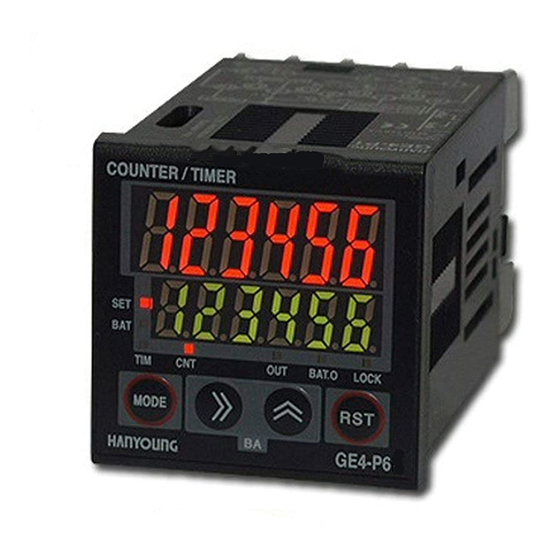
Counter / Timer
GE Series
INSTRUCTION MANUAL
Thank you for purchasing HANYOUNG NUX CO,.Ltd. Product.
Please check whether the prouduct you purchased is the exactly
same as you ordered. Before using product, please read
instruction maunal carefully.
Safety Information
Before you use, read safety precautions carefully, and use this product
properly. The precautions described in this manual contains important
contents related with safety; therefore, please follow the instructions
accordingly. The precautions are composed of DANGER, WARNING
and CAUTION.
DANGER
Do not touch or contact the input/output terminals because they may
cause electric shock.
WARNING
1. If there is a possibility of an accident caused by errors or
malfunctions of this product, install external protection circuit to
prevent the accident.
2. This product does not contain an electric switch or fuse, so the user
needs to install a separate electric switch or fuse externally. (Fuse
rating : 250 V 0.5 A)
3. To prevent defection or malfunction of this product, supply proper
power voltage in accordance with the rating.
4. To prevent electric shock or devise malfunction of this product, do
not supply the power until the wiring is completed.
5. Since this product is not designed with explosion-protective
structure, do not use it at any place with flammable or explosive gas.
6. Do not decompose, modify, revise or repair this product. This may
cause malfunction, electric shock or fire.
7. Reassemble this product while the power is off. Otherwise, it may
cause malfunction or electric shock.
8. It you use the product with methods other than specified by the
manufacturer, there may be bodily injuries or property damages.
9. Due to the danger of electric shock, use this product installed onto a
panel while an electric current is applied.
CAUTION
1. The contents of this manual may be changed without prior notification.
2. Before using the product you have purchased, check to make sure
that it is exactly what you ordered.
3. Check to make sure that there is no damage or abnormality of the
product during delivery.
4. Do not use this product at any place with corrosive(especially
noxious gas or ammonia) or flammable gas.
5. Do not use this product at any place with direct vibration or impact.
6. Do not use this product at any place with liquid, oil, medical
substances, dust, salt or iron contents. (Pollution level 1 or 2)
7. Do not polish this product with substances such as alcohol or benzene.
8. Do not use this product at any place with excessive induction
trouble, static electricity or magnetic noise.
9. Do not use this product at any place with possible thermal
accumulation due to direct sunlight or heat radiation.
10. Install this product at place under 2,000m in altitude.
11. When the product gets wet, the inspection is essential because
there is danger of an electric leakage or fire.
12. If there is excessive noise from the power supply, using insulating
transformer and noise filter is recommended. The noise filter must
be attached to a panel grounded, and the wire between the filter
output side and power supply terminal must be as short as possible.
13. If gauge cables are twisted closely, the effect on noise may occur.
14. Do not connect anything to the unused terminals.
15. After checking polarity of terminal, connect wires at the correct position.
16. When this product is connected to a panel, use a circuit breaker or
switch approved with IEC847-1 or IEC947-3.
17. Install the circuit breaker or switch at near place for convenient use.
18. For the continuous and safe use of this product, the periodical
maintenance is recommended.
1381-3, Juan-Dong, Nam-Gu Incheon, Korea
HEAD OFFICE
TEL: (82-32)876-4697 FAX : (82-32)876-4696
19. Some parts of this product have limited life span, and others are
changed by their usage.
20. The warranty period for this product including parts is one year if
this product is properly used.
21. When the power is on, the preparation period of contact output is
required. In case of use for signals of external interlock circuit, use
with a delay relay.
Model and Suffix code
Model
GE
GE3
GE4
Appearance
GE6
GE7
P
Type
T
4
Digit
6
1
Stage
2
A
Power supply
D
Power Supply
During the first 100
after power input and first 200
opening, it is consider as ascend and descend time of internal power and
external output power. Therefore, it does not operate during unstable
period in order to prevent from malfunction which is caused by unstable
output operation of external sensor
Supply signal only after 100
Supply power only after 200
Dimensions & Panel Cutout
GE7
GE4
MA0106E081216
Description
Digital Batch Counter
S(W)96.0
(H)48.0
(L)107.6
(W)48.0
(H)48.0
(L)84.0
(W)72.0
(H)36.0
(L)81.0
(W)72.0
(H)72.0
(L)87.0
PRESET BATCH
TOTAL (Indicator)
4 : 9999 (4 digit)
GE3,GE7:Not available
6 : 999999 (6 digit)
1 stage
2 stage
Twin timer Support
100 V - 240 V a.c
24 V - 60 V d.c
after power
following the power input.
following the power shutdown.
[Unit : mm]
Advertisement
Table of Contents

Related Manuals for HANYOUNG NUX GE Series


Summary of Contents for HANYOUNG NUX GE Series
- Page 1 MA0106E081216 Counter / Timer GE Series INSTRUCTION MANUAL Thank you for purchasing HANYOUNG NUX CO,.Ltd. Product. Please check whether the prouduct you purchased is the exactly 1381-3, Juan-Dong, Nam-Gu Incheon, Korea HEAD OFFICE same as you ordered. Before using product, please read TEL: (82-32)876-4697 FAX : (82-32)876-4696 instruction maunal carefully.
-
Page 2: Connection Diagram
Connection Diagram NPN Input GE4-P1 Panel Cutout GE4-P2 +0.7 +0.6 +0.5 +0.5 66.5 Same as Same as +0.5 +0.5 above above More than More than More than More than More than Same as Same as More than above above Specification Model GE6-P1 Power... -
Page 3: Name Of Each Section
GE3-P2 GE7-P1 Coefficient display (RED FND) Display coefficient value (counter), time process value (timer), batch coefficient value and setup list. Setup display (GREEN FND) Display setup value (counter), setup time (timer), batch setup value, instant GE7-P2 output setup (batch setup is 0 in Timer) and setup contents SET1, SET2 (SET), BAT Indicates the status of coefficient section and setup section (BAT lamp corresponds to batch status.) - Page 4 Counter Mode Setup Method Counter input operation mode ‘A’ needs value greater than min signal width, B need value greater than half of min signal width. Convert Operation Mode to Function Counter Function Setup Mode Mode -> Press MD key for 2 seconds Setup Items Contents Initial value...
-
Page 5: Input Connection
Counter Output Action Mode One Shot Output of OUT1 Output Select One Shot Output between As for 1 Stage Counter (OUT), it is the same as 0.01ms~99.99ms 2ND Output (OUT2) Action. Self-Maintenance Output Self-Maintenance Output One Shot Time Delay One Shot Output of OUT2 Output Post Count Up Action Coefficient value indication is maintained and setting up HOLD (0) leads to self-maintenance output. -
Page 6: Output Connection
Input Logic Setup Status can be Indicated Time Range verified in Function Setup Mode. Range Selection 6 digits Time Range 4 digits Time Range Internal Impedance is 4.7 , and switches over to Pull Up or Pull Sexagecimal Sexagecimal Decimal Decimal DOWN Down from NPN/PNP Selection. - Page 7 Interval / Signal START Signal START / ON delay Runs when START (CP2) is ‘ON’. Run when START (CP2) is ‘ON’ within the initial setup value Output is ‘ON’ during the set time, and the indicated value is initialized and When setup time exceeds, display value will maintain and output (one short output is ‘OFF’...
-
Page 8: Batch Counter
Signal RUN Power RUN - ON delay Runs when Power is ‘ON’ ON Output for T1 Time / OFF for T2 Time. Repetition Initializes and stops when Reset is ‘ON’ Runs when START (CP2) is ‘ON’, and resets when START (CP2) is ‘OFF’ Set Time is first to be reduced during Down Mode Setup.