
Subscribe to Our Youtube Channel
Related Manuals for Schwank MonsterFan Series


Summary of Contents for Schwank MonsterFan Series
- Page 1 Use Instruction Schwank GmbH ▪ Bremerhavener Str. 43 ▪ D 50735 Cologne Tel: +49 (0)221-7176-0 Fax: +49 (0)221-7176-288 www.monsterfans.com info@monsterfans.com Language: English Date: 01/2021 Revision: v1.4...
-
Page 2: Table Of Contents
Table of content: Introduction ......................3 Specifications ......................3 Safety Instructions..................... 3 Placement & Distances ..................4 Checklist ........................ 5 Parts Overview MonsterFans ................... 6 Bill of Materials ...................... 6 Required Tools ....................... 8 Installation & Mounting .................... 8 Safety Clearances ....................8 Safety Distances to Ventilation Systems ............. -
Page 3: Introduction
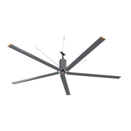
Introduction Congratulations on your MonsterFan purchase. The High Volume, Low Speed fans (HVLS) of the MonsterFans series are energy-saving units with high comfort and diameters from 3.6 m (12ft.) to 7.3 m (24 ft.). They move big amounts of air at low rotational speed. The blades are streamlined and ideally engineered according to the principles of aerodynamics. -
Page 4: Placement & Distances
All electrical components are pre-programmed at the factory and ready for use. Follow these installation instructions during installation. Please do not make any changes to components. Install the device completely before putting the device into operation. To avoid the risk of electric shock, note the following: a) Use this device only as intended by the manufacturer. -
Page 5: Checklist
2.2 Checklist ☐ Do you have the right mounting set for your mounting position? The standard mounting set supplied with this fan for I-beam, allows the fan to be hung on steel beams. Do not mount the fan on a purlin or a framework. If you are unsure, please contact customer service. -
Page 6: Parts Overview Monsterfans
Parts Overview MonsterFans 1. Steel structure 2. Safety rope ring 3. Steel structure fastening 4. Extension tube 5. Motor housing 6. Winglets of fan blades 7. Fan blades 8. Turnbuckle & clamps 9. Safety steel rope 10. I-type safety adapting piece 3.1 Bill of Materials www.monsterfans.com info@monsterfans.com... - Page 7 Bill of Materials - MonsterFans 1. Motor Housing 2. Top-Plate 3. Spacer 4. Beam clip 5. Turnbuckle 4x 6. I-type fan 7. Fastener M5 x 12 mm 8. Bottom plate & 1x replacement blade retainer 5x 9. Safety steel rope 10.
-
Page 8: Required Tools
3.2 Required Tools Spanner Set Socket Wrench Screwdriver Spirit Level Wire rope Cross & Slot shear Cable Shears Wire Stripper Multimeter Distance Meter Threadlocker Glue Please also note the necessary safety precautions for the use of a scissor lift and the general safety precautions. -
Page 9: Safety Distances To Ventilation Systems
4.2 Safety Distances to Ventilation Systems If the air supply outlet of a ventilation system is below the blades, a minimum distance of 1 times or larger the fan diameter from the blade tip is sufficient. If the air supply outlet of a ventilation system is located above the blades, a minimum distance of 2 times or larger the fan diameter from the blade tip is necessary. -
Page 10: Mounting Sets
4.4 Mounting Sets The fans are usually connected to an I-beam Accordingly, this element as standard is included in every packaging unit. Standard Mounting Set (for I-Beam) Article no 19580220 Weight: 14 kg Optional mounting set for concrete structure Mounting Set concrete structure Article no. -
Page 11: Extension Elements
4.5 Extension Elements The MonsterFans fans are delivered ex-works with a hanging element of standard 1m. Optionally, we offer another 1 m and 2 m extension element and a connection piece to connect two extension elements. The max. length of these extension elements must not exceed 3 m consisting of max. 2 elements. -
Page 12: Installation Of Monsterfans
4.7 Installation of MonsterFans Start by installing the mounting element on the ceiling. Attachment of the suspension & extension element Pull your electrical cable through the extension tube. Then attach the safety steel rope (parts list no 9) and secure it with the steel wire lock (no 10). Observe the notes on wire rope clamp connections. - Page 13 Note: The safety steel ropes must be aligned symmetrically for the same load, then tightened evenly, use the turnbuckles and a threadlocker glue at the end. Connect the motor supply cable to the motor terminal box. Observe the instructions in chapter 4.8 Electrical connections.
-
Page 14: Electric Connections
Now wire the cable to the Controller box. Use your own electrical cable for this. Now install the Controller Box. We recommend installing it at a height of approx. 1.6 m. The 3-pole switch disconnector (parts list no. 20) must be mounted and integrated in the direct vicinity of the Controller Box. -
Page 15: Oil Check And Oil Safety Pin
To connect the motor please remove the MonsterFans cover from the motor housing above the motor terminal box and unscrew the cover from the motor terminal box. Lead the motor connection cable through the EMC gland and pay attention to the position of the shielding braid. -
Page 16: Frequency Inverter
After proper cabling and checking, you can turn on the power. The area around the fan must be free of obstacles. Start with a test run of 10 minutes. If the operation of the fan works properly, instruct the operator and please use the handover protocol for a formal handover. -
Page 17: Commissioning
Commissioning 6.1 Test Run Ideally, test the fan for 10 minutes to see if there is any unusual noise, vibration from the device or from the safety steel ropes. Also make sure that the fan runs safely with a sufficient safety distance to all possible obstacles. -
Page 18: Frequency Inverter Error Messages
6.4 Frequency Inverter Error Messages www.monsterfans.com info@monsterfans.com... -
Page 19: Warranty & Maintenance
Warranty & Maintenance Our quality assurance applies to the entire fan. The warranty period begins on the date of acceptance by the customer after professional installation and commissioning. This ends with the statutory warranty period. The following causes are not covered by the warranty: 1. -
Page 20: Packaging Units
Packaging Units A MonsterFan is delivered in two wooden boxes. Picture: Wooden Box Fan Blades Picture: Wooden Box Motor Type Diameter Dimensions Weight Total MF-C24 7.3 m (24 ft.) Box Motor: 180 kg 950 mm*830 mm*520 mm 307 kg Box fan blades: 3700 mm*420 mm*450 mm 127 kg MF-C20... -
Page 21: Acceptance Report For Installation & Commissioning
Acceptance Report for Installation & Commissioning Customer Date Street Service techn. Postal code Order No. Contact Person Phone E-Mail Cell phone Product type (s) No. of Fans Serial no. Hub height RCD usage Kind of RCD Adjustment of Special conditions frequencies Verification by Customer Yes ☐... -
Page 22: Acceptance Report Of Maintenance
10 Acceptance Report of Maintenance Customer Date Street Service techn. Postal code Order No. Contact Person Phone E-Mail Cell phone Product type(s) No. of Fans Annual Maintenance Year 1 Year 2 Year 3 Year 4 Year 5 (Tick Boxes Accordingly) 1. -
Page 23: Declaration Of Conformity
11 Declaration of Conformity www.monsterfans.com info@monsterfans.com... - Page 24 Schwank GmbH - Bremerhavener Strasse 43 - D-50735 Cologne Tel: +49 (0)221-7176-0 Fax: +49 (0)221-7176-288 www.monsterfans.com info@monsterfans.com www.monsterfans.com info@monsterfans.com...
Need help?
Do you have a question about the MonsterFan Series and is the answer not in the manual?
Questions and answers