Table of Contents
Advertisement
Quick Links
Advertisement
Table of Contents

Subscribe to Our Youtube Channel
Related Manuals for Analytic Systems VTC610R Series

Summary of Contents for Analytic Systems VTC610R Series
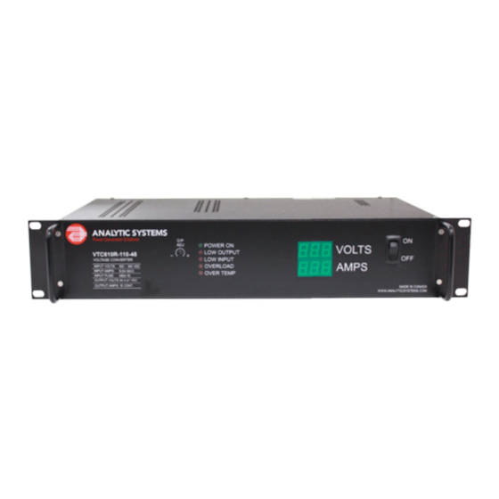
- Page 1 INSTALLATION & OPERATION MANUAL VTC610R SERIES Voltage Converter...
- Page 2 Never allow battery acid to drip onto the voltage converter. Medical Equipment Notice Analytic Systems does not recommend the use of their products in life support applications where failure or malfunction of this product can be reasonable expected to cause the failure of the life support device or to significantly affect its safety or effectiveness.
-
Page 3: Specifications
Introduction The model VTC610 Voltage Converter supplies 12, 24, 32 or 48VDC from a 110, 250 or 300 VDC power source. The all-new Current Mode switching design offers increased power and reliability in a compact package. Extra input and output filtering reduce EMI to extremely low levels. - Page 4 General Switching Frequency 60 ± 2 KHz Idle Power < 10 Watts Noise on Input < 50 milli-Volts Noise on Output < 50 milli-Volts Transient Response < 2V for 50% Surge (Output Amps/2) Efficiency > 85 % @ maximum output Temp.
-
Page 5: Installation
Installation MOUNTING Mount the unit in a DRY location. Allow at least 4 inches of clearance around it for adequate cooling. POWER CONNECTION The unit is supplied with power leads about 3 feet long. This should normally be adequate to connect to a source of power. -
Page 6: Operation
Operation Turn the switch on the front of the unit on to energize the outputs. The green ‘Output On’ indicator light will glow to indicate the proper operation of the unit. OUTPUT ADJUSTMENT The unit has an adjustment potentiometer to allow up to ±1.0V adjustment of the output voltage. -
Page 7: Battery Backup (Optional)
Battery Backup (Optional) The Battery Backup Option allows the unit to switch to using a connected battery as a power source in the event of external power failure. The DC power output normally supplies the load while the battery is maintained at full charge by a 1A trickle charger built into the unit. -
Page 8: Troubleshooting
Troubleshooting This unit provides LED indicators and a buzzer to help diagnose any problems. The unit should sound the buzzer to alert you prior to shutting itself down. You should immediately check the indicators to determine the cause of the shutdown. LOW OUTPUT Indicates that the output voltage is below normal because: The current demanded by the devices connected to the unit exceeds the... -
Page 9: Limited Warranty
2 Years from date of manufacture for non-standard or OEM products 1 Year from date of manufacture for encapsulated products. 3. Analytic Systems will determine eligibility for warranty from the date of purchase shown on the warranty card when returned within 30 days, or...
Need help?
Do you have a question about the VTC610R Series and is the answer not in the manual?
Questions and answers