Table of Contents
Advertisement
Quick Links
Advertisement
Table of Contents

Subscribe to Our Youtube Channel
Related Manuals for HBM FS64


Summary of Contents for HBM FS64
- Page 1 Installation Guide English FS64 Tilt Sensor...
- Page 2 Portugal Tel. +351 229 613 010 Fax +351 229 613 020 fibersensing@hbm.com www.hbm.com/fs Mat.: 7-2002.4263 DVS: A4263-3.5 HBM: public 05.2015 Sensor Design Version: v2.1 E Hottinger Baldwin Messtechnik GmbH. Subject to modifications. All product descriptions are for general information only.
-
Page 3: Table Of Contents
........2.3.6 Locking the Sensor for Transportation ......FS64 A4263-3.5 HBM: public... - Page 4 ......... . . Temperature Effect on the Sensor ......FS64 A4263-3.5 HBM: public...
-
Page 5: Technical Details
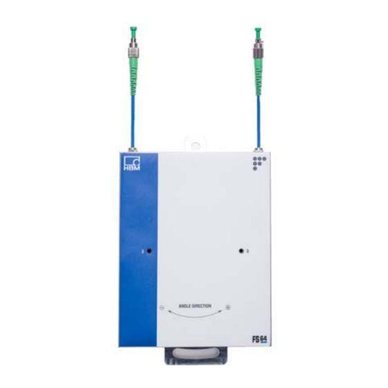
FS64 - Tilt Sensor • Outdoor • NC 1.1.1 Overview The FS64 - Tilt Sensor is a Fiber Bragg Grating (FBG) based sensor, designed to measure small variations of angle towards the vertical. The sensor uses two FBGs in an innovative push-pull configuration for effective temper... -
Page 6: Applications
Based on the measurement of an absolute parameter - the Bragg wavelength - independent of power fluctua tions. 1.1.3 Applications HBM FiberSensing tilt sensors can be used in a large range of monitoring applications, such as in slopes and bridge pillars. : Civil Engineering : Geotechnics 1.1.4... -
Page 7: Accessories
Technical Details HBM FiberSensing, S.A. concentrates all optical sensing activity of HBM and is an ISO 9001:2008 certified com pany. 1.1.5 Accessories The implementation of complex sensing networks in large structures is made simpler with HBM FiberSensing accessories. These include cables especially designed to... -
Page 8: General Specifications
Settling time 1.5 sec Mechanical Materials Stainless steel Dimensions 220 x 140 x 42.5 mm Weight 3.3 kg Typical value calculated from the wavelength difference between the two FBGs For 1 pm resolution in wavelength measurement FS64 A4263-3.5 HBM: public... -
Page 9: Signal Convention
Technical Details 1.2.1 Signal Convention The FS64 - Tilt Sensor signal convention sets negative angle value for clockwise rotation and positive angle value for counterclockwise rotation (see Fig. 1.1). Positive angle Fig. 1.1 FS64 A4263-3.5 HBM: public... -
Page 10: Sensor Installation
Orthogonal Tilt Biaxial Tilt Sensor Sensor Sensor Tilt Sensor Calibration Sheet Mounting plate sheet Bracket Umbrako Screw 8xM6 L16mm 8xM6 L16mm 2xM6 L25mm 2xM6 L25mm 2xM6 L20mm 2xM6 L20mm Hexagon Nut 2xM6 4xM6 Washer 2xM6 4xM6 FS64 A4263-3.5 HBM: public... -
Page 11: Needed Tools
Parallel Tilt Sensor – only one sensor installed on the existing surface Orthogonal Tilt Sensor – only one sensor installed orthogonally on the existing surface with the biaxial mounting plate Biaxial Tilt Sensor – two sensors installed on two directions with the biaxial mounting plate FS64 A4263-3.5 HBM: public... -
Page 12: Parallel Tilt Sensor
Fig. 2.1 Make sure of the verticality of the surface and that there are no major irregularities that could interfere with the sensor's back side (Fig. 2.1). FS64 A4263-3.5 HBM: public... - Page 13 Afterwards mark two points 20 cm apart and vertically aligned (Fig. 2.2). Information The tilt sensor has a slot to ensure that small corrections towards the vertical can be performed when the sensor is being fixed. Fig. 2.2 FS64 A4263-3.5 HBM: public...
-
Page 14: Placing The Sensor
Placing the Sensor Carefully take the tilt sensor out of the transportation box and place it on the support (Fig. 2.4). Important The tilt sensor is a sensitive sensor. Please take extra care when handling the sensor. FS64 A4263-3.5 HBM: public... - Page 15 (Fig. 2.5). With the help of a bubble level rotate the sensor along the slot and place the sensor as close to the vertical as possible (Fig. 2.6). Screw the nuts loosely to allow final adjustments. FS64 A4263-3.5 HBM: public...
-
Page 16: Unlocking The Sensor
Please read the next introduction carefully before unlocking the sensor. The FS64 - Tilt Sensor is based on a pendulum mass that must be fixed for sensor safety during transportation. For correct usage of the sensor these fixations must be properly removed. - Page 17 Connect the sensor to an interrogator and control the Center Wavelengths of the two FBGs so that their differ ence is as close as possible to the value shown on the calibration sheet (number 1 on Fig. 2.8). FS64 A4263-3.5 HBM: public...
- Page 18 (equation shown on number 2 in Fig. 2.8). Nevertheless, if the available equipment does not have software to perform this auto matically, it can be done manually by looking directly at the absolute wavelength values. Fig. 2.8 FS64 A4263-3.5 HBM: public...
- Page 19 Fig. 2.9 Information Note: Keep the two locking screws for it may be necessary to lock the sensor for transportation The front locking parts should be completely unscrewed. These will not be removed from the sen sor. FS64 A4263-3.5 HBM: public...
- Page 20 Fig. 2.10 (changes in wavelengths should never be greater than 1 nm). See number 3 on Fig. 2.7. The side locking parts are the last to be unlocked. Unscrewed them completely. They will not be removed from the sensor. FS64 A4263-3.5 HBM: public...
-
Page 21: Vertically Aligning
Ensure that the difference between the two central wave lengths equals the one in the calibration sheet. Information If you have information on the tilt value, you should set it as close as possible to zero. Fig. 2.12 FS64 A4263-3.5 HBM: public... -
Page 22: Protecting The Sensor
Note that some protec tion boxes may require their installation on the wall previ ous to the sensors. Fig. 2.13 FS64 A4263-3.5 HBM: public... -
Page 23: Locking The Sensor For Transportation
Firstly, prepare the mounting plate with the provided screws. Join the two plates together with the small hole on the largest side of each plate facing each other (Fig. 2.14). FS64 A4263-3.5 HBM: public... - Page 24 Sensor Installation Fig. 2.14 Fig. 2.15 Use the four black brakets to keep the plates at a 90 deg angle (Fig. 2.15). FS64 A4263-3.5 HBM: public...
-
Page 25: Preparing The Surface
Using the mounting plate, mark and drill the four points in order to anchor the plate vertically (Fig. 2.16). Drill the holes according to the chosen M8 anchors (suggested anchor, see section 2.1.2, page 11) with a minimum hole depth of 44 mm. Fig. 2.16 FS64 A4263-3.5 HBM: public... - Page 26 If the sensor surface is not vertical, it will not have the expected behavior. Use the two screw pins provided and fasten them into the two vertically aligned holes in the plate fixed to the sur face (Fig. 2.18). FS64 A4263-3.5 HBM: public...
- Page 27 Sensor Installation Fig. 2.18 Fig. 2.19 Apply the two M6 L30 screws into the two vertically aligned holes on the orthogonal plate (Fig. 2.19). The mounting plate is now ready to hold the tilt sensors (Fig. 2.20). FS64 A4263-3.5 HBM: public...
-
Page 28: Placing And Unlocking The Tilt Sensor
Placing and Unlocking the Tilt Sensor Take the first tilt sensor out of the transportation box and place it on a stable surface. Remove both mass locking screws shown on Fig. 2.21 (also see number 2 on Fig. 2.7). Fig. 2.21 FS64 A4263-3.5 HBM: public... - Page 29 Carefully place the sensor on the support (Fig. 2.22). Proceed as if placing a single tilt sensor. Align the sensor vertically with the help of a bubble level and screw the hexagon nuts loosely (Fig. 2.23). FS64 A4263-3.5 HBM: public...
- Page 30 2.2.3, page 16. Control the wavelengths while unscrewing the locking screws on both sides of the sen sor (see number 3 on Fig. 2.7). If necessary, alternate sides so that the wavelengths change equally on both FBGs. FS64 A4263-3.5 HBM: public...
- Page 31 (Fig. 2.25). Fix the sen sor as described in section 2.2.2, page 14 for a single tilt sensor. Finish unlocking the tilt sensor unscrewing the front locks alternately (see number 4 on Fig. 2.7). Fig. 2.25 Fig. 2.26 FS64 A4263-3.5 HBM: public...
-
Page 32: Vertically Aligning
Locking the Sensor for Transportation The sensor must be locked for transportation before being removed from its position. To lock the tilt sensor please proceed in reverse order of the explained in sec tion 2.3.3, page 28. FS64 A4263-3.5 HBM: public... -
Page 33: Sensor Configuration
Sensor Configuration Sensor Configuration Sensor Calibration Sheet Every HBM FiberSensing sensor is provided with a cali bration sheet. The layout of this document is presented below. Fig. 3.1 FS64 A4263-3.5 HBM: public... -
Page 34: General Information
+ (X S ´ tilt + [(WL * CWL ) * (WL * CWL Fig. 3.2 Where is the wavelength shift from FBG n in pm, where >x S S is the given sensitivity in pm/deg FS64 A4263-3.5 HBM: public... -
Page 35: Temperature Effect On The Sensor
FBG n in pm. Temperature Effect on the Sensor The tilt sensor is designed with two Fiber Bragg Gratings in a push-pull configuration so that the temperature effect on each grating is removed from the measurement. FS64 A4263-3.5 HBM: public... - Page 36 HBM Test and Measurement Tel. +49 6151 803-0 Fax +49 6151 803-9100 info@hbm.com measure and predict with confidence...
Need help?
Do you have a question about the FS64 and is the answer not in the manual?
Questions and answers