Table of Contents
Advertisement
Quick Links
Advertisement
Table of Contents

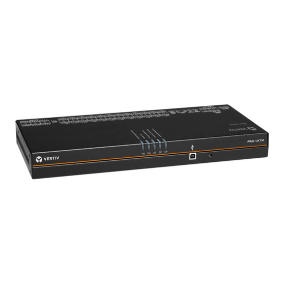
Summary of Contents for Vertiv Alber Universal Xplorer Industrial Battery Monitor
- Page 1 Alber Universal Xplorer Industrial and Telecom Monitors (UXIM) and (UXTM) Battery Monitor Calibration Guide Vertiv Corporation 1050 Daerborn Drive Columbus, OH 43085 Tel: (954) 377-7101 Fax: (954) 377-7042 www.vertivco.com 590-2106-501A/SL-249421/4200-099...
- Page 2 Notice to Users Vertiv Corporation reserves the right to make changes to this document without notice to any user or reseller of this product. Vertiv Corporation also reserves the right to substitute or terminate distribution of this document, with no obligation to notify any person or party of such substitutions or terminations.
- Page 3 Vertiv Customer Service Vertiv Customer Service is available Monday to Friday, 8:00AM to 4:30PM Eastern Time. Telephone: (954) 377-7101 Fax: (954) 377-7042 Email: alber-service@vertivco.com Website: www.vertivco.com Corporate Office Address: Vertiv Corporation 1050 Dearborn Drive Columbus, OH 43085 590-2106-501A/SL-29421/4200-099...
-
Page 4: Table Of Contents
Table of Contents Safety Information ......................... 1 General ........................... 1 Document Symbols ......................1 Safety Symbols ....................... 2 Product Safety Practices ....................2 String Current Calibration ..................... 4 Equipment Required ....................... 4 Calibration Procedure ..................... 6 590-2106-501A/SL-29421/4200-099... - Page 5 List of Figures Figure 1 - UXIM Equipment Setup ....................4 Figure 2 - UXTM Equipment Setup ..................... 5 Figure 3 - Tools Gain Calibration ....................6 List of Tables Table 1 - Calibration Input Voltages .................... 7 Table 2 - Calibration Voltages and Typical Raw Count Values ........... 7 590-2106-501A/SL-29421/4200-099...
-
Page 6: Safety Information
Never exceed equipment voltage, power ratings or capabilities. Document Symbols The symbols below appear in this manual or are affixed to the Vertiv device. It is important to review these symbols and to understand the type of instructional information they convey. -
Page 7: Safety Symbols
Equipment Service Proper installation and testing are essential to the correct functioning of the system. If you have questions, contact Vertiv and request monitor assistance. Except as explained in this manual, do not attempt to service Vertiv equipment. Any adjustment, maintenance or repair of this product must be performed by qualified personnel. - Page 8 Do not substitute parts or modify equipment. Due to the possibility of introducing additional hazards, do not substitute parts or perform any unauthorized modification to the product. If necessary, contact Vertiv to ensure the safety features are maintained. Insulation Rating For Wires Use only wire supplied with the installation kit.
-
Page 9: String Current Calibration
String Current Calibration 2. String Current Calibration Equipment Required for the UXIM • 6.5 digit voltmeter (DVM) capable of measuring 10uV - Keithley 2701 or equivalent • Precision 10uV to 500mV DC Voltage Standard (Calibration Source) – EDC MV106 or equivalent •... -
Page 10: Figure 2 - Uxtm Equipment Setup
String Current Calibration Equipment Required for the UXTM • 6.5 digit voltmeter (DVM) capable of measuring 10uV - Keithley 2701 or equivalent • Precision 10uV to 500mV DC Voltage Standard (Calibration Source) – EDC MV106 or equivalent • 18V, 10W DC power supply Figure 2 - UXTM Equipment Setup 590-2106-501A/SL-29421/4200-099... -
Page 11: Calibration Procedure
String Current Calibration Calibration Procedure Set up the equipment as shown in figure 1. The positive (+) output of the Calibration source is connected to Input 1 (-) and the negative (-) output is connected to Input 2 (+) of the UXIM/UXTM through 10K Ohm precision resistors. -
Page 12: Table 1 - Calibration Input Voltages
String Current Calibration Gain Level Input voltage 1 Input voltage 2 Gain 10B 100.100 mV 100 uV Gain 100B 10.020 mV 20 uV Gain 1000 1.020 mV 20 uV Table 1 - Calibration Input Voltages 5. Record the actual input value indicated by the DVM in the IC 1 input 1 box of the Gain Calibration tab.


Need help?
Do you have a question about the Alber Universal Xplorer Industrial Battery Monitor and is the answer not in the manual?
Questions and answers