
Subscribe to Our Youtube Channel
Related Manuals for Belden Hirschmann BAT867-R


Summary of Contents for Belden Hirschmann BAT867-R
- Page 1 User Manual Installation Industrial Access-Point / Client / Access-Bridge BAT867-R Installation BAT867-R Technical support Release 10 09/2021 https://hirschmann-support.belden.com...
- Page 2 The naming of copyrighted trademarks in this manual, even when not specially indicated, should not be taken to mean that these names may be considered as free in the sense of the trademark and tradename protection law and hence that they may be freely used by anyone. ©...
-
Page 3: Table Of Contents
Contents Important information Safety instructions About this manual Description General description Device name and product code Device view Power supply 10/100/1000 Mbit/s twisted pair port 1.5.1 Pin assignments Connections for antennas Display elements 1.7.1 Device state Reset button Installation Checking the package contents Installing and grounding the device 2.2.1 Installing the device onto the DIN rail 2.2.2 Grounding the device... - Page 4 Obtaining compliance for operation in the European Union and in the United Kingdom (UK) Configuring the transmit power Configuring WLAN transmission rates and number of spatial streams Maintenance and service Disassembly Removing the device Technical data 10.1 General technical data 10.2 Dimension drawings 10.3 Radio technology 10.4 Roaming...
-
Page 5: Important Information
Important information Note: Read these instructions carefully, and familiarize yourself with the device before trying to install, operate, or maintain it. The following notes may appear throughout this documentation or on the device. These notes warn of potential hazards or call attention to information that clarifies or simplifies a procedure. - Page 6 NOTICE NOTE provides information about procedures that do not involve the risk of injury. Installation BAT867-R Release 10 09/2021...
-
Page 7: Safety Instructions
Safety instructions WARNING UNCONTROLLED MACHINE ACTIONS To avoid uncontrolled machine actions caused by data loss, configure all the data transmission devices individually. Before you start any machine which is controlled via data transmission, be sure to complete the configuration of all data transmission devices. Failure to follow this instruction can result in death, serious injury, or equipment damage. - Page 8 Indoor operator access area: The location is accessible without tools. The person responsible for the area has provided access for the operator intentionally. The operator knows of the access possibilities, regardless of whether they need a tool. ...
- Page 9 Qualified personnel are familiar with appropriate measures against these hazards in order to reduce the risk for themselves and others. Qualified personnel receive training on a regular basis. National and international safety regulations Verify that the electrical installation meets local or nationally applicable safety regulations.
- Page 10 Requirements for connecting electrical wires Before connecting the electrical wires, always verify that the requirements listed are complied with. The following requirements apply without restrictions: The electrical wires are voltage-free. The cables used are permitted for the temperature range of the application case. ...
- Page 11 Requirements for connecting the supply voltage The following requirements apply without restrictions: All of the following requirements are complied with: The supply voltage corresponds to the voltage specified on the type plate of the device. The power supply conforms to overvoltage category I or II. ...
- Page 12 Lightning protection and surge protection The lightning protection measures must be carried out by a lightning protection professional in accordance with valid standards (such as IEC 62305 / DIN EN 62305 (VDE 0185-305)), and in accordance with the lightning protection procedures recognized and proven for the application and the environment.
- Page 13 The product can be used in residential areas (residential, commercial and light-industrial environments) and in industrial areas. Interference immunity: EN 61000-6-2 Emitted interference: EN 55032 Safety: EN 62368-1 You find more information on technical standards here: “Underlying technical standards” on page 55 Note: The assembly guidelines provided in these instructions must be strictly adhered to in order to observe the EMC threshold values.
- Page 14 Notes for Germany (DE) and Ireland (IE): DE IE Operation in the 5.8 GHz band at a radiated power (EIRP) >25 mW is subject to meeting the following conditions: Germany (DE) Frequency range: 5725 MHz to 5875 MHz Condition: The usage of this band is restricted to commercial public telecommunication services.
- Page 15 S.I. 2017 No. 1206 Radio Equipment Regulations The UKCA conformity declaration will be available to the relevant authorities at the following address: Belden UK Ltd. 1 The Technology Centre, Station Road Framlingham, IP13 9EZ, United Kingdom You find the UKCA conformity declaration as PDF file for downloading on the Internet at: https://www.doc.hirschmann.com/certificates.html...
- Page 16 Notes for the United Kingdom (UK): The Radio Equipment Regulations compliance requires compliant operation of the device in the 5 GHz band channels. Compliant operation of the device is achieved by an unchangeable determination of the country setting. To obtain the Radio Equipment Regulations compliance, perform the work steps described in chapter “Obtaining compliance for operation in the European Union and in the United...
- Page 17 Supplier's Declaration of Conformity 47 CFR § 2.1077 Compliance Information BAT867-R U.S. Contact Information Belden – St. Louis 1 N. Brentwood Blvd. 15th Floor St. Louis, Missouri 63105, United States Phone: 314.854.8000 This device complies with part 15 of the FCC rules.
- Page 18 Note for the use in the USA and in Canada The following section applies to BAT867-R variants with the characteristic value US (USA/Canada) for country approvals which are labeled as follows: Contains Transmitter Module FCC ID: TK4WLE600VX IC: 7849A-WLE600VX This equipment complies with FCC and IC RSS-102 radiation exposure limits set forth for an uncontrolled environment.
- Page 19 The FCC approval is valid only in conjunction with the listed antennas. If other antennas are used, the approval expires. The responsibility lies with the operator of the system. The required antenna impedance is 50 Ω. Recycling note After usage, this device must be disposed of properly as electronic waste, in accordance with the current disposal regulations of your county, state, and country.
-
Page 20: About This Manual
About this manual The “Installation” user manual contains a device description, safety instructions, a description of the display, and the other information that you need to install the device. Documentation mentioned in the “User Manual Installation” that is not supplied with your device as a printout can be found as PDF files for downloading on the Internet at: https://www.doc.hirschmann.com Installation BAT867-R... -
Page 21: Key
The symbols used in this manual have the following meanings: Listing Work step Subheading Installation BAT867-R Release 10 09/2021... -
Page 22: Description
Description General description The devices allow you to set up WLANs (Wireless Local Area Networks) in a local network. In contrast to a conventional network connection through copper cables and fiber optic cables, some of the communication is performed by means of a radio link. The devices allow you to install a new LAN or expand an existing LAN. -
Page 23: Device Name And Product Code
1 ... 8 Product BAT867-R IP40 housing 9 ... 10 Country approvals You can determine the current country approvals using the configurator (https:// catalog.belden.com) Example: Example: Singapore Slot 1 WLAN module Slot 2 Not assembled Slot 3 Not assembled... -
Page 24: Device View
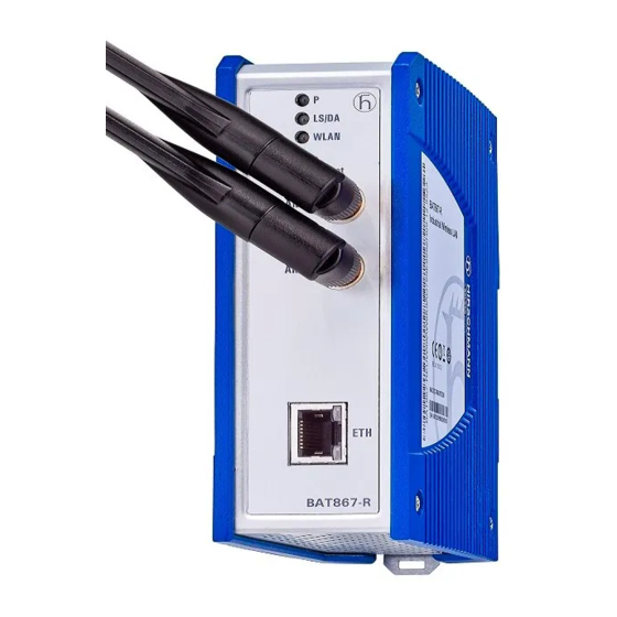
Device view Functional earth screw 2-pin terminal block for the supply voltage LED display elements Reset button Antenna connection 1 Antenna connection 2 RJ45 socket for 10/100/1000 Mbit/s Twisted Pair connections Installation BAT867-R Release 10 09/2021... -
Page 25: Power Supply
Power supply Power supply via a 2-pin terminal block A 2-pin terminal block is available to supply the device with power. Further information: See “Connecting the terminal blocks” on page 31. 10/100/1000 Mbit/s twisted pair port This port is an RJ45 socket. The 10/100/1000 Mbit/s twisted pair port allows you to connect network components according to the IEEE 802.3 10BASE-T/100BASE-TX/ 1000BASE-T standard. -
Page 26: Pin Assignments
1.5.1 Pin assignments RJ45 10/100 Mbit/s 1000 Mbit/s MDI mode BI_DA+ TX− BI_DA− BI_DB+ — BI_DC+ — BI_DC− RX− BI_DB− — BI_DD+ — BI_DD− MDI-X mode BI_DB+ RX− BI_DB− BI_DA+ — BI_DD+ — BI_DD− TX− BI_DA− — BI_DC+ — BI_DC− Installation BAT867-R Release 10 09/2021... -
Page 27: Connections For Antennas
Connections for antennas For the operation of the device you need antennas. The devices have 2 Reverse SMA connectors for connecting external antennas. The "Antenna Guide" document provides an overview of the antennas that can be used as well as the suitable antenna accessories. The manual is available for download on the Internet: https:// www.doc.hirschmann.com... -
Page 28: Reset Button
WLAN Activity Meaning Color green inverse flashing Number of flashes corresponds to number of connected WLAN stations and P2P radio lines. green flashing DFS scanning or another scan procedure Display of signal strength in client or P2P flashing Device has detected at least one hardware error. -
Page 29: Installation
Installation The devices have been developed for practical application in a harsh industrial environment. On delivery, the device is ready for operation. Perform the following steps to install and configure the device: Checking the package contents Installing and grounding the device ... -
Page 30: Grounding The Device
To mount the device onto a horizontally mounted 35 mm DIN rail according to DIN EN 60715, proceed as follows: Slide the upper snap-in guide of the device into the DIN rail. Pull the rail lock slide down using a screwdriver, and press the lower part of the device against the DIN rail. -
Page 31: Installing The Antennas
Installing the antennas The devices have 2 Reverse SMA connectors for connecting external antennas. Note: When using 2 antennas type BAT-ANT-RSMA-2AGN-R, you must align each antenna in another spatial direction (x-y) so that both antennas are arranged at right angles to each other. When mounting only 1 antenna, insert a terminating resistor into the unused socket. -
Page 32: Operating The Device
Figure 1: Supply voltage with characteristic value U: 2-pin terminal block with screw lock Type of the voltages Specification of the supply Pin assignment on the device that can be voltage connected DC voltage Rated voltage − Minus terminal of the supply 24 V DC voltage Voltage range incl. -
Page 33: Connecting Data Cables
Relevant for North America for power supply via a 2-pin terminal block: The torque for tightening the supply voltage terminal block on the device is 0.51 Nm (4.5 lb-in). Mount the terminal block on the device using screws. By connecting the supply voltage via the terminal block, you start the operation of the device. -
Page 34: Making Basic Settings
Making basic settings The IP parameters must be entered when the device is installed for the first time. The device provides the following options for configuring IP addresses: Entry via the HiDiscovery protocol in the applications HiDiscovery or Industrial HiVision ... -
Page 35: First Login (Password Change)
Type in your new password. Choose a password that contains at least 8 characters which includes upper-case characters, lower-case characters, numerical digits and special characters. Confirm your new password. For further information see: https://hirschmann-support.belden.com/en/kb/required-password-change- new-procedure-for-first-time-login Installation BAT867-R Release 10 09/2021... -
Page 36: Obtaining Compliance For Operation In The European Union And In The United Kingdom (Uk)
Obtaining compliance for operation in the European Union and in the United Kingdom (UK) For operation in the European Union, the device must comply with the Radio Equipment Directive (RED) 2014/53/EU. For operation in the United Kingdom (UK), the device must comply with the Radio Equipment Regulations. - Page 37 Note: To check the country setting and correct it, type no. Then check the country setting with the following command: ls Setup/WLAN/ Country. To obtain RED compliance or Radio Equipment Regulations compliance, type yes. This makes the country setting unchangeable. Subsequently, the device restarts.
- Page 38 Note: The country setting “Europe” is valid for all European countries and the United Kingdom (UK). Specific country settings such as “France” or “Germany” include additional country specific channels in comparison to the “Europe” country setting. The device ignores specific country settings and uses the country setting “Europe”...
-
Page 39: Configuring The Transmit Power
Configuring the transmit power Note: The operator of a WLAN radio installation must adhere to the applicable transmission threshold values. Use the graphical user interface WEBconfig or the LANconfig software. You can download the LANconfig software from the Hirschmann product pages (www.hirschmann.com). - Page 40 Subtract from the antenna gain the attenuation by cables and by surge protection devices. Enter the calculated value in the “Antenna gain” field. To save the value, click the “Send” button. Installation BAT867-R Release 10 09/2021...
-
Page 41: Configuring Wlan Transmission Rates And Number Of Spatial Streams
Configuring WLAN transmission rates and number of spatial streams Note: In most of the cases it is not necessary to change the default values. If your use case requires adjustments, let a WLAN expert make the adjustments. Use the graphical user interface WEBconfig or the LANconfig software. You can download the LANconfig software from the Hirschmann product pages (www.hirschmann.com). -
Page 42: Maintenance And Service
Maintenance and service When designing this device, Hirschmann largely avoided using high-wear parts. The parts subject to wear and tear are dimensioned to last longer than the lifetime of the product when it is operated normally. Operate this device according to the specifications. ... -
Page 43: Disassembly
Disassembly Removing the device Disconnect the data cables. Disable the supply voltage. Remove the terminal connector from the device. Remove the antennas. Disconnect the grounding. Insert a screwdriver horizontally below the housing into the locking gate. ... -
Page 44: 10 Technical Data
10 Technical data 10.1 General technical data Dimensions BAT867-R See “Dimension drawings” on page 45. W × H × D Weight 520 g (18.3 oz) Supply voltage Rated voltage 24 V DC Voltage range incl. maximum 18 V DC ... 32 V DC tolerances Connection type 2-pin terminal block... -
Page 45: Dimension Drawings
10.2 Dimension drawings inch 1.22 49,4 1.94 118,2 4.65 113,1 4.45 117,3 4.62 122,5 4.82 Installation BAT867-R Release 10 09/2021... -
Page 46: Radio Technology
10.3 Radio technology Antenna connection 2 × Reverse SMA connector Range Depending on the antenna used, frequency range and data rate Encryption IEEE 802.11i/WPA2 with passphrase or IEEE 802.1x and hardware-accelerated AES Closed Network WEP 64 WEP 128 ... -
Page 47: Receiving Sensitivity, Transmit Power And Data Rate
10.5 Receiving sensitivity, transmit power and data rate The values of the WLAN module shown in the following tables are subject to a tolerance of ±2 dB. If you use only 1 antenna, the transmit power is reduced by 3 dB. The values are in no case to be perceived as a guaranteed property of the overall product. -
Page 48: Ieee 802.11A
10.5.3 IEEE 802.11a IEEE 802.11a Frequency range 5.180 GHz to 5.825 GHz Bandwidth 20 MHz Data rate Transmit power Receiving sensitivity 6 Mbit/s 23 dBm −94 dBm 9 Mbit/s 23 dBm −94 dBm 12 Mbit/s 23 dBm −92 dBm 18 Mbit/s 23 dBm −90 dBm 24 Mbit/s... - Page 49 IEEE 802.11n Frequency range 2.412 GHz to 2.472 GHz Bandwidth 40 MHz Coding Transmit power Receiving sensitivity MCS 2 / 10 23 dBm −85 dBm MCS 3 / 11 22 dBm −82 dBm MCS 4 / 12 22 dBm −79 dBm MCS 5 / 13 22 dBm −75 dBm...
-
Page 50: Ieee 802.11Ac
IEEE 802.11n Frequency range 5.180 GHz to 5.825 GHz Bandwidth 40 MHz Coding Transmit power Receiving sensitivity MCS 5 / 13 19 dBm −75 dBm MCS 6 / 14 18 dBm −73 dBm MCS 7 / 15 17 dBm −73 dBm Table 11: IEEE 802.11n, frequency range 5.180 GHz to 5.825 GHz, bandwidth 40 MHz 10.5.5... -
Page 51: Emc And Immunity
IEEE 802.11ac Frequency range 5.180 GHz to 5.825 GHz Bandwidth 40 MHz Coding Transmit power Receiving sensitivity MCS 5 19 dBm −75 dBm MCS 6 18 dBm −73 dBm MCS 7 17 dBm −73 dBm MCS 8 16 dBm −69 dBm MCS 9 16 dBm −66 dBm... -
Page 52: Network Range
EMC interference immunity EN 61000-4-3 Electromagnetic field 80 MHz ... 1000 MHz 10 V/m 1400 MHz ... 2700 MHz 10 V/m EN 61000-4-4 Fast transients (burst) DC power line ±2 kV Data line ±4 kV EN 61000-4-5 Voltage surges DC power line ±1 kV line/ground;... -
Page 53: Scope Of Delivery, Order Numbers And Accessories
11 Scope of delivery, order numbers and accessories Scope of delivery Amount Article 1 × Device 1 × Safety and general information sheet 1 × Sheet with the conformity declarations for the European Union and the United Kingdom (UK) 1 ×... - Page 54 Accessories Note that products recommended as accessories may have different characteristics to those of the device, which may limit the application range of the overall system. For example, if you add an accessory with IP20 to a device with IP65, the degree of protection of the overall system is reduced to IP20.
-
Page 55: 12 Underlying Technical Standards
12 Underlying technical standards Name CAN/CSA 22.2 No. 62368-1 Information Technology Equipment – Safety – Part 1: General Requirements EN 50121-4 Railway applications – EMC – Emission and immunity of the signaling and telecommunications apparatus (Rail Trackside) EN 55032 Electromagnetic compatibility of multimedia equipment – Emission Requirements EN 60529 Degrees of protection provided by housing –... -
Page 56: A Further Support
You find the addresses of our partners on the Internet at http://www.hirschmann.com. A list of local telephone numbers and email addresses for technical support directly from Hirschmann is available at https://hirschmann-support.belden.com. This site also includes a free of charge knowledge base and a software download section. Customer Innovation Center... - Page 57 Installation BAT867-R Release 10 09/2021...
Need help?
Do you have a question about the Hirschmann BAT867-R and is the answer not in the manual?
Questions and answers