
Subscribe to Our Youtube Channel
Related Manuals for Belden Hirschmann OpenBAT BAT-R


Summary of Contents for Belden Hirschmann OpenBAT BAT-R
- Page 1 User Manual Installation Open Dual-Band Industrial Access-Point / Client / Access- Bridge OpenBAT-Family: BAT-R Installation BAT-R Technical support Release 17 12/2020 https://hirschmann-support.belden.com...
- Page 2 The naming of copyrighted trademarks in this manual, even when not specially indicated, should not be taken to mean that these names may be considered as free in the sense of the trademark and tradename protection law and hence that they may be freely used by anyone. ©...
-
Page 3: Table Of Contents
Contents Important information Safety instructions About this manual Description General description Device name and product code Device view Power supply 1.4.1 Supply voltage with the characteristic value C (24 V DC ... 48 V DC) 1.4.2 Supply voltage with the characteristic value K (60 V DC ... - Page 4 Installation Checking the package contents Installing and grounding the device 2.2.1 Installing the device onto the DIN rail 2.2.2 Mounting on a vertical flat surface 2.2.3 Grounding the device Installing an SFP transceiver (optional) Installing the antennas Connecting the terminal blocks (optional) 2.5.1 Supply voltage with the characteristic value C (24 V DC ...
- Page 5 Disassembly Removing the device Removing an SFP transceiver (optional) Technical data 10.1 General technical data 10.2 Dimension drawings 10.3 Radio technology 10.4 Roaming 10.5 Receiving sensitivity, transmit power, and data rate of the WLAN module version EWLAN1 (Approvals 2, characteristic value M, V or 9) 10.5.1 IEEE 802.11b 10.5.2 IEEE 802.11g...
-
Page 6: Important Information
Important information Note: Read these instructions carefully, and familiarize yourself with the device before trying to install, operate, or maintain it. The following notes may appear throughout this documentation or on the device. These notes warn of potential hazards or call attention to information that clarifies or simplifies a procedure. - Page 7 NOTICE NOTE provides information about procedures that do not involve the risk of injury. Installation BAT-R Release 17 12/2020...
-
Page 8: Safety Instructions
Safety instructions WARNING UNCONTROLLED MACHINE ACTIONS To avoid uncontrolled machine actions caused by data loss, configure all the data transmission devices individually. Before you start any machine which is controlled via data transmission, be sure to complete the configuration of all data transmission devices. Failure to follow this instruction can result in death, serious injury, or equipment damage. - Page 9 Indoor operator access area: The location is accessible without tools. The person responsible for the area has provided access for the operator intentionally. The operator knows of the access possibilities, regardless of whether they need a tool. ...
- Page 10 Device casing Only technicians authorized by the manufacturer are permitted to open the casing. Never insert pointed objects (narrow screwdrivers, wires, etc.) into the device or into the connection terminals for electric conductors. Do not touch the connection terminals. ...
- Page 11 Lightning protection and surge protection Applies exclusively to antennas installed outdoors: The lightning protection measures must be carried out by a lightning protection professional in accordance with valid standards (such as IEC 62305 / DIN EN 62305 (VDE 0185-305)), and in accordance with the lightning protection procedures recognized and proven for the application and the environment.
- Page 12 Requirements for connecting the supply voltage The following requirements apply without restrictions: All variants All of the following requirements are complied with: The supply voltage corresponds to the voltage specified on the type plate of the device. The power supply conforms to overvoltage category I or II.
- Page 13 Enable the supply voltage for the device only when the following requirements are fulfilled: the housing is closed the terminal blocks are wired correctly the terminal blocks for the power supply are connected For supply voltage connections with protective conductor connection: First connect the protective conductor before connecting the wires for the supply voltage.
- Page 14 E marking The labeled devices comply with the regulations contained in the following European directive(s): Regulation No. 10 of the Economic Commission for Europe of the United Nations (UN/ECE): Devices with an approval are labeled with the E type approval mark. The optical transceivers M-SFP-SX/LC-EEC and M-SFP-LX/LC-EEC can be used (relevant for devices with approval characteristic value M).
- Page 15 Notes for countries with the following country codes: AT BE BG CH CY CZ DE DK EE EL ES HR HU LV MT NL NO PL PT RO RS SE TR UK The RED compliance requires compliant operation of the device in the 5 GHz band channels.
- Page 16 Applies to the operation of the BAT-ANT-N-14G-IP23 antenna: In addition to the antenna cable supplied, the use of the BAT-CLB-2 N m-f antenna is required. See “Accessories” on page 72. Applies exclusively to BAT-R device variants featuring Approvals 2 with characteristic value V (SRD): The maximum radiated power (EIRP) is 25 mW according to EN 300 440 (Short Range Device).
- Page 17 Notes for Germany (DE), Ireland (IE), and the United Kingdom (UK): DE IE Operation in the 5.8 GHz band at a radiated power (EIRP) >25 mW is subject to meeting the following conditions: Germany (DE) Frequency range: 5725 MHz to 5875 MHz Condition: The usage of this band is restricted to commercial public telecommunication services.
- Page 18 Supplier's Declaration of Conformity 47 CFR § 2.1077 Compliance Information BAT-R U.S. Contact Information Belden – St. Louis 1 N. Brentwood Blvd. 15th Floor St. Louis, Missouri 63105, United States Phone: 314.854.8000 This device complies with part 15 of the FCC rules.
- Page 19 FCC ID: U99EWLAN1 IC: 4019A-EWLAN1 This equipment complies with FCC and IC RSS-102 radiation exposure limits set forth for an uncontrolled environment. Install and operate this equipment with a minimum distance of 19.7 in (50 cm) (related to a 9 dBi antenna) between the radiation source and your body.
- Page 20 Applies exclusively to device variants with approval for the 4.9 GHz band (Approvals 2, characteristic value P) according to FCC 47CFR Part 90 Subpart Y: Operation of the device in the 4.9 GHz band requires trained personnel familiar with the regulatory requirements for operation according to FCC 47CFR Part 90 Subpart Y.
- Page 21 Note for the use in Oman This note applies to BAT-R variants with the characteristic value OM (Oman) for country approvals: This telecommunication equipment complies with the technical requirements of the Telecommunications Regulatory Authority (TRA) and is labeled as follows: OMAN - TRA R/4116/17 D100428...
-
Page 22: About This Manual
About this manual The “Installation” user manual contains a device description, safety instructions, a description of the display, and the other information that you need to install the device. Documentation mentioned in the “User Manual Installation” that is not supplied with your device as a printout can be found as PDF files for downloading on the Internet at: https://www.doc.hirschmann.com Installation BAT-R... -
Page 23: Key
The symbols used in this manual have the following meanings: Listing Work step Subheading Installation BAT-R Release 17 12/2020... -
Page 24: Description
Description General description The devices allow you to set up WLANs (Wireless Local Area Networks) in a local network. In contrast to a conventional network connection through copper cables and fiber optic cables, some of the communication is performed by means of a radio link. The devices allow you to install a new LAN or expand an existing LAN. -
Page 25: Device Name And Product Code
The characteristic values stand for specific product properties. You have numerous options of combining the device characteristics. You can determine the possible combinations using the configurator which is available in the Belden Online Catalog https://catalog.belden.com on the web page of the device. - Page 26 Devices of the OpenBAT BAT-R DIN Rail housing family 6 ... 7 Country approvals You can determine the current country approvals using the configurator (https:// catalog.belden.com) Example: Example: Singapore Slot 1 WLAN module Slot 2 WLAN module Not assembled Slot 3...
- Page 27 Item Characteristic Characteri Description stic value 17 ... 18 Ethernet port 1 Combo port – you can use these ports for alternative purposes: Supply voltage with characteristic value C (24 V DC ... 48 V DC) and K (60 V DC ... 250 V DC / 110 V AC ... 230 V AC, 50 Hz ...
-
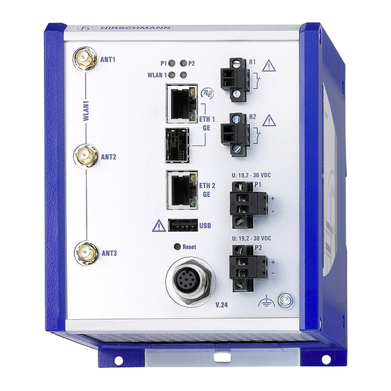
Page 28: Device View
Device view 4 4a 4b Front view: on the left: device variants featuring supply voltage with the characteristic value C or K rechts: Gerätevarianten mit Versorgungsspannung Merkmalswert W not shown: supply voltage with the characteristic value W and temperature range with the characteristic value K WLAN module 1: 3 ×... -
Page 29: Power Supply
Device variants featuring supply voltage with characteristic value C (24 V DC ... 48 V DC) or K (60 V DC ... 250 V DC / 110 V AC ... 230 V AC, 50 Hz ... 60 Hz) Supply voltage connection 1 ... -
Page 30: Supply Voltage With The Characteristic Value C
1.4.1 Supply voltage with the characteristic value C (24 V DC ... 48 V DC) A 2-pin terminal block is available to supply the device with power. Further information: “Supply voltage with the characteristic value C (24 V DC ... 48 V DC)” on page 41 1.4.2 Supply voltage with the characteristic value K... -
Page 31: Gigabit Combo Port
1.5.1 Gigabit combo port You have the option of alternatively connecting a twisted pair cable via a RJ45 socket or an optical fiber via a SFP transceiver to a combo port. Only plug a connector or SFP transceiver that you want to use for the data transmission into the socket of the combo port. -
Page 32: 10/100/1000 Mbit/S Twisted-Pair Connection (Optional)
1000 Mbit/s F/O port The 1000 Mbit/s F/O port offers you the ability to connect network components according to the IEEE 802.3 1000BASE-SX/1000BASE-LX standard. This port supports: Full duplex mode 1.5.2 10/100/1000 Mbit/s twisted-pair connection (optional) See the properties of this port “10/100/1000 Mbit/s twisted pair port”... -
Page 33: Connections For Antennas
Connections for antennas For the operation of the device you need antennas. The devices have 3 reverse SMA connections (SMA = Sub-Miniature Version A) on each WLAN module. The "Antenna Guide" document provides an overview of the antennas that can be used as well as the suitable antenna accessories. The manual is available for download on the Internet: https:// www.doc.hirschmann.com... -
Page 34: Port Status
LED display elements for device status WLAN2 For device variants with 2 WLAN modules: WLAN module 2 Note: For device variants with 1 WLAN module, this LED is unlabeled and solely lights up after the configuration is reset (hard reset). See “Reset button”... -
Page 35: Management Interfaces 1.8.1 V.24 Interface (External Management)
Management interfaces 1.8.1 V.24 interface (external management) This interface is designed as an 8-pin, “A”-coded M12 plug. The V.24 user interface is serial and allows you to connect the following devices directly: External management station (VT100 terminal or PC with appropriate terminal emulation). -
Page 36: Usb Interface
Pins of the M12 socket on Pin assignment for the connection Pins of the DB9 plug on the device with a cable the external device Table 5: Pin assignment for the connection with a cable: 8-pin, „A“-coded M12 plug to DB9 connector You can order a terminal cable M12, 8-pin, to DB9 as an accessory. -
Page 37: Signal Contact
Connectors: type A Supplies current of max. 500 mA Voltage not potential-separated Figure Function VCC (VBus) - Data + Data Ground (GND) Table 7: Pin assignment of the USB interface Signal contact Figure 1: Signal contact: 2-pin terminal block with screw locking You have the option of setting the signal contact manually using the device management. -
Page 38: Installation
Installation The devices have been developed for practical application in a harsh industrial environment. On delivery, the device is ready for operation. Perform the following steps to install the device: Checking the package contents Installing and grounding the device ... -
Page 39: Installing The Device Onto The Din Rail
2.2.1 Installing the device onto the DIN rail To mount the device onto a horizontally mounted 35 mm DIN rail according to DIN EN 60715, proceed as follows: Slide the upper snap-in guide of the device into the DIN rail. ... -
Page 40: Installing An Sfp Transceiver (Optional)
Installing an SFP transceiver (optional) Use only Hirschmann SFP transceivers which are suitable for usage with the device. See “Accessories” on page 72. Proceed as follows: Remove the protection cap from the SFP transceiver. Push the transceiver with the lock closed into the slot until it latches in. Installing the antennas 1 WLAN module 1: Antenna connection 1... -
Page 41: Connecting The Terminal Blocks (Optional)
Connecting the terminal blocks (optional) WARNING ELECTRIC SHOCK Before connecting the electrical wires, always verify that the requirements listed are complied with. See “Requirements for connecting electrical wires” on page 11. See “Requirements for connecting the supply voltage” on page 12. Never insert sharp objects (small screwdrivers, wires, etc.) into the connection terminals for electric conductors, and do not touch the terminals. -
Page 42: Supply Voltage With The Characteristic Value K
Perform the following steps for the supply voltage to be connected, or for device variants with 2 supply voltage connections of this type, for every supply voltage to be connected. Remove the terminal connector from the device. Connect the wires according to the pin assignment on the device with the clamps. -
Page 43: 50 Hz
Type of the voltages Specification of the supply Pin assignment on the device that can be voltage connected AC voltage Rated voltage range AC: Outer conductor 110 V AC ... 230 V AC, Neutral conductor 50 Hz ... 60 Hz Protective conductor Voltage range AC incl. -
Page 44: Signal Contact
For every supply voltage to be connected, perform the following steps: Remove the terminal connector from the device. Connect the wires according to the pin assignment on the device with the clamps. Fasten the wires in the terminal block by tightening the terminal screws. 2.5.4 Signal contact For every signal contact to be connected, make sure the following... -
Page 45: Connecting The Power Supply Through Poe
Use screws to secure the connectors to the device. Enable the supply voltage. 2.6.2 Connecting the power supply through PoE Note: For devices with 2 WLAN modules, the option of suppling power via PoE is unavailable. NOTICE MATERIAL DAMAGE In a PoE installation, use only devices that comply with the IEEE 802.3af/at standard. -
Page 46: Gigabit Combo Port
2.7.1 Gigabit combo port 10/100/1000 Mbit/s PoE PD port Further information: “10/100/1000 Mbit/s PoE PD port” on page 31 Connect the data cables according to your requirements. 1000 Mbit/s F/O port Further information: “1000 Mbit/s F/O port” on page 32 Make sure that you connect LH ports exclusively with LH ports, SX ports exclusively with SX ports, and LX ports exclusively with LX ports. -
Page 47: Making Basic Settings
Making basic settings The IP parameters must be entered when the device is installed for the first time. The device provides the following options for configuring IP addresses: Input via the V.24 interface Entry via the HiDiscovery protocol in the applications HiDiscovery or Industrial HiVision ... -
Page 48: First Login (Password Change)
Type in your new password. Choose a password that contains at least 8 characters which includes upper-case characters, lower-case characters, numerical digits and special characters. Confirm your new password. For further information see: https://hirschmann-support.belden.com/en/kb/required-password-change- new-procedure-for-first-time-login Installation BAT-R Release 17 12/2020... -
Page 49: Obtaining Compliance For Operation In The European Union
Obtaining compliance for operation in the European Union For operation in the European Union, the device must comply with the Radio Equipment Directive (RED) 2014/53/EU. The RED compliance requires compliant operation of the device in the 5 GHz band channels. Compliant operation of the device is achieved by an unchangeable determination of the country setting. - Page 50 Note: To check the country setting and correct it, type no. Then check the country setting with the following command: ls Setup/WLAN/ Country. To obtain RED compliance, type yes. This makes the country setting unchangeable. Subsequently, the device restarts. Graphical user interface ...
- Page 51 To confirm your choice, click the “OK” button. In the LANconfig device overview, highlight the row containing the desired device. In the menu bar, select Device > RED compliance. Note: To check the country setting and correct it, click the “No” button. Then open the Configuration >...
-
Page 52: Configuring The Transmit Power
Configuring the transmit power Note: This chapter does NOT apply to device variants with approval for the 4.9 GHz band (Approvals 2, characteristic value P). For device variants with approval for the 4.9 GHz band see “Configuring the transmit power for the 4.9 GHz band”... - Page 53 Subtract from the antenna gain the attenuation by cables and by surge protection devices. Enter the calculated value in the “Antenna gain” field. To save the value, click the “Send” button. Installation BAT-R Release 17 12/2020...
-
Page 54: Configuring The Transmit Power For The 4.9 Ghz Band
Configuring the transmit power for the 4.9 GHz band Note: This chapter exclusively applies to device variants with approval for the 4.9 GHz band (Approvals 2, characteristic value P). Note: The operator of a WLAN radio installation must adhere to the applicable transmission threshold values. - Page 55 To save the value, click the “Send” button. Installation BAT-R Release 17 12/2020...
-
Page 56: Maintenance And Service
Maintenance and service When designing this device, Hirschmann largely avoided using high-wear parts. The parts subject to wear and tear are dimensioned to last longer than the lifetime of the product when it is operated normally. Operate this device according to the specifications. ... -
Page 57: Disassembly
Disassembly Removing the device Disconnect the data cables. Disable the supply voltage. Disconnect the terminal blocks. Remove the antennas. Disconnect the grounding. Insert a screwdriver horizontally below the housing into the locking gate. Pull the locking gate down without tilting the screwdriver. ... -
Page 58: 10 Technical Data
10 Technical data 10.1 General technical data Weight Device variants featuring supply voltage with approx. 52.91 oz characteristic value C (24 V DC ... 48 V DC) or K (1500 g) (60 V DC ... 250 V DC / 110 V AC ... 230 V AC, 50 Hz ... - Page 59 Supply voltage Class 2 with the Rated voltage DC: 24 V DC characteristic Voltage range DC incl. 16.8 V DC ... 32 V DC value W maximum tolerances: Connection type 2-pin terminal block Power loss buffer >10 ms at 20.4 V DC Overload current protection on Non-replaceable fuse the device...
-
Page 60: Dimension Drawings
Signal contact Switching current max. 1 A SELV according to IEC 60950-1 “FAULT” or ES1 according to IEC/EN 62368-1 Switching voltage Supply voltage with characteristic value C (24 V DC ... 48 V DC) and K (60 V DC ... 250 V DC / 110 V AC ... - Page 61 150,6 mm 120,8 mm 5.93 in 4.76 in Figure 6: Dimensions of device variants featuring supply voltage with characteristic value C (24 V DC ... 48 V DC) or K (60 V DC ... 250 V DC / 110 V AC ... 230 V AC, 50 Hz ...
-
Page 62: Radio Technology
10.3 Radio technology Antenna connection For each WLAN module: 3 × reverse SMA connection Range Depending on the antenna used, frequency range and data rate Encryption IEEE 802.11i/WPA2 with passphrase or IEEE 802.1x and hardware-accelerated AES Closed Network ... -
Page 63: Receiving Sensitivity, Transmit Power, And Data Rate Of The Wlan Module Version Ewlan1 (Approvals 2, Characteristic Value M, V Or 9)
10.5 Receiving sensitivity, transmit power, and data rate of the WLAN module version EWLAN1 (Approvals 2, characteristic value M, V or 9) The values shown in the following tables are the maximum values of the WLAN module version EWLAN1. The values are in no case to be perceived as a guaranteed property of the overall product. -
Page 64: Ieee 802.11A
a. The typical transmit power was reduced as follows to be compliant with FCC regulations for all modulations: - Channels 4, 7 and 8: Reduction by 3 dB - Channels 2, 3, 5, 6 and 9: Reduction by 4 dB - Channel 10: Reduction by 5 dB - Channel 1: Reduction by 6 dB - Channel 11: Reduction by 8 dB... - Page 65 IEEE 802.11n Frequency range 2.412 GHz to 2.472 GHz (for FCC: 2.412 GHz to 2.462 GHz) Coding Typical transmit power Typical receiving sensitivity MCS 9 21 dBm -90 dBm MCS 10 22 dBm -86 dBm MCS 11 21 dBm -82 dBm MCS 12 16 dBm -79 dBm...
- Page 66 IEEE 802.11n Frequency range 5.180 GHz to 5.825 GHz (for FCC: 5.180 GHz to 5.240 GHz and 5.745 GHz to 5.825 GHz) Coding Typical transmit power Typical receiving sensitivity MCS 6 14 dBm -75 dBm MCS 7 14 dBm -73 dBm MCS 8 20 dBm -92 dBm...
-
Page 67: Receiving Sensitivity, Transmit Power, And Data Rate Of The Wlan Module Version Ewlan1 For Device Variants With Approval For The 4.9 Ghz Band (Approvals 2, Characteristic Value P)
10.6 Receiving sensitivity, transmit power, and data rate of the WLAN module version EWLAN1 for device variants with approval for the 4.9 GHz band (Approvals 2, characteristic value P) Applies exclusively to WLAN module version EWLAN1 for device variants with approval for the 4.9 GHz band (Approvals 2, characteristic value P) according to FCC 47CFR Part 90 Subpart Y. -
Page 68: Ieee 802.11A, Bandwidth 20 Mhz
IEEE 802.11a Frequency range 4.940 GHz to 4.990 GHz Bandwidth 10 MHz Data rate Typical transmit power 9 Mbit/s 14 dBm 12 Mbit/s 14 dBm 18 Mbit/s 13 dBm 24 Mbit/s 12 dBm 27 Mbit/s 11 dBm Table 18: IEEE 802.11a, Frequency range 4.940 GHz to 4.990 GHz, Bandwidth 10 MHz, Channels 19-27 10.6.3 IEEE 802.11a, Bandwidth 20 MHz... -
Page 69: Network Range
EMC interference immunity EN 61000-4-4 Fast transients (burst), test level 4 DC power line ±4 kV AC Power Line ±4 kV Data line ±4 kV EN 61000-4-5 Voltage surges DC power line ±2 kV line/ground; ±1 kV line/line AC Power Line ±4 kV line/ground;... -
Page 70: Power Consumption/Power Output
Product Wave Fiber System Example Fiber code length attenuatio for F/O attenuatio Dispersion M-SFP-... cable length -LX/LC... MM 1310 nm 50/125 µm 0 dB ... 0 mi ... 1.0 dB/km 800 MHz×km 10.5 dB 0.34 mi (0 km ... 0.55 km) -LX/LC... -
Page 71: Scope Of Delivery, Order Numbers And Accessories
11 Scope of delivery, order numbers and accessories Scope of delivery Amount Article 1 × Device 1 × Safety and general information sheet 1 × EU Declaration of Conformity 1 × Terminal cable: M12 plug, 8-pin on DB9 socket 3 ×... - Page 72 Accessories Note that products recommended as accessories may have different characteristics to those of the device, which may limit the application range of the overall system. For example, if you add an accessory with IP20 to a device with IP65, the degree of protection of the overall system is reduced to IP20.
-
Page 73: 12 Underlying Technical Standards
12 Underlying technical standards Name CAN/CSA 22.2 No. 60950-1 Information Technology Equipment – Safety – Part 1: General Requirements ECE No. 10 E type approval for use in vehicles EN 300 328 Electromagnetic compatibility and radio spectrum matters (ERM) - bandwidth transfer systems - data transmission equipment operating in 2.4 GHz ISM band and using spread spectrum modulation technology EN 300 440... - Page 74 The device has an approval based on a specific standard exclusively if the approval indicator appears on the device casing. The device generally fulfills the technical standards named in their current versions. Installation BAT-R Release 17 12/2020...
-
Page 75: A Further Support
A list of local telephone numbers and email addresses for technical support directly from Hirschmann is available at https:// hirschmann-support.belden.com. This site also includes a free of charge knowledge base and a software download section. Hirschmann Competence Center The Hirschmann Competence Center is ahead of its competitors on three counts with its complete range of innovative services: ...
Need help?
Do you have a question about the Hirschmann OpenBAT BAT-R and is the answer not in the manual?
Questions and answers