
Related Manuals for Belden Hirschmann BAT-F Series


Summary of Contents for Belden Hirschmann BAT-F Series
- Page 1 User Manual Installation Open Dual-Band Industrial Access-Point / Client / Access- Bridge OpenBAT-Family: BAT-F Installation BAT-F Technical support Release 09 08/2015 https://hirschmann-support.belden.eu.com...
- Page 2 The naming of copyrighted trademarks in this manual, even when not specially indicated, should not be taken to mean that these names may be considered as free in the sense of the trademark and tradename protection law and hence that they may be freely used by anyone. ©...
-
Page 3: Table Of Contents
Contents Safety instructions About this manual Description General description Device name and product code Device view Power supply 1.4.1 Supply voltage with the characteristic value C 1.4.2 Supply voltage with the characteristic value K 1.4.3 Supply voltage with the characteristic value P 1.4.4 Supply voltage with the characteristic value W Ethernet ports 1.5.1 Gigabit combo port... - Page 4 Connecting the power supply and signal lines 2.5.1 Supply voltage with the characteristic value C 2.5.2 Supply voltage with the characteristic value K 2.5.3 Supply voltage with the characteristic value W 2.5.4 Signal contact Operating the device 2.6.1 Connecting the power supply through a 7/8" connector 2.6.2 Connecting the power supply through PoE Connecting data cables...
-
Page 5: Safety Instructions
Safety instructions WARNING UNCONTROLLED MACHINE ACTIONS To avoid uncontrolled machine actions caused by data loss, configure all the data transmission devices individually. Before you start any machine which is controlled via data transmission, be sure to complete the configuration of all data transmission devices. Failure to follow these instructions can result in death, serious injury, or equipment damage. - Page 6 Indoor operator access area: The location is accessible without tools. The person responsible for the area has provided access for the operator intentionally. The operator knows of the access possibilities, regardless of whether they need a tool. If all the following requirements are fulfilled, you have the option of installing the device in the indoor operator access area.
- Page 7 Qualification requirements for personnel Only allow qualified personnel to work on the device. Qualified personnel have the following characteristics: Qualified personnel are properly trained. Training as well as practical knowledge and experience make up their qualifications. This is the prerequisite for grounding and labeling circuits, devices, and systems in accordance with current standards in safety technology.
- Page 8 Supply voltage The supply voltage is electrically isolated from the housing. Connect only a supply voltage that corresponds to the type plate of your device. Only for device variants featuring supply voltage with the characteristic value K: See “Device name and product code”...
- Page 9 The cables used are permitted for the temperature range of the application case. Relevant for North America: The power cords are suitable for ambient air temperatures of at least 167 °F (75 °C). The power cord wires are made of copper. Start connecting the electrical wires only if all the above safety requirements are fulfilled.
- Page 10 Relevant for use in Ex Zone 2 according to ATEX 95 (European directive 94/9/EC) In Ex zone 2, only devices with a corresponding label may be operated. When operating the BAT-F types with the characteristic value G for approvals 1 (ATEX zone 2), the following applies: ...
- Page 11 Relevant for use in explosion hazard areas (Hazardous Locations, Class I, Division 2): In Ex zone 2, only the devices with a corresponding label may be operated in explosion hazard areas Class I, Division 2. When operating the BAT-F types in explosion hazard areas Class I, Division 2, the following applies: Class I, Div.
- Page 12 E marking The labeled devices comply with the regulations contained in the following European directive(s): Rule No. 10 of the Economic Commission for Europe (ECE): Devices with an approval are labeled with the E type-approval mark. The optical transceivers M-SFP-SX/LC EEC und M-SFP-LX/LC EEC can be used (relevant for devices with certificates characteristic value M).
- Page 13 The product can be used in living areas (living area, place of business, small business) and in industrial areas. Notes: Applies to the operation of devices with antennas having a gain of more than 8 dBi: At temperatures lower than −25 °C a power reduction of 4 dB using a software setting has to be applied.
- Page 14 FCC note: This device complies with part 15 of the FCC rules. Operation is subject to the following two conditions: This device may not cause harmful interference, and This device must accept any interference received, including interference that may cause undesired operation. This equipment has been tested and found to comply with the limits for a Class B digital device, pursuant to part 15 of the FCC Rules.
- Page 15 This Class B digital apparatus complies with Canadian ICES-003. Cet appareil numérique de la classe B est conforme à la norme NMB-003 du Canada. To reduce potential radio interference to other users, the antenna type and its gain should be so chosen that the equivalent isotropically radiated power (EIRP) is not more than that permitted for successful communication.
- Page 16 This transmitter is restricted to indoor use only within the 5.15-5.25 GHz band to reduce potential for harmful interference to co-channel mobile satellite systems. This Class B digital apparatus complies with Canadian ICES-003. Cet appareil numérique de la classe B est conforme à la norme NMB-003 du Canada.
- Page 17 Note for the use in the Japan This note applies to BAT-F variants with the characteristic value JP (Japan) for country approvals that are labeled as follows: "Contains MIC ID: 204-310014" „5GHz band: この製品は屋内においてのみ使用可能です“ Devices with the characteristic value JP for country approvals are suitable for usage with the following antennas: Antennas for operation with this device: Permissible frequency bands...
-
Page 18: About This Manual
About this manual The “Installation” user manual contains a device description, safety instructions, a description of the display, and the other information that you need to install the device. The following manuals are available as a PDF file on the CD/DVD supplied: ... -
Page 19: Description
Description General description The devices allow you to set up WLANs (Wireless Local Area Networks) in a local network. In contrast to a conventional network connection through copper cables and fiber optic cables, some of the communication is performed by means of a radio link. The devices allow you to install a new LAN or expand an existing LAN. - Page 20 The following installation options are available: Mounting on a flat surface Mounting on a pole You have the option of choosing various media to connect to the terminal devices and other network components: twisted pair cable multimode F/O ...
-
Page 21: Device Name And Product Code
You have numerous options of combining the device characteristics. You can determine the possible combinations using the configurator which is available in the Belden E-Catalog (www.e-catalog.beldensolutions.com) on the web page of the device. Item Characteristic... - Page 22 Item Characteristic Characteri Description stic value Supply voltage 2 Power supply solely through a 7/8" connector Rated voltage range DC 24 V ... 48 V Power supply solely through a 7/8" connector Rated voltage range DC 60 V ... 250 V Rated voltage range AC 110 V ...
- Page 23 Item Characteristic Characteri Description stic value Temperature range Extended with conformal coating −40 °F ... +158 °F (−40 °C ... +70 °C) Extended with conformal coating and approvals 1, characteristic value K, railway applications: -40 °C ... +55 °C Standard 0 °C ...
-
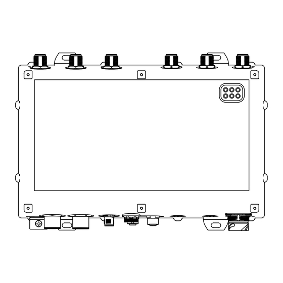
Page 24: Device View
Device view Front view (using the example BAT-FEUWW9ACK99DO5T1SA99) alternatively, depending on For device variants with 2 WLAN modules: device variant 3 × N socket for WLAN module 1 For device variants with 1 WLAN module: Not present alternatively, depending on For device variants with 2 WLAN modules: device variant 3 ×... - Page 25 Ethernet port 1 Combo port – you can use these ports for alternative purposes: SFP slot for 1000 Mbit/s F/O port Design: IP67-V1 connector according to IEC 61076-3-106, variant 1 alternatively, depending on Supply voltage with the characteristic value C and K: device variant 8-pin, X-coded M12 plug for 10/100/1000 Mbit/s twisted-pair port...
-
Page 26: Power Supply
Power supply Only for device variants featuring supply voltage with the characteristic value C, K or W: For redundant and failure-resistant power supply, you have the option of connecting multiple voltage sources in any combination at the same time. The device selects the used voltage source automatically. Switching to a redundant voltage source possibly occurs with a short delay. -
Page 27: Ethernet Ports
Power supply through PoE Your device is a PD (powered device). PSE (power sourcing equipment) connected via a twisted pair cable on the PoE PD port serves as the PoE power supply voltage. The PoE power supply means that no separate power supply is required for your device. -
Page 28: 10/100/1000 Mbit/S Twisted-Pair Connection (Optional)
10/100/1000 Mbit/s twisted pair port Device variants featuring supply voltage with the characteristic value C or K have this port exclusively. The 10/100/1000 Mbit/s twisted pair port offers you the ability to connect network components according to the IEEE 802.3 10BASE-T/100BASE- TX/1000BASE-T standard. -
Page 29: Pin Assignments
1.5.3 Pin assignments M12 4-pin (D coded) Data Positive V Negative V TX− Positive V RX− Negative V M12 8-pin (X-coded) 10/100 Mbit/s 1000 Mbit/s BI_DB+ Negative V RX− BI_DB− Negative V BI_DA+ Positive V TX− BI_DA− Positive V — BI_DC+ —... -
Page 30: Display Elements
Display elements After the working voltage is set up, the software starts and initializes itself. Afterwards, the device performs a self-test. During this process, various LEDs light up. These actions take less than 1 minute. LED display elements for device status and port status WLAN1 ETH1 WLAN2 ETH2... -
Page 31: Device State
1.7.2 Device state These LEDs provide information about conditions which affect the operation of the whole device. P1, P2 (green/red LED) Power Connection is voltage-free green on continuously Voltage present, device is operational. red/green flashing (slowly) Charge lock active. red/green flashing (quickly) Unprotected configuration as no password or the default password is set. -
Page 32: Port State
1.7.3 Port state These LEDs display port-related information. ETH1, ETH2 Data, link status (green/yellow Status of the LAN interfaces LED) No network device connected green on continuously Ethernet connection active Yellow flickering Data traffic Management interfaces 1.8.1 V.24 interface (external management) This interface is designed as an 8-pin, A-coded M12 plug. - Page 33 Pins of the M12 socket Function Description of functions on the device Ground Data terminal ready Transmit data Receive data Data carrier detect Dataset ready Request to send Clear to send Table 2: Pin assignment of the V.24 interface, 8-pin, A-coded M12 socket Pins of the M12 socket on Pin assignment for the connection Pins of the DB9 plug on...
-
Page 34: Aca21-M12 Interface
Note: With the point-to-point WLAN line, the following pins are short-circuited at both ends: 2 (DTR) + 6 (DSR) 7 (RTS) + 8 (DSR) 1.8.2 ACA21-M12 interface This interface offers you the ability to connect the storage medium AutoConfiguration AdapterACA21-M12. -
Page 35: Operation Element (Reset Button)
1.10 Operation element (reset button) The device has a reset button. Note: The reset button is located behind a screwable IP67 pressure- equalization element (Approvals 1 with characteristic value F and G), or IP67 protection cap (Approvals 1 with characteristic value I, K, M and 9). The tightening torque is 4.42 lb-in to 8.85 lb-in (0.5 Nm to 1.0 Nm). -
Page 36: Installation
Installation The devices have been developed for practical application in a harsh industrial environment. On delivery, the device is ready for operation. To protect the exposed uninstalled contacts of the components from dirt, connect the individual system components in a dry and clean working area. The device fulfills the protection class IP65/67 under the following conditions, exclusively: ... -
Page 37: Installing And Grounding The Device
Installing and grounding the device 2.2.1 Installing the device onto or on a flat surface You have the option of attaching the device with suitable hardware to a vertical flat surface. Requirements for the fastening components: The diameter of the fastening components itself is maximum 0.2 in. (5 mm). -
Page 38: Grounding The Device
See “Accessories” on page 66. The clamp diameter of the mast clamp included in the pole mounting set is maximum 2.56 in. (65 mm). For larger pole diameters, you have the option of using tightening straps, which are available in specialized trade. ... -
Page 39: Installing The Antennas
Installing the antennas alternatively, depending on For device variants with 2 WLAN modules: device variant 3 × N socket for WLAN module 1 For device variants with 1 WLAN module: Not present Antenna connection 1 Antenna connection 2 Antenna connection 3 alternatively, depending on For device variants with 2 WLAN modules: device variant... -
Page 40: Connecting The Power Supply And Signal Lines
Connecting the power supply and signal lines WARNING ELECTRIC SHOCK Never insert pointed objects (narrow screwdrivers, wires, etc.) into the device or into the connection terminals for electric conductors. Do not touch the connection terminals. Start connecting the electrical wires only if all the above safety requirements are fulfilled. -
Page 41: Supply Voltage With The Characteristic Value K
2.5.2 Supply voltage with the characteristic value K WARNING ELECTRIC SHOCK Install this device solely in a switch cabinet or in an operating site with restricted access, to which maintenance staff have exclusive access. Failure to follow these instructions can result in death, serious injury, or equipment damage. -
Page 42: Supply Voltage With The Characteristic Value W
2.5.3 Supply voltage with the characteristic value W Type and specification of the Pin assignment on the device supply voltage Nominal voltage DC Minus terminal of the supply 24 V voltage Voltage range DC incl. maximum — tolerances N.C. N.C. 18 V ... -
Page 43: Operating The Device
Operating the device By connecting the supply voltage via a 7/8" plug or a twisted pair cable (Power over Ethernet), you start the operation of the device. 2.6.1 Connecting the power supply through a 7/8" connector Plug the socket into the 7/8" connector on the device. ... -
Page 44: Connecting Data Cables
Connecting data cables 2.7.1 Gigabit combo port 10/100/1000 Mbit/s PoE PD port For further information see “10/100/1000 Mbit/s PoE PD port” on page Connect the data cables according to your requirements. 1000 Mbit/s F/O port For further information see “1000 Mbit/s F/O port”... -
Page 45: Making Basic Settings
Making basic settings The IP parameters must be entered when the device is installed for the first time. The device provides the following options for configuring IP addresses: Entry via V.24 connection Entry with the aid of the HiDiscovery logs on the applications HiDiscovery or Industrial HiVision ... -
Page 46: Configuring The Transmit Power
Configuring the transmit power Note: The operator of a WLAN radio installation must adhere to the applicable transmission threshold values. Use the LANconfig or Webconfig software, which you find on the supplied CD/DVD. Proceed as follows: In the menu tree, open the Configuration > Wireless LAN > General dialog. - Page 47 In the menu tree, open the Configuration > Wireless LAN > General > Physical WLAN settings - Radio dialog. In the “General” tab, click in the “Interface” column the physical WLAN interface to which you connect the antenna. ...
-
Page 48: Resetting The Device
Resetting the device The device has a reset button. Depending on how many seconds you press and hold the reset button, the device executes one of the following actions. ≥ 16 Figure 1: Functions of the reset button a – Resetting the device to the current configuration (soft reset/reboot) b –... -
Page 49: Loading A Customer-Specific Version
Loading a customer-specific version You have the option of loading a customer-specific configuration saved on the device as an alternative to the default configuration. Press and hold the reset button for minimum 16 seconds. If no customer-specific configuration is saved on the device, the device reboots (= soft reset). -
Page 50: Maintenance And Service
Maintenance and service When designing this device, Hirschmann largely avoided using high-wear parts. The parts subject to wear and tear are dimensioned to last longer than the lifetime of the product when it is operated normally. Operate this device according to the specifications. ... -
Page 51: Disassembly
Disassembly Removing the device Disconnect the data cables. Disable the supply voltage. Disconnect the power supply cables and signal lines. Remove the antennas. Disconnect the grounding. Removing an SFP transceiver (optional) To disassemble SFP transceivers, you require the SFP mounting tool available as an accessory . -
Page 52: Technical Data
Technical data General technical data Weight Device variants featuring supply voltage with the approx. 2800 g characteristic value P Device variants featuring supply voltage with the approx. 114.64 oz characteristic value C or K (3250 g) Device variants featuring supply voltage with the approx. - Page 53 Supply voltage with Power supply through a 7/8" connector the characteristic Nominal voltage DC 24 V value W Class 2 Voltage range DC incl. 18 V ... 32 V maximum tolerances Connection type 4-pin, 7/8" connector Power loss buffer > 10 ms at 20.4 V DC Overload current protection at Non-replaceable fuse input...
- Page 54 Dimension drawings 12.24 7.24 2.87 Figure 3: Dimensions of device variants and distance between suspensions. inch 74,37 12.24 2.93 Figure 4: Dimensions of the device variants with impact protection. Installation BAT-F Release 09 08/2015...
- Page 55 inch 7.24 Figure 5: Distances of the suspension with impact protection. Installation BAT-F Release 09 08/2015...
- Page 56 Radio technology Antenna connection For each WLAN module: 3 × N socket Range Up to 12.4 miles (20 km, depending on antenna used, frequency range and data rate) Encryption IEEE 802.11i/WPA2 with passphrase or IEEE 802.1x and hardware-accelerated AES/TKIP ...
- Page 57 Data rate Typical transmission power Typical receive sensitivity 24 Mbps 16 dBm -88 dBm 36 Mbps 15 dBm -84 dBm 48 Mbps 13 dBm -80 dBm 54 Mbps 12 dBm -79 dBm Table 11: Receive sensitivity, transmission power and data rate according to IEEE 802.11a Data rate Typical transmission...
- Page 58 Data rate Typical transmission power Typical receive sensitivity MCS7 15 dBm -72 dBm MCS8 22 dBm -87 dBm MCS9 21 dBm -90 dBm MCS10 22 dBm -86 dBm MCS11 21 dBm -82 dBm MCS12 16 dBm -79 dBm MCS13 16 dBm -75 dBm MCS14 15 dBm...
- Page 59 Data rate Typical transmission power Typical receive sensitivity MCS12 18 dBm -81 dBm MCS13 15 dBm -77 dBm MCS14 15 dBm -75 dBm MCS15 14 dBm -73 dBm MCS16 21 dBm -92 dBm MCS17 21 dBm -91 dBm MCS18 21 dBm -89 dBm MCS19 21 dBm...
- Page 60 Data rate Typical transmission Typical receive sensitivity power 1Mbps 19 dBm -94 dBm 11Mbps 19 dBm -94 dBm Table 17: Receive sensitivity, transmission power and data rate according to IEEE 802.11b Data rate Typical transmission Typical receive sensitivity power 06Mbps 22 dBm -94 dBm 09Mbps...
- Page 61 Data rate Typical transmission power Typical receive sensitivity MCS14 15 dBm -73 dBm MCS15 15 dBm -72 dBm MCS16 23 dBm -87 dBm MCS17 23 dBm -90 dBm MCS18 23 dBm -86 dBm MCS19 23 dBm -82 dBm MCS20 16 dBm -79 dBm MCS21 17 dBm...
- Page 62 Data rate Typical transmission power Typical receive sensitivity MCS19 8 dBm -84 dBm MCS20 3 dBm -81 dBm MCS21 2 dBm -77 dBm MCS22 1 dBm -75 dBm MCS23 1 dBm -73 dBm Table 20: Receive sensitivity, transmission power and data rate according to IEEE 802.11n and for the 5.180 GHz –...
- Page 63 Network range Note: The line lengths specified for the transceivers apply for the respective fiber data (fiber attenuation and BLP/dispersion). Product Wave Fiber System Example Fiber code length attenuatio for F/O line attenuatio dispersion M-SFP-... length -SX/LC... MM 850 nm 50/125 µm 0-7.5 dB 0-550 m...
- Page 64 Scope of delivery Number Article 1 × Device 1 × Installation user manual 1 × CD/DVD with manual 1 × Terminal cable: M12 connector, 8-pin on DB9 socket 3 × per WLAN module 3-dBi dipole dual-band antennas for initial operation 2 ×...
- Page 65 Number Article 1 × Device 1 × Installation user manual 1 × CD/DVD with manual 1 × Power supply plug, for cable diameters of 0.24 to 0.32 in. (6 to 8 mm; model dependent on the characteristic value of the socket) You find power supply plugs with a larger thread here: “Accessories”...
- Page 66 Accessories Note that products recommended as accessories may have different characteristics to those of the device, which may limit the application range of the overall system. For example, if you add an accessory with IP 20 to a device with IP 65, the IP of the overall system is reduced to 20. To sustain the IP65/67 suitability for your device, use the accessories with IP65/67 properties exclusively.
- Page 67 Other accessories Order number AutoConfiguration Adapter, M12 943 913-001 BAT-ANT-N-3AGN-IP67 (10 pcs.) 942 110-001 BAT Protector 943 903-373 EM12S, field-attachable M12 plug for Fast Ethernet data cables 934 445-001 Pole mounting set for OpenBAT device 942 116-001 Network management software Industrial HiVision 943 156-xxx PoE power supply unit PC150/36V/48V-IP67, working voltage 943 968-001...
- Page 68 Underlying technical standards Name ATEX 95 (94/9/EG) ATEX – Intended use of equipment and protection systems in in potentially explosive areas. CSA 22.2 No. 60950-1 Information Technology Equipment – Safety – Part 1: General Requirements ECE Nr. 10 E type approval for use in vehicles EN 300 328 Electromagnetic compatibility and radio spectrum matters (ERM) - bandwidth transfer systems - data transmission equipment...
- Page 69 The device has an approval based on a specific standard only if the approval indicator appears on the device casing. If your device has a shipping approval according to Germanischer Lloyd, you find the approval mark printed on the device label. You will find out whether your device has other shipping approvals on the Hirschmann website under www.hirschmann.com...
-
Page 70: A Further Support
Contact our support at https://hirschmann-support.belden.eu.com Contact us in the EMEA region at Tel.: +49 (0)1805 14-1538 Email: hac.support@belden.com in the America region at Tel.: +1 (717) 217-2270 Email: inet-support.us@belden.com in the Asia-Pacific region at ... - Page 71 Installation BAT-F Release 09 08/2015...
Need help?
Do you have a question about the Hirschmann BAT-F Series and is the answer not in the manual?
Questions and answers