Table of Contents
Advertisement
INSTRUCTIONS
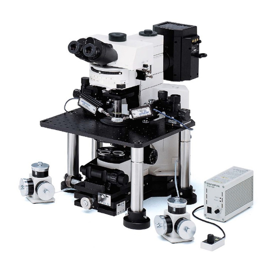
BX61WI
FIXED-STAGE MOTORIZED
UPRIGHT MICROSCOPE
This instruction manual is for the Olympus Fixed-Stage Motorized Upright Microscope Model BX61WI.
To ensure the safety, obtain optimum performance and to familiarize yourself fully with the use of
this microscope, we recommend that you study this manual thoroughly before operating the micro-
scope. Retain this instruction manual in an easily accessible place near the work desk for future
A X 6 1 1 8
reference.
Advertisement
Table of Contents

Subscribe to Our Youtube Channel
Related Manuals for Olympus BX61WI


Summary of Contents for Olympus BX61WI
- Page 1 FIXED-STAGE MOTORIZED UPRIGHT MICROSCOPE This instruction manual is for the Olympus Fixed-Stage Motorized Upright Microscope Model BX61WI. To ensure the safety, obtain optimum performance and to familiarize yourself fully with the use of this microscope, we recommend that you study this manual thoroughly before operating the micro- scope.
-
Page 3: Table Of Contents
BX61WI CONTENTS Correct assembly and adjustments are critical for the microscope to exhibit its full performance. If you are going to assemble the microscope yourself, please read Chapter 9, “ASSEMBLY” (pages 42 to 49) carefully. For the modules provided with instruction manuals, also read the assembly procedures in their instruction manuals. - Page 4 OTHER OBSERVATION METHODS 24-35 5-1 Differential Interference Contrast Observation................24-28 Attaching the Analyzer Attaching the Polarizer Attaching the DIC Prisms (for Revolving Nosepiece) Attaching the DIC Prisms (for Condenser) Adjusting the Polarizer Position Observation Method 5-2 Reflected Light Fluorescence Observation ....................29 5-3 Infrared Light (IR)/Differential Interference Contrast (DIC) Observation ....
- Page 5 This microscope employs a UIS (Universal Infinity System) optical design, and should be used only with modules designed for the BX2 series (which belong to the Olympus BX series). For the applicable modules, please consult Olympus or the latest catalogues. Less than optimum performance may result if inappropriate module combinations are used.
- Page 6 Olympus-authorized agent). 8. Always use the power cord provided by Olympus. If the proper power cord is not used, product safety performance cannot be warranted. 9. Always ensure that the grounding terminal of the microscope and that of the wall outlet are properly connected.
- Page 7 2. The U-SWTR-2 super-widefield observation tube (FN 26.5) cannot be used with the BX61WI microscope. 3. The BX61WI microscope can be used with an intermediate attachment (such as a BX-RFAA, BX-URA2 or BX-RFA reflected light illuminator, U-ECA or U-CA magnification changer, etc.).
- Page 8 }The modules shown below are only the representative modules. As there are other modules which can be combined with the microscope but are not shown below, please also refer to the latest Olympus catalogues or your dealer. The Z board combined with the BX61WI must always be the U-ZPCB(T2). Also note that the DIP switch CAUTION setting should be changed when the Z board is used (see page 44).
- Page 9 BX61WI CONTROLS }If you have not yet assembled the microscope, read Chapter 9, “ASSEMBLY” (pages 42 to 49). Reflected light fluorescence illuminator (See the separately provided instruction manual.) Light path selector knob (Page 20) Interpupillary distance scale (Page 19) Reflected light mercury lamp housing (See the separately provided instruction manual.)
- Page 10 Left Side View of Microscope Frame Focus adjustment knob (Page 15) Objective escape/return button (Page 16) F/C button (Page 16) F: Fine adjustment C: Coarse adjustment Light Preset switch (Page 14) Frost filterinsertion/removal lever (Page 16) Lamp ON-OFF switch Filter Turret * Accepts the combination of a Polarizer rotating dials polarizer push ring and a 32 mm...
- Page 11 BX61WI Revolving Arm WI-NPA # Note that the revolving arm can be mounted only before the reflected light illuminator or transmitted light arm and the IX-SVL2 stage are mounted (page 45). }This revolving arm accepts the U-SLRE, WI-SNPXLU2 or WI-SRE3 revolving nosepiece.
- Page 12 Long-WD Universal Condenser WI-UCD Aperture iris diaphragm lever (Page 22) Quarter-wave plate clamping knob Turret (4 positions) Optical element index mount (Page 26) Quarter-wave plate rotation DIC prism replacement cover ring (Page 28) Long-WD DIC Condenser WI-DICD DIC prism (Large) mount position DIC prism (Small) adapter Aperture iris diaphragm lever (Page 22)
- Page 13 BX61WI Long-WD Oblique Condenser WI-OBCD Aperture iris diaphragm lever (Page 22) Oblique iris insertion/removal knob (Page 22) High-Resolution DIC Prism A WI-DICTHRA2 DIC Prism WI-DICT2 }This prism can be mounted in the DIC prism position of the WI-SNPXLU2 or WI-SRE3.
- Page 14 }The following modules are required to eliminate electrical noise, which may affect the potential measurement data during patch clamping. Halogen Lamp Power Supply TH4 (See the separately provided instruction manual for details.) Hand Switch TH4-HS Focus Adjustment Knob Interface U-IFFH Microscope FRAME connector U-FH connector BX-UCB connector...
- Page 15 Z-focusing motor ON/OFF OFF: Electrical noise reduction Escape/return objective Shutter IN/OUT Condenser top lens IN/OUT Not used with the BX61WI. Up/down operation for brightness ad- The function name can be written justment, objective, etc. in the blank area using an oil-ink pen.
- Page 16 TRANSMITTED LIGHT BRIGHTFIELD OBSERVATION PROCEDURE }The following flow shows the operating procedure for the transmitted light brightfield observation which is the basic observation method of this microscope. The operating procedures for DIC observation, fluorescence DIC observation and IR DIC observation will be described separately in Chapter 5, “OTHER OBSERVATION METHODS” on page 24. (Controls Used) (Page) @Main switch...
- Page 17 BX61WI (Note) Controls with numbers inside can perform the same functions as the controls with numbers inside ¦. However, the function of control is not available when the U-FH is in use. Control Box BX-UCB * The U-ZPCB (T2) Z board can be mounted here.
-
Page 18: Using The Controls
USING THE CONTROLS 4-1 Microscope Frame Voltage Indication (Fig. 3) 1. Press the light intensity control button 1 to increase the voltage and make illumination brighter. Pressing the button 2 makes the illumination darker. 2. The numerals to the left of the lamp voltage indicator LEDs 3 indicate the reference values of the voltages. -
Page 19: Focusing Block
BX61WI Using the Filter Turret (Fig. 5) }Filters with a diameter of 32 mm can be inserted in positions 1 to 4. 1. Filter positions 1 2 are rotatable. When the 32PO or 32POIR polarizer is placed in either position, the polarizer can be fixed by a push ring. -
Page 20: Using The Frost Filter Insertion/Removal Lever
F/C Button (Fig. 7) }The F/C button switches the function of the focus adjustment knob 1 and focus adjustment dial between F (fine) and C (coarse). (For safety, the F/C button is set automatically to F at the moment the main switch of the BX-UCB control box is set to “... -
Page 21: Stage (Ix-Svl2)
BX61WI 4-3 Stage (IX-SVL2) Placing the Specimen (Fig. 11) 1. Place the specimen on the center of the stage. }The optional stage center plate (IX-CP50) makes it possible to observe a wide range of a big petri dish, etc. (Central hole diameter: 50 mm) Fig. -
Page 22: Revolving Nosepiece
(Fig. 15) # The light shielding sheet provided with the reflected light fluorescence illuminator is too small to be used with the BX61WI. Always use the light shielding sheet provided with the BX61WI. }During fluorescence observation using a low-magnification objective, the fluorescence image may be deteriorated due to light reflected from the condenser or the surroundings. -
Page 23: Observation Tube
BX61WI 4-5 Observation Tube Adjusting the Interpupillary Distance (Fig. 18) While looking through the eyepieces, adjust for binocular vision until the left and right fields of view coincide completely. The index dot · indicates the interpupillary distance. }Note your interpupillary distance so that it can be quickly duplicated. -
Page 24: Selecting The Light Path Of Trinocular Tube
Using Eyepiece Micrometer Disks (Fig. 22) Eyepiece micrometer disks can be inserted into the WHN10X-H (or WHN10X) eyepieces. Use 24 mm dia. x 1.5 mm micrometer disks. Following Fig. 22, remove the micrometer mounting frame 2 from the eyepiece and place a micrometer disk 1 into the mounting frame so that the surface with the model indication faces downward. -
Page 25: Condenser
BX61WI 4-6 Condenser Centering the Condenser (Figs. 24 to 26) 1. Set the aperture iris diaphragm lever 1 to the open position. (Fig. 25) 2. Set the field iris diaphragm ring 2 to the open position ( ¦). (Fig. 24) 3. - Page 26 Aperture Iris Diaphragm Aperture iris 70-80% diaphragm image · The aperture iris diaphragm determines the numerical aperture of the 30-20% illumination system. Matching the numerical aperture of the illumination system with that of the objective provides better image resolution and contrast, and also increases the depth of focus.
-
Page 27: Water Immersion Objectives
BX61WI 4-7 Water Immersion Objectives Using Water Immersion Objectives (Figs. 29 & 30) }When the UMPlanFl-W series, LUMPlanFl-W series or XLUMPlanFl20XW objective is used, cultured tissue specimens which are often very thick can be observed by immersing the specimen, objective front lens and manipulator extremity in a medium (water) with the same refractive index. -
Page 28: Other Observation Methods
2. Remove the cover to expose the polarizer and remove it together with the frame. (Retain the removed polarizer carefully for future use with a microscope other than the BX61WI. 3. Attach the polarizer cover to the original position. Fig. 33... -
Page 29: Attaching The Dic Prisms (For Revolving Nosepiece)
BX61WI Attaching the DIC Prisms (for Revolving Nosepiece) (Fig. 34) }The DIC prisms for use in the revolving nosepiece include the WI- DICTHRA2 (high-resolution type) and WI-DICT2 (middle-contrast type). The revolving nosepieces in which a DIC prism can be inserted are the WI- SRE3 and WI-SNPXLU2. - Page 30 With the WI-UCD Condenser (Figs. 35 - 37) }When selecting the brightfield (BF) light path using the WI-UCD, leave one DIC prism (large) mount position empty. 1. Remove the WI-UCD condenser from the microscope frame. 2. Remove the condenser cover 1 by loosening the retaining screws 2 using a coin, etc.
- Page 31 BX61WI With the WI-DICD Condenser (Fig. 38) }The WI-DICD should be attached after completing the polarizer position as described in item 1. Remove the WI-DICD condenser from the microscope frame. 2. Remove the two clamping screws 1 using the Allen screwdriver provided with the microscope, then place the top of the condenser upside down.
-
Page 32: Observation Method
4. Remove the eyepiece from the eyepiece sleeve, look into the sleeve, turn the polarizer rotation dial 2 so that the black interference stripe (Fig. 40) is darkest, and tighten the clamping knob 3. 5. Engage an objective (as low-magnification as possible) in the light path, attach the condenser and bring the specimen surface into focus. -
Page 33: Reflected Light Fluorescence Observation
2. To reduce the influence of heat on the specimen, stop down the field iris diaphragm of the BX61WI microscope as small as possible. However, the contrast may sometimes be improved by circumscribing the field iris diaphragm with the field... - Page 34 3. To enable IR observation, the following modules should be replaced with those based on the IR specifications. IR TV camera Video contrast device such as (Note) TV adapter the ARGUS10.20 by Hamamatsu Photonics, monochrome video monitor Trinocular tune U-TR30IR U-ETR3 U-TR30-2 Objectives...
- Page 35 BX61WI c) Combination using C-mount adapter IR system (visible light to 1000 nm) C-mount adapter IR system U-TVCAC C-mount TV camera U-PMTVC2XIR (IR specification model) U-PMTVC4XIR d) Combination using U-CA or U-ECA intermediate tube One of these intermediate tubes can be used only in combination with the U-ETR3 or U-TR30IR trinocular tube. The TV adapter used in this combination should be one of that used in a), b) or c).
-
Page 36: Dic Observation Using Ir
DIC Observation Using IR Since IR light is harmful to your eyes, use the monitor observation whenever possible even in adjustments. 1. First, perform adjustments for DIC observation without using IR. }Do not mount the IR filter and see Section 5-1, “Differential Interference Contrast Observation” on page 24. IMPORTANT ·... -
Page 37: Macro Reflected Light Fluorescence Observation
BX61WI 5-4 Macro Reflected Light Fluorescence Observation }The macro reflected light fluorescence observation makes possible bright, low-magnification fluorescence observation by combining low-magnification fluorescence mirror units and fluorescence objective. Introduction 1. For the low-magnification fluorescence observation, use a low-magnification fluorescence mirror units. - Page 38 Attaching the Modules (Figs. 45 & 46) Low-Magnification Fluorescence Mirror Units }Select the suitable mirror units for purpose of observation by referring to page 35. }If you want to fabricate optional mirror units, see page 35. · Mount the mirror units as indicated in the instruction manual of your reflected light fluorescence system.
-
Page 39: Filter Characteristics Of Fluorescence Mirror Units
BX61WI Filter Characteristics of Fluorescence Mirror Units Excitation Mirror Unit Dichroic Mirror Excitation Filter Barrier Filter Application Method U-MGFP/XL BA510IF For EGFP, S65T, RSGFP. DM505 BP460-490 (U-MGFPA/XL is for fluorochrome separation.) U-MGFPA/XL BA510-550 1. IB excitation (wide bandwidth) U-MGFP/XL 2. IB excitation (wide bandwidth) -
Page 40: Troubleshooting Guide
Under certain conditions, performance of the microscope may be adversely affected by factors other than defects. If problems occur, please review the following list and take remedial action as needed. If you cannot solve the problem after checking the entire list, please contact your local Olympus representative for assistance. Problem... - Page 41 BX61WI Problem Cause Remedy Page e) Visibility of observed image is poor. The objective in use is not designed for Replace with a specified objective for · Image is not sharp. UIS series. UIS series. · Contrast is poor. The condenser is set to too low a posi- Adjust the condenser height.
- Page 42 Problem Cause Remedy Page 2. Electrical System a) The bulb intermittently lights and The bulb is nearly burnt out.. Replace the bulb. goes out. A cord or connector is not properly con- Connect cords and plugs securely. – nected. b) The lamp bulb burns out soon after The bulb in use is not the specified lamp.
-
Page 43: Specifications
BX61WI SPECIFICATIONS Item Specification 1. Optical system UIS (Universal Infinity System) optical system (Infinity correction) 2. Illumination system Transmitted Kohler illumination built in (FN 22) 12 V, 100 W long-life halogen bulb (pre-centered) 12V100WHAL-L (PHILIPS 7724) or 12 V, 50 W long-life halogen bulb (precentered) 12V50WHAL-L (LIFE JC) Average life time: Approximately 2000 hr. - Page 44 Item Specification 8. Operating environment · Indoor use · Altitude: Max. 2000 m · Ambient temperature: 10° to 40°C (50°F to 104°F) · Maximum relative humidity: 80% for temperatures up to 31°C (88°F), decreasing linearly through 70% at 34°C (93°F), 60% at 37°C (99°F), to 50% relative humidity at 40°C (104°F) ·...
-
Page 45: Optical Characteristics
Number of aperture Mechanical tube length NOTE Color band Water immersion Refer to the latest catalogue or consult your local Olympus indicator (white) representative for the updated information on the eyepieces and objectives that can be combined with this microscope. Eyepieces... -
Page 46: Assembly
The module numbers shown in the following diagram are merely the typical examples. For the modules with which the module numbers are not given, please consult your Olympus representative or the latest catalogues. # When assembling the microscope, make sure that all parts are free of dust and dirt, and avoid scratching any parts or touching glass surfaces. - Page 47 BX61WI Revolving Arm, Revolving Nosepiece, Objectives Light shielding tube Turret Reflected light fluorescence Light shielding tube illuminator (Transmitted light BX-RFAA arm adapter) BX-URA2 BX-RFA Transmitted light arm Light shielding tube BX-ARM The revolving nosepiece clamping screw is not used. Revolving arm...
- Page 48 9-2 Detailed Assembly Procedures # Be always sure to use the U-ZPCB(T2) Z board which is designed to be compatible with the BX61WI. The following phenomena will occur with the U-ZPCB even though the correct setup is performed. · The rotation direction of the focus adjustment knob is opposite to the actual movement direction of the objectives.
- Page 49 BX61WI }When performing observation on a desktop, attach the provided rubber feet (x 4) to the front (x 2) and rear (x 2) parts on the bottom of the base. Note that the rubber feet are not necessary when installing the microscope on an anti-vibration bench.
- Page 50 3. Engage the objective on the back side in the light path. Adjust focusing, read the scale indication of the fine adjustment knob and obtain the difference from the value read in step 2 above. 4. The objective to use the washer is determined by the rotation direction of the fine adjustment dial 2.
- Page 51 BX61WI Attaching the Condenser (Fig. 54) # When attaching a condenser other than the WI-UCD, remove the upper limit stopper screw 1 of the condenser holder with an Allen screwdriver. }In DIC observation, attach the DIC prism (for condenser) before attaching the condenser onto the microscope frame (page 25).
- Page 52 Attaching the Halogen Lamp Housing (Figs. 56 to 59) Attaching the Halogen Bulb }The applicable lamp bulb model is the 12V100WHAL-L (PHILIPS 7724) or the 12V50WHAL-L (LIFE JC). 1. Fully loosen the clamping screw 1 at the top of the lamp housing using the Allen screwdriver provided with the microscope frame.
- Page 53 BX61WI Attaching the Cross Stage (Figs. 60 & 61) }When using a WI-XYS bridge stage, attach it by referring to its instruction manual. 1. Align the two WI-FSH fixed stage adapters 1 with the front of the micro- scope frameand clamp the adapters by tightening the hex-socket screws from the bottom side using the Allen wrench provided with the micro- scope frame.
- Page 54 MEMO...
- Page 56 Postfach 10 49 08, 20034, Hamburg, Germany OLYMPUS AMERICA INC. 2 Corporate Center Drive, Melville, NY 11747-3157, U.S.A. OLYMPUS SINGAPORE PTE LTD. 491B River Valley Road, #12-01/04 Valley Point Office Tower, Singapore 248373 OLYMPUS UK LTD. 2-8 Honduras Street, London EC1Y OTX, United Kingdom.
Need help?
Do you have a question about the BX61WI and is the answer not in the manual?
Questions and answers