Table of Contents
Advertisement
INSTRUCTIONS
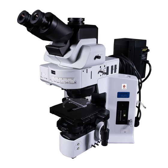
BX61
MOTORIZED SYSTEM
MICROSCOPES
This instruction manual is for the Olympus Motorized System Microscopes Models BX61 and BX62.
To ensure the safety, obtain optimum performance and to familiarize yourself fully with the use of
this microscope, we recommend that you study this manual thoroughly before operating the micro-
scope. Retain this instruction manual in an easily accessible place near the work desk for future
reference.
A X 7 6 1 1
Advertisement
Table of Contents

Related Manuals for Olympus BX61


Summary of Contents for Olympus BX61
- Page 1 MOTORIZED SYSTEM MICROSCOPES This instruction manual is for the Olympus Motorized System Microscopes Models BX61 and BX62. To ensure the safety, obtain optimum performance and to familiarize yourself fully with the use of this microscope, we recommend that you study this manual thoroughly before operating the micro- scope.
-
Page 3: Table Of Contents
BX61 CONTENTS Correct assembly and adjustments are indispensable to allow the microscope manifest its full performance. If you are going to assemble the microscope by yourself, please read chapter 7, “ASSEMBLY” (pages. 29 to 32). IMPORTANT — Be sure to read this section for safe use of the equipment. —... - Page 4 This device complies with the requirements of directive 98/79/EC concerning in vitro diag- nostic medical devices. CE marking means the conformity to the directive. NOTE: This equipment has been tested and found to comply with the limits for a Class A digital device, pursuant to Part 15 of the FCC Rules.
-
Page 5: Safety Precautions
IMPORTANT Each of these microscopes employs a UIS2/UIS (Universal Infinity System) optical design, and should be used only with modules designed for the BX2 series (which belong to the Olympus BX series microscopes) and objectives/eyepieces for the UIS series. For the applicable module, please consult Olympus or the catalogues. Less than optimum performance may result if inappropriate accessories are used. - Page 6 # The microscope also incorporate a fuse (this should be replaced by the manufacturer or an authorized agent). 9. Always use the power cord provided by Olympus. If no power cord is provided, please select the proper power cord by referring to the section “PROPER SELECTION OF THE POWER SUPPLY CORD”...
-
Page 7: Maintenance And Storage
# Damage to the microscope will occur if you grasp it by the stage, focus adjustment knob or binocular section of the observation tube. 4. The BX61 series can be used with up to two intermediate attachments including a U-CA magnification changer, U-EPA2 eyepoint adjuster, etc. - Page 8 NOMENCLATURE }If you have not yet assembled the microscope, read chapter 7, “ASSEMBLY” (pages 29 to 32). Transmitted light specification models Light path selector knob (Page 17) Condenser height adjustment screw (Page 19) Interpupillary distance adjustment scale (Page 16) Allen screwdriver (accommodation position) Diopter adjustment Lamp voltage indicator...
- Page 9 BX61 Base Focus adjustment knob (Page 11) Stage escape button UCB connector (Page 12) Stage UP button (Page 12) Light Preset switch (Page 8) F/C button (Page 11) Stage DOWN button (Page 12) Lamp ON-OFF switch Reflected light specification models * For the reflected illuminators and reflected lamp housings, please also refer to their instruction manuals.
-
Page 10: Observation Procedure
TRANSMITTED LIGHT BRIGHTFIELD OBSERVATION PROCEDURE (Controls Used) (Page) @Main switch “ I ” (ON) Set the main switch to “ I ” (ON). ²Lamp ON-OFF switch ON Select the transmitted light and adjust the ³Transmitted/reflected light switch (P. 8) brightness. |Brightness adjustment buttons (P. - Page 11 BX61 … ™ Use the Allen screwdriver. Œ ‹ ³ † › š Use the Allen screwdriver. ‡ œ ‰ ƒ Ÿ Control Box* BX-UCB ‰ * Set the Z-board or AF-board. For the setup and installation of the Z-board, refer to ²...
-
Page 12: Using The Controls
USING THE CONTROLS 3-1 Base Voltage Indication (Fig. 4) ³ 1. Press the Brightness adjustment button @ to increase the voltage and make illumination brighter. Pressing the button ² makes the illumination darker. 2. The numerals on the left of the lamp voltage LEDs ³ indicate the approximate voltage. - Page 13 LBD (for color balancing, daylight filter) Fig. 6 OP (optional) filter set* * Ask your Olympus representative to mount the filters. Mounting a Single Filter (Fig. 7) ƒ A filter with a diameter of 45 mm ƒ can be placed on the filter mount on the base.
- Page 14 Mounting the Filter Cassette 1. Fully loosen the filter cassette clamping screw †. (Fig. 9) ‡ 2. Align the key ‡ on the bottom surface of the filter cassette with the positioning slot Š on the filter mount, then snap the filter cassette into ‰...
-
Page 15: Focusing Block
BX61 3-2 Focusing Block #If the substage is not installed in the correct position, it may deviate from the coverage range of the damper spring of the objective and damage the specimen. ² Ensure that the top surface @ of the substage is flush with the bottom surface of the notch ²... -
Page 16: Stage Up/Down Buttons
Stage UP/DOWN Buttons (Fig. 15) !When lowering the stage, be careful not to have your hand caught between the bottom of the condenser and the base. · Press the stage UP button @ to raise the stage and press the stage DOWN button ²... -
Page 17: Stage
BX61 3-3 Stage }The following description deals with biological specimens. When observing a metallurgic specimen, it is more convenient to replace the special stage or slide holder with the stage plate. (For details, refer to the instruction manual for the BX-RLAA.) ²... -
Page 18: Rotating The Stage
Adjusting the X/Y-Axis Knob Tension (Fig. 20) 1. Hold the X-axis knob @ and slide up the Y-axis knob ² up to expose the ² adjustment knobs. 2. Turning the X-axis adjustment knob ³ or Y-axis adjustment knob | clock- wise (in the direction of the arrow) increases the rotation tension and ³... -
Page 19: Adjusting The Stage Height
BX61 Adjusting the Stage Height (Figs. 22 & 23) }By lowering the position of the substage, the microscope will accommo- date specimens with maximum height of 35 mm. This is useful when observing metallurgical specimens and other thick objects. 1. Press the stage DOWN button @ to lower the stage to the lower limit, then remove the stage from the microscope. -
Page 20: Observation Tube
3-4 Observation Tube Adjusting the Interpupillar Distance (Fig. 24) While looking through the eyepieces, adjust for binocular vision until the left and right fields of view coincide completely. The index dot · indicates the interpupillary distance. }Note your interpupillary distance so that it can be quickly duplicated. Fig. -
Page 21: Using The Eyepiece Micrometer Disk
TV/photography 100% for binocu- 100% for TV/ lar eyepieces photography 50% for binocular Fig. 29 eyepieces, 50% for U-TR30NIR* TV/photography * With the infrared trinocular tube, infrared observation up to 1000 nm is possible. For details, consult your Olympus representative. -
Page 22: Adjusting The Tilt
U-TTBI is the inverted image model, and both models are of the same size. # The intermediate attachments that can be combined with the U- TTBI are limited. For details, please contact Olympus. Fig. 31... -
Page 23: Condenser
BX61 3-5 Condenser Centering the Condenser (Figs. 32 & 33) 1. Fit the Allen screwdriver @ into the condenser height adjustment screw and turn the tool counterclockwise to raise the condenser to its upper limit. 2. Focus on the specimen using the 10X objective. - Page 24 Aperture Iris Diaphragm (Figs. 34 & 35) Aperture iris diaphragm image 70-80% · The aperture iris diaphragm determines the numerical aperture of the illumination system. It has an effect of adjusting image resolution and 30-20% contrast. Stopping down the aperture iris diaphragm increases the depth of focus.
-
Page 25: Immersion Objectives
BX61 3-6 Immersion Objectives # Be sure to use the provided Olympus Immersion oil. Using Immersion Objectives (Fig. 36) 1. Focus on the specimen using all objectives, starting from the lowest- power objective to higher-power objectives. 2. Press the stage escape button to lower the stage, then place a drop of provided immersion oil onto the specimen at the area to be observed. -
Page 26: Troubleshooting Guide
Under certain conditions, performance of the unit may be adversely affected by factors other than defects. If problems occur, please review the following list and take remedial action as needed. If you cannot solve the problem after checking the entire list, please contact your local Olympus representative for assistance. Problem... - Page 27 BX61 Problem Cause Remedy Page e) Visibility is poor. Correction collar on correction collar While focusing, turn the correction col- · Image is not sharp. equipped objective is not properly ad- lar to find the best position. · Contrast is poor.
- Page 28 Problem Cause Remedy Page c) Coarse adjustment will not go all Condenser holder is too low. Raise condenser holder. the way down. d) Objective makes contact with speci- Specimen is mounted upside down. Mount specimen correctly. – men before focus is obtained. 4.
-
Page 29: Specifications
BX61 SPECIFICATIONS Item Specification 1. Optical system UIS2/UIS (Universal Infinity System) optical system (featuring infinity correction) Built-in transmitted Koehler illumination 2. Illumination 12 V , 100 W long-life halogen bulb (pre-centered) 12 V 100 W HAL-L (PHILIPS 7724) or 12 V , 50 W long-life halogen bulb (pre-centered) 12 V 50 W HAL-L (LIFE JC) (Average life time: Approx. - Page 30 Item Specification U-UCD8A 7. Condenser Type U-AAC U-SC3 Motorized, achromat/ Achromat/aplanat Swing-out aplanat, swing-out N.A. 1.40 0.9 - 0.1 1.4 - 0.2 Aperture iris With numerical aperture scale diaphragm Objective 1.25X (for FN 22 10X - 100X range widefield), 2X - 100X (for FN 26.5 (for FN 26.5 super 2X - 100X (for FN 26.5 super widefield)
-
Page 31: Optical Characteristics <
Iris: Iris diaphragm NOTE length Field number (FN) Refer to the latest catalogue or consult your local Olympus representative for the updated information on the eyepieces Color band Cover glass thickness and objectives that can be combined with this microscope. - Page 32 Eyepiece Optical Cover Reso- WHN10X (FN22) glass character Magnifi- W.D. N.A. thick- lution Remark Depth of cation (mm) Field of ness (μm) focus Total mag. view Objective (mm) (μm) PlanFl Plan Semi Series 100X 0.95 0.20 0.14-0.20 0.35 1000X 0.22 Correction collar Apochromat (FN26.5)
-
Page 33: Assembly
Allen wrench ( ) for clamping the internal screws (to ensure the performance, we recommend that you have your Olympus representative assemble or remove this module). - Page 34 Setup and Installation of the Z-Board }The on-board DIP switches on the Z-board have been set up for the BX61 or BX62 (all of switches S1, S2 and S3 are set to OFF). Changing the Settings of On-Board DIP Switches (Fig. 38) # Leave all other DIP switches than those mentioned below in the OFF positions.
- Page 35 BX61 Installing the Halogen Bulb (Figs. 40 - 42) }Use only the designated bulb 12V100WHAL-L (PHILIPS 7724) or 12V50WHAL-L (LIFE JC). 1. Fully loosen the lamp housing clamping screw @ on top of the lamp ² housing cover with the provided Allen screwdriver.
- Page 36 Attaching the Condenser (Fig. 44) ² }This operation necessitates the operation of the motorized focusing. Con- nect the cables and set the main switch to “ I ” (ON) before proceeding to the following. 1. Press the stage UP button @ to raise the stage to its upper limit. 2.
-
Page 37: Proper Selection Of The Power Supply Cord
If no power supply cord is provided, please select the proper power supply cord for the equipment by referring to “ Specifications ” and “ Certified Cord ” below: CAUTION: In case you use a non-approved power supply cord for Olympus products, Olympus can no longer warrant the electrical safety of the equipment. - Page 38 Table 2 HAR Flexible Cord APPROVAL ORGANIZATIONS AND CORDAGE HARMONIZATION MARKING METHODS Alternative Marking Utilizing Printed or Embossed Harmoniza- Black-Red-Yellow Thread (Length tion Marking (May be located on Approval Organization of color section in mm) jacket or insulation of internal wir- ing) Black Yellow...
- Page 40 Shinjuku Monolith, 3-1, Nishi Shinjuku 2-chome, Shinjuku-ku, Tokyo, Japan Wendenstraße 14-18, 20097 Hamburg, Germany 3500 Corporate Parkway, P.O. Box 610, Center Valley, PA 18034-0610, U.S.A. One Corporate Drive, Orangeburg, NY 10962, U.S.A. 491B River Valley Road, 12-01/04 Valley Point Office Tower, Singapore 248373 31 Gilby Road, Mount Waverley, VIC., 3149, Australia 5301 Blue Lagoon Drive, Suite 290 Miami, FL 33126, U.S.A.
Need help?
Do you have a question about the BX61 and is the answer not in the manual?
Questions and answers