Table of Contents
Advertisement
Quick Links
NXP Semiconductors
User's Guide
Freedom Board for Kinetis K28F
(FRDM-K28F)
1. Introduction
The Freedom development platform is a set of software
and hardware tools for evaluation and development. It
is ideal for rapid prototyping of MCU-based
applications. The Freedom K28 board (FRDM-K28F)
is a simple yet sophisticated design featuring the
Kinetis K series MCU built upon the ARM
®
Cortex
-M4 core which features a Floating-Point Unit
(FPU).
FRDM-K28F can be used to evaluate the K27 and K28
Kinetis K series MCUs. The FRDM-K28F board
features the MK28FN2M0VMI15 MCU which features
a maximum operating frequency of 150 MHz, 2 MB
flash, 1 MB RAM, high-speed and full-speed USB
controller with available crystal-less operation,
SDRAM controller, secure digital host controller,
QuadSPI controller, and analog and digital peripherals.
The FRDM-K28F hardware is form-factor compatible
with the Arduino™ R3 pin layout, providing a broad
range of expansion board options. The on-board
interface includes a 6-axis digital accelerometer and
magnetometer, RGB LED, FlexIO socket, SD card
interface, mobile SDRAM memory, and external serial
flash memory.
© 2017 NXP B.V.
Arrow.com.
Downloaded from
Document Number: FRDMK28FUG
1.
Introduction ........................................................................ 1
2.
FRDM-K28F hardware overview ...................................... 2
3.
FRDM-K28F hardware description .................................... 4
3.1.
Power supply ........................................................... 4
3.2.
................................................................................ 7
4.
MCU .................................................................................. 9
®
5.
Clocking ........................................................................... 10
6.
Universal Serial Bus (USB) ............................................. 11
7.
VBAT ............................................................................... 12
8.
Accelerometer and magnetometer .................................... 13
9.
RGB LED......................................................................... 14
10. Serial port ......................................................................... 15
11. QuadSPI memory ............................................................. 15
12. Mobile SDRAM memory ................................................. 15
13. Secure Digital (SD) card .................................................. 15
14. FlexIO socket ................................................................... 16
15. Reset................................................................................. 17
16. Push-button switches ........................................................ 17
17. Visible light sensor ........................................................... 18
18. Debug ............................................................................... 19
19. Input/output connectors .................................................... 19
20. Arduino compatibility ...................................................... 20
21. Jumper table ..................................................................... 20
22. References ........................................................................ 21
23. Revision history ............................................................... 21
Rev. 0 , 04/2017
Contents
Advertisement
Table of Contents

Related Manuals for NXP Semiconductors FRDM-K28F


Summary of Contents for NXP Semiconductors FRDM-K28F
-
Page 1: Table Of Contents
VBAT ................12 (FPU). Accelerometer and magnetometer ........13 RGB LED................. 14 FRDM-K28F can be used to evaluate the K27 and K28 10. Serial port ................. 15 Kinetis K series MCUs. The FRDM-K28F board 11. QuadSPI memory ............. 15 features the MK28FN2M0VMI15 MCU which features 12. -
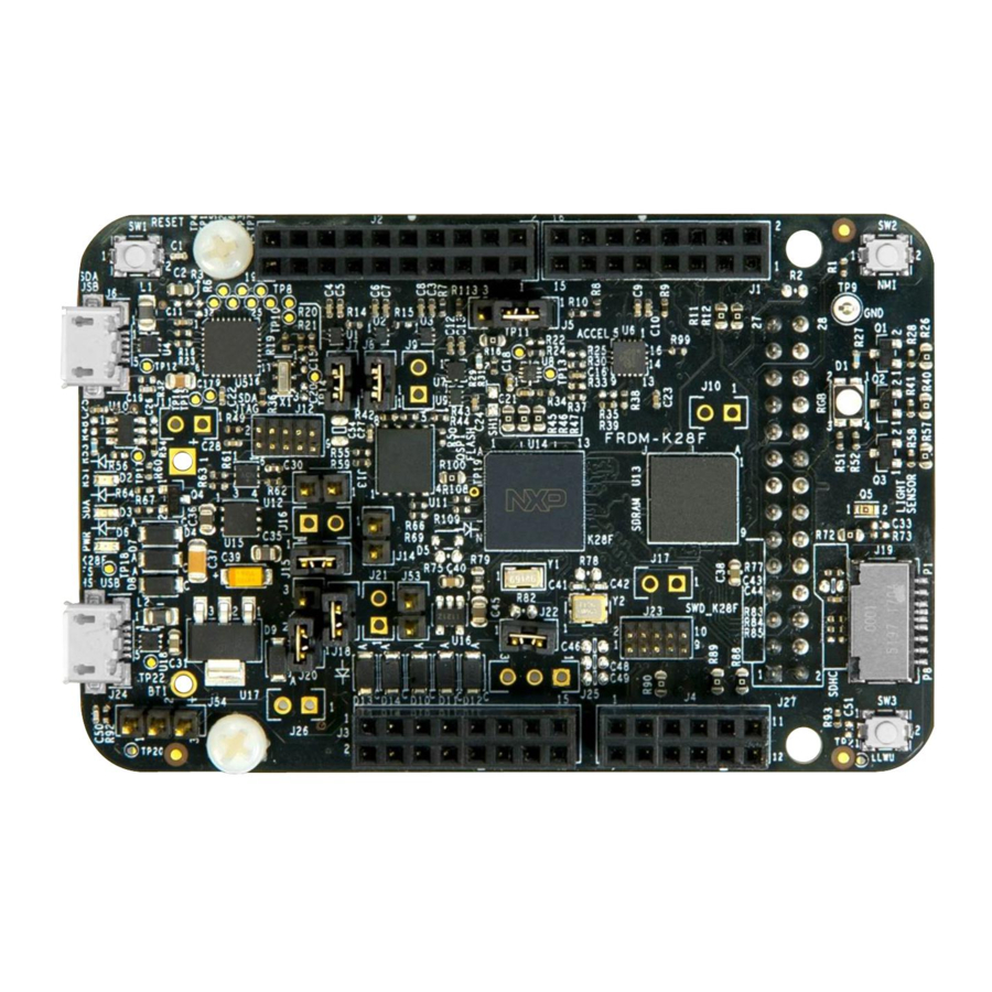
Page 2: Frdm-K28F Hardware Overview
— Virtual serial port interface. — Open-source CMSIS-DAP software project. Figure 1 shows the block diagram of the FRDM-K28F board. The primary components and their placement on the hardware assembly are shown in Figure Freedom Board for Kinetis K28F (FRDM-K28F), User's Guide, Rev. 0, 04/2017 NXP Semiconductors Arrow.com. - Page 3 FRDM-K28F hardware overview Figure 1. FRDM-K28F block diagram Freedom Board for Kinetis K28F (FRDM-K28F), User's Guide, Rev. 0, 04/2017 NXP Semiconductors Arrow.com. Arrow.com. Arrow.com. Downloaded from Downloaded from Downloaded from...
-
Page 4: Frdm-K28F Hardware Description
3.1. Power supply There are multiple power supply options on the FRDM-K28F board. It can be powered from either of the USB connectors, the VIN pin on the I/O header, or an off-board 1.71 V–3.6 V supply from the 3.3 V pin on the I/O header. - Page 5 OpenSDA v2.2 USB. However, a protection circuitry is provided to enable multiple sources to be powered at once. By default, the FRDM-K28F VDD_CORE = 1.2 V is operating in the RUN mode. To operate in the HSRUN mode, supply 1.33 V–1.47 V externally.
- Page 6 FRDM-K28F hardware description Figure 3. Power supply schematic Freedom Board for Kinetis K28F (FRDM-K28F), User's Guide, Rev. 0, 04/2017 NXP Semiconductors Arrow.com. Arrow.com. Arrow.com. Arrow.com. Arrow.com. Arrow.com. Downloaded from Downloaded from Downloaded from Downloaded from Downloaded from Downloaded from...
-
Page 7: Serial And Debug Adapter Version 2 (Opensda V2.2)
USB controller. OpenSDA v2.2 is pre-loaded with the CMSIS-DAP bootloader (an open- source MSD bootloader), and the DAP-Link interface firmware which provides the MSD flash Freedom Board for Kinetis K28F (FRDM-K28F), User's Guide, Rev. 0, 04/2017 NXP Semiconductors Arrow.com. - Page 8 J23 pin 4. This disconnects the SWD_CLK pin from the K28F so that it does not interfere with the communication to an off-board MCU connected to J17. Freedom Board for Kinetis K28F (FRDM-K28F), User's Guide, Rev. 0, 04/2017 NXP Semiconductors Arrow.com.
-
Page 9: Mcu
K28 MCU. 4. MCU FRDM-K28F features the MK28FN2M0VMI15 MCU. This 150 MHz MCU is a part of the Kinetis K2x family and it is implemented in the 169 MAPBGA and 210 WLCSP (K28 only) packages. The FRDM-K28F board also supports the K27 and K28 MCUs. The following table describes some of the features of the MK28FN2M0VMI15 MCU that is populated on this board. -
Page 10: Clocking
12 MHz crystal, which is configured to operate in the low-power mode, so the feedback resistor (R78) is not needed. The 12 MHz reference clock is suitable for both the audio codec and the HS USB features. Freedom Board for Kinetis K28F (FRDM-K28F), User's Guide, Rev. 0, 04/2017 NXP Semiconductors Arrow.com. -
Page 11: Universal Serial Bus (Usb)
USB module with the on-the-go/host/device capability and a built-in transceiver. The FRDM-K28F board routes the USB D+ and D signals from the MK28FN2M0VMI15 MCU to the high-speed analog switch (NXP NX3DV42), selecting between the HS and FS USB signals to the on-board micro USB connector (J24). -
Page 12: Vbat
Figure 8. K28F USB port When the FRDM-K28F board operates in the USB host mode, J13 must be shunted to supply 5 V to VBUS (J24 pin 1). The 5 V source can be the OpenSDA v2.2 USB port (J6) or the optional 5 V regulator populated at J25 and supplied by P5-9V_VIN at pin 16 of the J3 connector. -
Page 13: Accelerometer And Magnetometer
0x1C (pull-up on SA1 and pull-down on SA0). Table 4. Accelerometer and magnetometer signal connection FXOS8700Q K28F connection PTC29/ I2C3_SCL PTC28/ I2C3_SDA INT1 PTC26 PTC27 Freedom Board for Kinetis K28F (FRDM-K28F), User's Guide, Rev. 0, 04/2017 NXP Semiconductors Arrow.com. Arrow.com. Arrow.com. Arrow.com. Arrow.com. Arrow.com. Arrow.com. -
Page 14: Rgb Led
Table 5. LED signal connection RGB LED K28F connection PTE6 GREEN PTE7 BLUE PTE8 Figure 12. Accelerometer and magnetometer Freedom Board for Kinetis K28F (FRDM-K28F), User's Guide, Rev. 0, 04/2017 NXP Semiconductors Arrow.com. Arrow.com. Arrow.com. Arrow.com. Arrow.com. Arrow.com. Arrow.com. Arrow.com. -
Page 15: Serial Port
13. Secure Digital (SD) card A micro SD card slot is available on the FRDM-K28F board. It is connected to the SD Host Controller (SDHC) signals of the MCU. This slot accepts micro SD memory cards. The SD card detect pin is an open switch that shorts with VDD when a card is inserted. -
Page 16: Flexio Socket
There is a 28-pin header with 20 FlexIO signals connected on the bottom of the board. It is compatible with the MikroElektronica TFT Proto 5” capacitive touch display. Figure 14. Accelerometer and magnetometer Freedom Board for Kinetis K28F (FRDM-K28F), User's Guide, Rev. 0, 04/2017 NXP Semiconductors Arrow.com. -
Page 17: Reset
Figure 15. Reset circuit 16. Push-button switches Two push-buttons (SW2 and SW3) are available on the FRDM-K28F board. SW2 is connected to PTA4 and SW3 is connected to PTD0. Besides the general-purpose input/output functions, SW2 can be also used as a Low-Leakage Wakeup (LLWU) source. -
Page 18: Visible Light Sensor
Visible light sensor Figure 16. Push-button switches 17. Visible light sensor FRDM-K28F has an on-board visible light sensor (Q5) which is connected to ADC0_SE16. Figure 17. Visible light sensor Freedom Board for Kinetis K28F (FRDM-K28F), User's Guide, Rev. 0, 04/2017 NXP Semiconductors Arrow.com. -
Page 19: Debug
The debug interface on the MK28FN2M0VMI15 MCU is the Serial Wire Debug (SWD) port with the trace output capability. There are two debug interfaces on FRDM-K28F: the on-board OpenSDA v2.2 circuit (J12) and the K28F direct SWD connection via the 10-pin header (J23). To use an external debugger (such as J-Link on J23), you may need to disconnect the OpenSDA v2.2 SWD circuit from the... -
Page 20: Arduino Compatibility
Jumper table 20. Arduino compatibility The I/O headers on the FRDM-K28F board are compatible with the peripheral boards (known as shields) that connect to the Arduino and Arduino-compatible MCU boards. The outer rows of pins (the even numbered pins) on the headers share the mechanical spacing and placement with the I/O headers on the Arduino Revision 3 (R3) standard. -
Page 21: References
The following reference is available at www.nxp.com/kboot: • Kinetis Flashloader 23. Revision history Table 9. Revision history Revision number Date Substantive changes 04/2017 Initial release Freedom Board for Kinetis K28F (FRDM-K28F), User's Guide, Rev. 0, 04/2017 NXP Semiconductors Arrow.com. Arrow.com. Arrow.com. Arrow.com. Arrow.com. Arrow.com. Arrow.com. - Page 22 Information in this document is provided solely to enable system and software How to Reach Us: implementers to use NXP products. There are no express or implied copyright licenses Home Page: granted hereunder to design or fabricate any integrated circuits based on the nxp.com information in this document.
Need help?
Do you have a question about the FRDM-K28F and is the answer not in the manual?
Questions and answers