
Subscribe to Our Youtube Channel
Related Manuals for Baudcom BD3000


Summary of Contents for Baudcom BD3000
- Page 1 SHANGHAI BAUDCOM COMMUNICATION DEVICE CO.,LTD BD3000 Optical Time Domain Reflectometer USER’S GUIDE...
- Page 2 The contents of this document are subject to change without notice. If you have any questions, please call the supplier, we will be happy to provide you with the best quality service! Website: www.baudcom.com.cn Email: info@baudcom.cn Tel: +86-21-37709251...
-
Page 3: Table Of Contents
2.1 OTDR Basic Knowledge Introduction∙∙∙∙∙∙∙∙∙∙∙∙∙∙∙∙∙∙∙∙∙∙∙∙∙∙∙∙∙∙∙∙∙∙∙∙∙∙∙∙∙∙∙∙∙∙∙∙∙∙∙∙∙∙∙∙∙∙∙∙∙∙∙∙∙∙∙∙∙∙∙∙∙∙∙15 2.2 OTDR Test Event Type Introduction∙∙∙∙∙∙∙∙∙∙∙∙∙∙∙∙∙∙∙∙∙∙∙∙∙∙∙∙∙∙∙∙∙∙∙∙∙∙∙∙∙∙∙∙∙∙∙∙∙∙∙∙∙∙∙∙∙∙∙∙∙∙∙∙∙∙∙∙∙∙∙∙∙∙∙∙∙17 2.3 OTDR Dynamic Range∙∙∙∙∙∙∙∙∙∙∙∙∙∙∙∙∙∙∙∙∙∙∙∙∙∙∙∙∙∙∙∙∙∙∙∙∙∙∙∙∙∙∙∙∙∙∙∙∙∙∙∙∙∙∙∙∙∙∙∙∙∙∙∙∙∙∙∙∙∙∙∙∙∙∙∙∙∙∙∙∙∙∙∙∙∙∙∙∙∙∙∙∙∙∙∙∙∙22 2.4 OTDR Dead Zone ∙∙∙∙∙∙∙∙∙∙∙∙∙∙∙∙∙∙∙∙∙∙∙∙∙∙∙∙∙∙∙∙∙∙∙∙∙∙∙∙∙∙∙∙∙∙∙∙∙∙∙∙∙∙∙∙∙∙∙∙∙∙∙∙∙∙∙∙∙∙∙∙∙∙∙∙∙∙∙∙∙∙∙∙∙∙∙∙∙∙∙∙∙∙∙∙∙∙∙∙∙∙∙∙∙22 Chapter 3 The Basic Operation and Usage of this Series OTDR ∙∙∙∙∙∙∙∙∙∙∙∙∙∙∙∙∙∙∙∙∙∙∙∙∙∙∙∙∙∙∙∙∙∙∙∙∙∙∙∙∙∙∙∙∙∙∙∙24 3.1 Main Operating Window ∙∙∙∙∙∙∙∙∙∙∙∙∙∙∙∙∙∙∙∙∙∙∙∙∙∙∙∙∙∙∙∙∙∙∙∙∙∙∙∙∙∙∙∙∙∙∙∙∙∙∙∙∙∙∙∙∙∙∙∙∙∙∙∙∙∙∙∙∙∙∙∙∙∙∙∙∙∙∙∙∙∙∙∙∙∙∙∙∙∙∙∙∙∙25 Website: www.baudcom.com.cn Email: info@baudcom.cn Tel: +86-21-37709251... - Page 4 3.10 Manual Measurement of Average Loss Between Two Points in an Optical Fiber Link∙∙∙∙∙∙∙∙∙∙∙∙∙∙∙∙∙∙∙∙∙∙∙∙∙∙∙∙∙∙∙∙∙∙∙∙∙∙∙∙∙∙∙∙∙∙∙∙∙∙∙∙∙∙∙∙∙∙∙∙∙∙∙∙∙∙∙∙∙∙∙∙∙∙∙∙∙∙∙∙∙∙∙∙∙∙∙∙∙∙∙∙∙∙∙∙∙∙∙∙∙∙∙∙∙∙∙∙∙∙∙∙∙∙∙∙∙∙∙∙∙∙∙∙∙∙∙51 3.11 Manual Measurement of the Loss of Connection Points and Fusion Contacts in Optical Fiber Links∙∙∙∙∙∙∙∙∙∙∙∙∙∙∙∙∙∙∙∙∙∙∙∙∙∙∙∙∙∙∙∙∙∙∙∙∙∙∙∙∙∙∙∙∙∙∙∙∙∙∙∙∙∙∙∙∙∙∙∙∙∙∙∙∙∙∙∙∙∙∙∙∙∙∙∙∙∙∙∙∙∙∙∙∙∙∙∙∙∙∙∙∙∙∙∙∙∙∙∙∙∙∙∙∙∙∙∙∙∙∙∙∙∙∙∙52 3.12 Measure Echo Loss Manually ∙∙∙∙∙∙∙∙∙∙∙∙∙∙∙∙∙∙∙∙∙∙∙∙∙∙∙∙∙∙∙∙∙∙∙∙∙∙∙∙∙∙∙∙∙∙∙∙∙∙∙∙∙∙∙∙∙∙∙∙∙∙∙∙∙∙∙∙∙∙∙∙∙∙∙∙∙∙∙∙∙∙∙∙54 Website: www.baudcom.com.cn Email: info@baudcom.cn Tel: +86-21-37709251...
- Page 5 Chapter 7 Instrument Maintenance and Troubleshooting∙∙∙∙∙∙∙∙∙∙∙∙∙∙∙∙∙∙∙∙∙∙∙∙∙∙∙∙∙∙∙∙∙∙∙∙∙∙∙∙∙∙∙∙∙∙∙∙∙∙∙∙∙∙∙∙∙72 7.1 Daily Use and Maintenance of Instrument ∙∙∙∙∙∙∙∙∙∙∙∙∙∙∙∙∙∙∙∙∙∙∙∙∙∙∙∙∙∙∙∙∙∙∙∙∙∙∙∙∙∙∙∙∙∙∙∙∙∙∙∙∙∙∙∙∙∙∙∙∙∙∙∙∙72 7.2 Fault and Treatment Method∙∙∙∙∙∙∙∙∙∙∙∙∙∙∙∙∙∙∙∙∙∙∙∙∙∙∙∙∙∙∙∙∙∙∙∙∙∙∙∙∙∙∙∙∙∙∙∙∙∙∙∙∙∙∙∙∙∙∙∙∙∙∙∙∙∙∙∙∙∙∙∙∙∙∙∙∙∙∙∙∙∙∙∙∙∙∙75 Chapter 8 Technical Parameters and Ordering Information∙∙∙∙∙∙∙∙∙∙∙∙∙∙∙∙∙∙∙∙∙∙∙∙∙∙∙∙∙∙∙∙∙∙∙∙∙∙∙∙∙∙∙∙∙∙∙∙∙∙∙∙∙∙80 8.1 Technical Parameters of OTDR ∙∙∙∙∙∙∙∙∙∙∙∙∙∙∙∙∙∙∙∙∙∙∙∙∙∙∙∙∙∙∙∙∙∙∙∙∙∙∙∙∙∙∙∙∙∙∙∙∙∙∙∙∙∙∙∙∙∙∙∙∙∙∙∙∙∙∙∙∙∙∙∙∙∙∙∙∙∙∙∙∙∙80 8.2 Order Information ∙∙∙∙∙∙∙∙∙∙∙∙∙∙∙∙∙∙∙∙∙∙∙∙∙∙∙∙∙∙∙∙∙∙∙∙∙∙∙∙∙∙∙∙∙∙∙∙∙∙∙∙∙∙∙∙∙∙∙∙∙∙∙∙∙∙∙∙∙∙∙∙∙∙∙∙∙∙∙∙∙∙∙∙∙∙∙∙∙∙∙∙∙∙∙∙∙∙∙∙∙∙∙87 Website: www.baudcom.com.cn Email: info@baudcom.cn Tel: +86-21-37709251...
-
Page 6: Chapter 1 Summary∙∙∙∙∙∙∙∙∙∙∙∙∙∙∙∙∙∙∙∙∙∙∙∙∙∙∙∙∙∙∙∙∙∙∙∙∙∙∙∙∙∙∙∙∙∙∙∙∙∙∙∙∙∙∙∙∙∙∙∙∙∙∙∙∙∙∙∙∙∙∙∙∙∙∙∙∙∙∙∙∙∙∙∙∙∙∙∙∙∙∙∙∙∙∙∙∙∙∙∙∙∙∙∙∙∙∙∙∙∙∙∙∙∙∙∙∙∙∙∙6
In the product packaging, along with the instrument, should also be equipped with a power cord, adapter, analysis software and user manuals, etc.. After you receive the instrument, please check the integrity of the packaging of the equipment for the first time. If you find that the Website: www.baudcom.com.cn Email: info@baudcom.cn Tel: +86-21-37709251... - Page 7 Form 1-1 Basic Composition of OTDR ITEM NAME QUANTITY MASTER BD3000 OTDR Power Cord Power Adapter User’s Guide Accessory U Disk(Including simulation analysis software) Options Touch Pen...
- Page 8 1.2 Summary The BD3000 series of optical time domain reflectometer (OTDR) is a new generation of intelligent optical fiber measuring instrument designed for the testing of optical fiber communication system. This product is mainly used to measure various types of optical fiber, optical cable length, loss, and other parameters of the quality of the connection;...
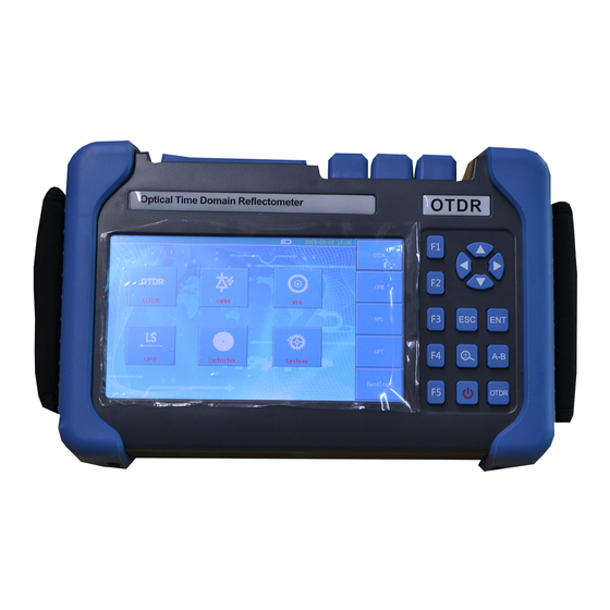
- Page 9 In addition to the OTDR function, the instrument can also be equipped with optical power meter, light source, visual fault location (VFL) and the end detection function. Figure 1-1 BD3000 Main Menu Website: www.baudcom.com.cn Email: info@baudcom.cn...
-
Page 10: 1.3 Attentions
1.3.2 Internal Battery Internal lithium battery. In order to give full play to the performance of the battery, in the beginning of the use of this instrument, please use the internal battery power, the battery power Website: www.baudcom.com.cn Email: info@baudcom.cn Tel: +86-21-37709251... - Page 11 In the use of this instrument, please pay attention to avoid the eyes of laser output, but also not in the test, open end fiber; when the instrument after use, please cover the light output of the dust cap. Website: www.baudcom.com.cn Email: info@baudcom.cn Tel: +86-21-37709251...
- Page 12 3. Because of the external factors can not resist the instrument damage or performance degradation, will not be within the scope of warranty. 4. Due to improper operation of the instrument damage or performance degradation, will not be within the scope of warranty. Website: www.baudcom.com.cn Email: info@baudcom.cn Tel: +86-21-37709251...
- Page 13 Please note that when the product returns: Using polyethylene thin soft pad instrument package, with perfect protection instrument housing; Please use a hard packing box to ensure that the instrument is filled with at least 3 cm Website: www.baudcom.com.cn Email: info@baudcom.cn Tel: +86-21-37709251...
- Page 14 Fill in the product maintenance card correctly, including company name, address, contact person, telephone number, problem description and so on; Deliver the goods to your supplier in a reliable manner. Website: www.baudcom.com.cn Email: info@baudcom.cn Tel: +86-21-37709251...
-
Page 15: Chapter 2 Otdr Introduction∙∙∙∙∙∙∙∙∙∙∙∙∙∙∙∙∙∙∙∙∙∙∙∙∙∙∙∙∙∙∙∙∙∙∙∙∙∙∙∙∙∙∙∙∙∙∙∙∙∙∙∙∙∙∙∙∙∙∙∙∙∙∙∙∙∙∙∙∙∙∙∙∙∙∙∙∙∙∙∙∙∙∙∙∙∙∙∙∙∙∙∙∙∙∙∙∙∙∙∙∙∙∙15
Rayleigh scattering occurs, where a portion of the optical signal will be shot into the opposite direction along the veins are scattered back, so it is called the Rayleigh backscattering, through the observation of Website: www.baudcom.com.cn Email: info@baudcom.cn Tel: +86-21-37709251... - Page 16 Fresnel reflection signal, can be accurately located along the length of the fiber discontinuous point. The size of the reflection depends on the refractive index difference and the smoothness of the boundary surface. Website: www.baudcom.com.cn Email: info@baudcom.cn Tel: +86-21-37709251...
- Page 17 To return to the instrument, the instrument through the acceptance of the reflected signals, will detect the Website: www.baudcom.com.cn Email: info@baudcom.cn Tel: +86-21-37709251...
- Page 18 In the OTDR test curve, it is shown that the peak width and amplitude are determined by the pulse width and the reflected intensity. As shown in figure 2-1. Figure 2-1 Reflection Events Diagram Website: www.baudcom.com.cn Email: info@baudcom.cn Tel: +86-21-37709251...
- Page 19 OTDR, which can be used to detect the non reflection event parameters. Non reflection events declined as a signal energy in the test curve of OTDR, the decrease of said power loss situation. As shown in Figure 2-2. Website: www.baudcom.com.cn Email: info@baudcom.cn Tel: +86-21-37709251...
-
Page 20: Otdr Dynamic Range∙∙∙∙∙∙∙∙∙∙∙∙∙∙∙∙∙∙∙∙∙∙∙∙∙∙∙∙∙∙∙∙∙∙∙∙∙∙∙∙∙∙∙∙∙∙∙∙∙∙∙∙∙∙∙∙∙∙∙∙∙∙∙∙∙∙∙∙∙∙∙∙∙∙∙∙∙∙∙∙∙∙∙∙∙∙∙∙∙∙∙∙∙∙∙∙∙∙22
Dynamic range is an important parameter of optical time domain reflectometer (dB). This parameter is expressed as the maximum optical loss of OTDR that can be analyzed from the backscatter level of the instrument output port to a specific noise level. In the practical use of Website: www.baudcom.com.cn Email: info@baudcom.cn Tel: +86-21-37709251... - Page 21 The maximum test distance of OTDR is different in different applications, because the loss of the measured link is different. Connectors, welding and splitter are also factors that reduce the OTDR test length. Website: www.baudcom.com.cn Email: info@baudcom.cn Tel: +86-21-37709251...
-
Page 22: Otdr Dead Zone ∙∙∙∙∙∙∙∙∙∙∙∙∙∙∙∙∙∙∙∙∙∙∙∙∙∙∙∙∙∙∙∙∙∙∙∙∙∙∙∙∙∙∙∙∙∙∙∙∙∙∙∙∙∙∙∙∙∙∙∙∙∙∙∙∙∙∙∙∙∙∙∙∙∙∙∙∙∙∙∙∙∙∙∙∙∙∙∙∙∙∙∙∙∙∙∙∙∙∙∙∙∙∙∙∙22
OTDR dead zone is divided into event blind area and attenuation blind area. Two kinds of blind areas are generated by the Fresnel reflection, in order to reflect the change in the power of Website: www.baudcom.com.cn Email: info@baudcom.cn Tel: +86-21-37709251... - Page 23 Fresnel reflection signal。 ATT Dead Zone: Refers to the OTDR signal detected from the Fresnel reflection to the shortest distance to the normal test of Rayleigh backscattering signal. Website: www.baudcom.com.cn Email: info@baudcom.cn Tel: +86-21-37709251...
-
Page 24: Chapter 3 The Basic Operation And Usage Of This Series Otdr ∙∙∙∙∙∙∙∙∙∙∙∙∙∙∙∙∙∙∙∙∙∙∙∙∙∙∙∙∙∙∙∙∙∙∙∙∙∙∙∙∙∙∙∙∙∙∙∙24
3-1. The main operating window contains all of the 5 OTDR main operating menu, each menu bar contains a different sub window, through the operation button will start a different sub window to achieve the corresponding functions. (detailed description of Website: www.baudcom.com.cn Email: info@baudcom.cn Tel: +86-21-37709251... - Page 25 3.1 This series of OTDR main operating window Figure 3-1 Main Operating Interface Website: www.baudcom.com.cn Email: info@baudcom.cn Tel: +86-21-37709251...
- Page 26 Figure 3-1, at this time the instrument set parameters, file information. After testing the curve, the display window is displayed as an event analysis list for the entire link when the curve is analyzed. Website: www.baudcom.com.cn Email: info@baudcom.cn Tel: +86-21-37709251...
-
Page 27: The Menu Structure And Function Of Otdr ∙∙∙∙∙∙∙∙∙∙∙∙∙∙∙∙∙∙∙∙∙∙∙∙∙∙∙∙∙∙∙∙∙∙∙∙∙∙∙∙∙∙∙∙∙∙∙∙∙∙∙∙∙∙∙∙∙∙∙∙∙∙∙∙∙27
The utility model has the advantages that the operation is more convenient, and the user's frequent movement of the cursor is omitted Process. Website: www.baudcom.com.cn Email: info@baudcom.cn Tel: +86-21-37709251... -
Page 28: Key Function Introduction Of Otdr ∙∙∙∙∙∙∙∙∙∙∙∙∙∙∙∙∙∙∙∙∙∙∙∙∙∙∙∙∙∙∙∙∙∙∙∙∙∙∙∙∙∙∙∙∙∙∙∙∙∙∙∙∙∙∙∙∙∙∙∙∙∙∙∙∙∙∙∙∙∙∙∙∙∙∙∙28
3.3 Key Function Introduction of OTDR OTDR Figure 3-2 Key Introduction The key function of each button is under: Website: www.baudcom.com.cn Email: info@baudcom.cn Tel: +86-21-37709251... - Page 29 :OTDR Test Button, Press this button to open or stop the test of the optical fiber or cable. :A\B Cursor toggle Button, Press this button to achieve the cursor A and cursor B switching function. :Zoom\Move Select Button, Press this button to achieve the zoom function or cursor movement function. Website: www.baudcom.com.cn Email: info@baudcom.cn Tel: +86-21-37709251...
- Page 30 :ESC Button, Press this button to exit the test or the current test function or return to the main function. :Navigation Button, Press this button can be select the function of cursor movement or zoom in or out. Website: www.baudcom.com.cn Email: info@baudcom.cn Tel: +86-21-37709251...
-
Page 31: The Setting Method Of The Parameters Of The Otdr ∙∙∙∙∙∙∙∙∙∙∙∙∙∙∙∙∙∙∙∙∙∙∙∙∙∙∙∙∙∙∙∙∙∙∙∙∙∙∙∙∙∙∙∙∙∙∙∙∙∙∙31
(all test parameters can be the interface of the instrument complete set), as shown in figure 3-3. Website: www.baudcom.com.cn Email: info@baudcom.cn Tel: +86-21-37709251... - Page 32 Fig 3-3 Parameter Setting Interface Website: www.baudcom.com.cn Email: info@baudcom.cn Tel: +86-21-37709251...
-
Page 33: Parameter Introduction And Setting Method ∙∙∙∙∙∙∙∙∙∙∙∙∙∙∙∙∙∙∙∙∙∙∙∙∙∙∙∙∙∙∙∙∙∙∙∙∙∙∙∙∙∙∙∙∙∙∙∙∙∙∙∙∙∙∙∙∙∙∙∙∙∙∙∙∙33
The range is set according to the actual length of the fiber to select the appropriate predefined range, it must be greater than the length of the measured fiber, usually set to two times the length of the measured fiber. Website: www.baudcom.com.cn Email: info@baudcom.cn Tel: +86-21-37709251... - Page 34 This series of OTDR for a variety of different length of the range, the pulse width of the test to do the corresponding streamlined processing, a great convenience to the operator's selection process. In actual operation, it is recommended to use the optional range of the maximum pulse Website: www.baudcom.com.cn Email: info@baudcom.cn Tel: +86-21-37709251...
- Page 35 The setting method:In the parameter settings interface, click on the "pulse width" menu, that is, the 5ns~20000ns option, click Select the corresponding pulse width. Test mode:Mode for selecting OTDR scan. Includes "real time testing", "average test" and "automatic test". Website: www.baudcom.com.cn Email: info@baudcom.cn Tel: +86-21-37709251...
- Page 36 Match the test conditions, without the user manually set parameters. The setting method: Under the parameter setting interface, click on the "test mode", that is, "automatic test", "real-time test", "average test" option, click Select the appropriate test mode. Website: www.baudcom.com.cn Email: info@baudcom.cn Tel: +86-21-37709251...
- Page 37 [OK] and exit window. Loss display: The type used to select the OTDR test event. "Average loss", "Connection loss" Website: www.baudcom.com.cn Email: info@baudcom.cn Tel: +86-21-37709251...
- Page 38 "average loss", "connection loss" and "return loss", click Select the corresponding loss. Group refractive index:The refractive index of the fiber affects the transmission speed of the laser in the optical fiber, so the accuracy of the refractive index is directly affected by the Website: www.baudcom.com.cn Email: info@baudcom.cn Tel: +86-21-37709251...
- Page 39 The refractive index of optical fiber is provided by optical fiber manufacturers. The setting method:In the parameter settings interface, click on “group refractive index”, pop index input interface, enter the refractive index of the optical fiber is measured, click [OK] exit window. Website: www.baudcom.com.cn Email: info@baudcom.cn Tel: +86-21-37709251...
- Page 40 The setting method:In the parameter settings interface, click on the corresponding threshold menu to pop up the threshold input interface, click on the input threshold “OK” to exit window. Website: www.baudcom.com.cn Email: info@baudcom.cn Tel: +86-21-37709251...
-
Page 41: Introduction Of Loss Test ∙∙∙∙∙∙∙∙∙∙∙∙∙∙∙∙∙∙∙∙∙∙∙∙∙∙∙∙∙∙∙∙∙∙∙∙∙∙∙∙∙∙∙∙∙∙∙∙∙∙∙∙∙∙∙∙∙∙∙∙∙∙∙∙∙∙∙∙∙∙∙∙∙∙∙∙∙∙∙∙∙∙∙∙∙∙∙∙∙∙∙∙∙∙41
In the average loss test mode, OTDR will test the distance between the cursor A and B, the loss between the cursor A and B, the average loss between the cursor A and B. Click the panel Website: www.baudcom.com.cn Email: info@baudcom.cn... - Page 42 A or B cursor position,The utility model can satisfy the customer to observe the detailed loss of any distance between the optical fiber links. As shown in figure 3-4. Fig.3-4 Average Loss Test Website: www.baudcom.com.cn Email: info@baudcom.cn Tel: +86-21-37709251...
- Page 43 A in measured the positions of left sides and close to the incident, placed cursor B in measured the positions of right sides and close to the incident,. As shown in figure 3-5. Website: www.baudcom.com.cn Email: info@baudcom.cn Tel: +86-21-37709251...
- Page 44 Fig.3-5 Connection Loss Test Website: www.baudcom.com.cn Email: info@baudcom.cn Tel: +86-21-37709251...
- Page 45 Place the cursor B at the top position of the reflection event. The return loss can be read by the return loss. As show in figure 3-6. Website: www.baudcom.com.cn Email: info@baudcom.cn Tel: +86-21-37709251...
-
Page 46: Curve Analysis And Event List ∙∙∙∙∙∙∙∙∙∙∙∙∙∙∙∙∙∙∙∙∙∙∙∙∙∙∙∙∙∙∙∙∙∙∙∙∙∙∙∙∙∙∙∙∙∙∙∙∙∙∙∙∙∙∙∙∙∙∙∙∙∙∙∙∙∙∙∙∙∙∙∙∙∙∙∙∙∙∙∙∙∙∙∙∙46
3.7 Curve Analysis and Event List After the OTDR test end and gets the test curve. Click “analysis” menu or click button, OTDR will analyze the obtained curves, According to the threshold of the event, the event points Website: www.baudcom.com.cn Email: info@baudcom.cn Tel: +86-21-37709251... - Page 47 Reflection event: This event is a reflection event. usually caused by an active connector in an optical fiber link. Fiber Splitter:Usually caused by fiber splitter in an optical fiber link. Website: www.baudcom.com.cn Email: info@baudcom.cn Tel: +86-21-37709251...
- Page 48 Return loss:The return loss of current event point. Link loss: The total loss of the link from the start point to the current point in the link. Reflection loss: Reflection loss of reflection events caused by active connections in a link。 Website: www.baudcom.com.cn Email: info@baudcom.cn Tel: +86-21-37709251...
-
Page 49: Move Or Switch Cursor∙∙∙∙∙∙∙∙∙∙∙∙∙∙∙∙∙∙∙∙∙∙∙∙∙∙∙∙∙∙∙∙∙∙∙∙∙∙∙∙∙∙∙∙∙∙∙∙∙∙∙∙∙∙∙∙∙∙∙∙∙∙∙∙∙∙∙∙∙∙∙∙∙∙∙∙∙∙∙∙∙∙∙∙∙∙∙∙∙∙∙∙∙∙∙∙∙49
Fig.3-7 Analysis Result 3.8 Move or Switch Cursor Website: www.baudcom.com.cn Email: info@baudcom.cn Tel: +86-21-37709251... -
Page 50: Zoom Or Move The Curve ∙∙∙∙∙∙∙∙∙∙∙∙∙∙∙∙∙∙∙∙∙∙∙∙∙∙∙∙∙∙∙∙∙∙∙∙∙∙∙∙∙∙∙∙∙∙∙∙∙∙∙∙∙∙∙∙∙∙∙∙∙∙∙∙∙∙∙∙∙∙∙∙∙∙∙∙∙∙∙∙∙∙∙∙∙∙∙∙∙∙∙∙∙50
, as show in figure(1), 、 、 Press Navigation key can move the curve at Horizontal or vertical translation. Press the horizontal zoom function button in the curve menu Website: www.baudcom.com.cn Email: info@baudcom.cn Tel: +86-21-37709251... -
Page 51: Manual Measurement Of Average Loss Between Two Points In An Optical Fiber
Place the cursor A and B at any two points on the linear region of the measured fiber segment. ● The average value of the average loss displayed on the operating window is the average loss of the fiber segment to be tested. As show in figure 3-8. Website: www.baudcom.com.cn Email: info@baudcom.cn Tel: +86-21-37709251... - Page 52 Fig.3-8 Average Loss Measurement 3.11 Manual measurement of the loss of connection points and fusion contacts in optical fiber links Manually test the connection loss of a connection point: Website: www.baudcom.com.cn Email: info@baudcom.cn Tel: +86-21-37709251...
- Page 53 The small cursor at the end of the cursor B is placed at the end of the segment of the optical fiber before the event of the connection. ● The connection loss of the measured connection point is displayed on the operation window. Website: www.baudcom.com.cn Email: info@baudcom.cn Tel: +86-21-37709251...
-
Page 54: Measure Echo Loss Manually ∙∙∙∙∙∙∙∙∙∙∙∙∙∙∙∙∙∙∙∙∙∙∙∙∙∙∙∙∙∙∙∙∙∙∙∙∙∙∙∙∙∙∙∙∙∙∙∙∙∙∙∙∙∙∙∙∙∙∙∙∙∙∙∙∙∙∙∙∙∙∙∙∙∙∙∙∙∙∙∙∙∙∙∙54
If you want to manually test the return loss of a connection point, the steps are as follows: In the OTDR settings window, set the test item to echo loss test. At this time, there will be 2 cursors, cursor A and cursor B. Website: www.baudcom.com.cn Email: info@baudcom.cn Tel: +86-21-37709251... - Page 55 Mark point B is located at the top of the measured reflection event. At this time, the value of the return loss displayed on the operation window is the return loss of the measured connection point. As shown in Figure 3-10. Website: www.baudcom.com.cn Email: info@baudcom.cn Tel: +86-21-37709251...
-
Page 56: File Management Class ∙∙∙∙∙∙∙∙∙∙∙∙∙∙∙∙∙∙∙∙∙∙∙∙∙∙∙∙∙∙∙∙∙∙∙∙∙∙∙∙∙∙∙∙∙∙∙∙∙∙∙∙∙∙∙∙∙∙∙∙∙∙∙∙∙∙∙∙∙∙∙∙∙∙∙∙∙∙∙∙∙∙∙∙∙∙∙∙∙∙∙∙56
The following is the introduction of this series of OTDR file management operations, including file read, save, copy, delete, etc.. When measuring, the measurement curve can be saved. The contents of the preservation curve include: the curve and the curve of the relevant Website: www.baudcom.com.cn Email: info@baudcom.cn Tel: +86-21-37709251... - Page 57 In the test of the main interface, click on the [file] - [read], pop-up file read interface, click on the [file path], the path of the file list, select the corresponding file, click [read], as shown in figure 3-11. Fig.3-11 File Read 3.13.2 File Save Website: www.baudcom.com.cn Email: info@baudcom.cn Tel: +86-21-37709251...
- Page 58 In the test main interface, click [file] - [save], pop-up file save interface, enter the file name, select the file to save the path and format, click [OK], as shown in Figure 3-12. Fig.3-12 File Save 3.13.3 File Copy Website: www.baudcom.com.cn Email: info@baudcom.cn Tel: +86-21-37709251...
- Page 59 In the test main interface, click [file] - [save], pop-up file copy interface, you can choose to copy the file to the U disk memory. Fig.3-13 File Copy 3.13.4 File Deletion Website: www.baudcom.com.cn Email: info@baudcom.cn Tel: +86-21-37709251...
- Page 60 In the test main interface, click [file] - [delete], pop-up file delete interface, select the name of the file you want to delete, click Delete to delete the appropriate file. Fig.3-14 File Deletion 3.14.5 System Time, Language Settings, System Upgrades and View System Website: www.baudcom.com.cn Email: info@baudcom.cn Tel: +86-21-37709251...
- Page 61 [settings/upgrade] to enter the system information settings window. In the system [settings/upgrade] interface, the system time, the system language settings, the touch screen can be calibrated, the software can be upgraded. As shown in Figure 3-15. Fig.3-15 System Settings/Upgrade Interface Website: www.baudcom.com.cn Email: info@baudcom.cn Tel: +86-21-37709251...
- Page 62 Fig.3-16 System Settings/Upgrade Interface Note: the [system time], [language] and [Brightness]option in the page can be set up by the user, the rest is the inherent parameters of the system. Website: www.baudcom.com.cn Email: info@baudcom.cn Tel: +86-21-37709251...
- Page 63 Guide to the rapid operation of this test instrument. By the navigation keys on the left and right buttons to turn pages. Press the return key to exit the window. As shown in Figure 3-17. Website: www.baudcom.com.cn Email: info@baudcom.cn Tel: +86-21-37709251...
- Page 64 Fig.3-17 Help Information Interface Website: www.baudcom.com.cn Email: info@baudcom.cn Tel: +86-21-37709251...
-
Page 65: Chapter 4 Basic Operation And Use Method Of Optical Power Meter∙∙∙∙∙∙∙∙∙∙∙∙∙∙∙∙∙∙∙∙∙∙∙∙∙∙∙∙∙∙∙∙∙∙∙∙∙∙65
Figure 4-1. Fig.4-1 Optical power meter test interface The menu button function and operating instructions are as follows: Website: www.baudcom.com.cn Email: info@baudcom.cn Tel: +86-21-37709251... - Page 66 [settings]: enter the settings interface, changing the wavelength, unit, the average number of times, the range of parameters. As shown in figure 4-2. Fig.4-2 Power meter setting interface [Wavelength]Wavelength switching can be achieved, selectable wavelengths of 850nm, Website: www.baudcom.com.cn Email: info@baudcom.cn Tel: +86-21-37709251...
- Page 67 [zero]: the implementation of the adjustment of power meter zero point. [reference] relative measurement of optical power mode, dB mode. [return]: exit the Optical power interface, return to the main operating interface. Website: www.baudcom.com.cn Email: info@baudcom.cn Tel: +86-21-37709251...
-
Page 68: Chapter 5 Introduce Of The Function Of Face Detection ∙∙∙∙∙∙∙∙∙∙∙∙∙∙∙∙∙∙∙∙∙∙∙∙∙∙∙∙∙∙∙∙∙∙∙∙∙∙∙∙∙∙∙∙∙∙∙∙∙∙∙∙∙∙∙∙∙∙69
, or click on the [end detection] module, into the end of the test interface. Detect the optical fiber connector access to the end detector to see whether the end surface is clean. As shown in figure 5-1. Fig.5-1 End detection interface Website: www.baudcom.com.cn Email: info@baudcom.cn Tel: +86-21-37709251... -
Page 69: Chapter 6 Visual Fault Location(Vfl)∙∙∙∙∙∙∙∙∙∙∙∙∙∙∙∙∙∙∙∙∙∙∙∙∙∙∙∙∙∙∙∙∙∙∙∙∙∙∙∙∙∙∙∙∙∙∙∙∙∙∙∙∙∙∙∙∙∙∙∙∙∙∙∙∙∙∙∙∙∙∙∙∙∙∙∙∙∙∙∙70
Chapter 6 Visual Fault Location(VFL) Click on the figure 6-1 [VFL], will enter the visual fault locator operating interface, as shown in Figure 6-1。 Fig.6-1 VFL Operation interface Website: www.baudcom.com.cn Email: info@baudcom.cn Tel: +86-21-37709251... - Page 70 VFL operating instructions are as follows: Click [VFL], visual fault location mode for 1Hz modulation light output; Click [VFL], visual fault location mode continuous light output; Click [VFL], visual fault location function off. Website: www.baudcom.com.cn Email: info@baudcom.cn Tel: +86-21-37709251...
-
Page 71: Chapter 7 Instrument Maintenance And Troubleshooting∙∙∙∙∙∙∙∙∙∙∙∙∙∙∙∙∙∙∙∙∙∙∙∙∙∙∙∙∙∙∙∙∙∙∙∙∙∙∙∙∙∙∙∙∙∙∙∙∙∙∙∙∙∙∙∙∙72
Unscrew the output interface, use a special paper towel or cotton swab moistened with alcohol to wipe the connecting end face. At the same time, in the normal use of the instrument, after the completion of the dust cap Website: www.baudcom.com.cn Email: info@baudcom.cn Tel: +86-21-37709251... - Page 72 When the instrument is not used for a long time, please charge the battery on a regular basis, it is recommended that every 2 to 3 months for the battery charging operation to ensure the best performance of the battery. Website: www.baudcom.com.cn Email: info@baudcom.cn Tel: +86-21-37709251...
- Page 73 LCD screen, otherwise it may cause damage to the LCD screen. 7.1.4 Instrument Calibration In the normal use of the instrument, it is recommended that the optical time domain reflectometer calibration every two years. Please contact the instrument supplier for specific calibration. Website: www.baudcom.com.cn Email: info@baudcom.cn Tel: +86-21-37709251...
-
Page 74: Fault And Treatment Method∙∙∙∙∙∙∙∙∙∙∙∙∙∙∙∙∙∙∙∙∙∙∙∙∙∙∙∙∙∙∙∙∙∙∙∙∙∙∙∙∙∙∙∙∙∙∙∙∙∙∙∙∙∙∙∙∙∙∙∙∙∙∙∙∙∙∙∙∙∙∙∙∙∙∙∙∙∙∙∙∙∙∙∙∙∙∙75
The instrument is placed in Use the environment to meet the environment of 0℃ ~ the charging conditions Instrument can not charge 50℃. Open the battery compartment Poor battery contact cover, check battery Website: www.baudcom.com.cn Email: info@baudcom.cn Tel: +86-21-37709251... - Page 75 The output end of the optical Clean light output face fiber is polluted Unable to measure normal curve Optical output connector Replace output connector damage Optical output connector Replace matching connector. mismatch Website: www.baudcom.com.cn Email: info@baudcom.cn Tel: +86-21-37709251...
- Page 76 Incorrect channel settings parameters The output end of the optical Slow down the test curve Clean light output face starting end reflection peak, fiber is polluted trailing phenomenon Optical output connector Replace output connector Website: www.baudcom.com.cn Email: info@baudcom.cn Tel: +86-21-37709251...
- Page 77 Poor quality of test curve. parameters. analysis Event threshold setting. Add event threshold. Instrument parameter setting Resetting appropriate Measurement of fiber length error parameters is not accurate The refractive index of optical Fiber refractive index Website: www.baudcom.com.cn Email: info@baudcom.cn Tel: +86-21-37709251...
- Page 78 The above description is only for reference, please refer to the instructions for use. In the use of the instrument, if in doubt, can contact with the instrument supplier. The instrument in use, without permission, the user must not arbitrarily disassemble, otherwise it will lose the warranty! Website: www.baudcom.com.cn Email: info@baudcom.cn Tel: +86-21-37709251...
-
Page 79: Chapter 8 Technical Parameters And Ordering Information∙∙∙∙∙∙∙∙∙∙∙∙∙∙∙∙∙∙∙∙∙∙∙∙∙∙∙∙∙∙∙∙∙∙∙∙∙∙∙∙∙∙∙∙∙∙∙∙∙∙∙∙∙∙80
8.1 Technical Parameters of OTDR Form 8-1 This series OTDR technical parameters OTDR model item Fiber type single mode multimode Central 1310nm/1550nm 850nm/1300nm wavelength ± 20nm ± 20nm Maximum 32/30 37/35 42/40 22/36 dynamic Website: www.baudcom.com.cn Email: info@baudcom.cn Tel: +86-21-37709251... - Page 80 (dB) Event Dead 1.5m 1.5m 1.5m Zone ATT dead zone Panel type 800× 480、7inch color LCD、Touch screen operation Optical FC/UPC (SC or ST) interface 2km、4km、8km、 、 500m、1km、2km、4km、8km 16km 32km Test range 16km、32km、64km、128km @850nm; 2km、4km、8km、 Website: www.baudcom.com.cn Email: info@baudcom.cn Tel: +86-21-37709251...
- Page 81 16km 、 32km 、 64km 128 、 256km ; @1300nm 5、10、30、100、 275、500、1000 @850nm; 5、10、30、50、100、275 Pulse width 500、1000、5000、10000ns 10、30、50、100、 275、500、1000、 5000 @1300nm Ranging ± (1m+ Sampling interval +0.005%× distance) accuracy Website: www.baudcom.com.cn Email: info@baudcom.cn Tel: +86-21-37709251...
- Page 82 Attenuation measurement ± 0.05 dB/dB accuracy Reflection measurement ± 4dB accuracy ≥1000 test curve Data storage Communicati on interface Visible red light source Output ≥2mW power Website: www.baudcom.com.cn Email: info@baudcom.cn Tel: +86-21-37709251...
- Page 83 Test ≥5 km distance Environmental adaptability AC/DCAdapter:AC:100V~240V(1.5A) ,50/60Hz Power DC:12V~20V(2A) supply mode Battery:7.4V,10000mAh Battery ≥ 12 hours working time Working -5℃ ~ 50℃ temperature -20℃ ~ 70℃ Preservation Website: www.baudcom.com.cn Email: info@baudcom.cn Tel: +86-21-37709251...
- Page 84 Note: 1, the ambient temperature of 23℃± 2℃, the maximum test pulse width, the average time is greater than 3 minutes 2, blind test conditions (range 500m, pulse width 10ns, channel three), reflecting optical fiber loss is larger than 45dB, the typical value; 3, low brightness, not test. Website: www.baudcom.com.cn Email: info@baudcom.cn Tel: +86-21-37709251...
- Page 85 Optical time domain reflectometer Power cord AC/DC power adapter User's Manual U disk (including simulation analysis software) Touch pen The special instruments (including backpack straps) Note: the OTDR standard interface type FC/UPC, type FC/APC optional Website: www.baudcom.com.cn Email: info@baudcom.cn Tel: +86-21-37709251...
- Page 86 Note: the above contents are subject to change without prior notice due to the need for design improvement. Website: www.baudcom.com.cn Email: info@baudcom.cn Tel: +86-21-37709251...
Need help?
Do you have a question about the BD3000 and is the answer not in the manual?
Questions and answers