GTE ADICOS HOTSPOT-1000 Operating Manual
Ir temperature detector
Hide thumbs
Also See for ADICOS HOTSPOT-1000:
- Installation operation & maintenance (36 pages) ,
- Operating manual (36 pages)

Related Manuals for GTE ADICOS HOTSPOT-1000


Summary of Contents for GTE ADICOS HOTSPOT-1000
- Page 1 HOTSPOT-1000 Operating Manual IR temperatur detector GTE Industrieelektronik GmbH | Helmholtzstr. 21, 38 – 40 41747 Viersen | Germany | +49 2162 3703-0 | info@gte.de...
- Page 2 Support hotline: +49 (0)2162 /37030 E-mail: service@adicos.de © 2018 GTE Industrieelektronik GmbH – This document and all illustrations contained herein are protected by copyright and may not be copied and pasted, modified or distributed with- out the express consent of the manufacturer!
- Page 3 The ADICOS HOTSPOT-1000 is an IR fire detector used for optical and spatially resolved fire and heat detection. It is well suited for these applications: •...
-
Page 4: Table Of Contents
Commissioning ..........22 410-2410-001 EN12 ADICOS HOTSPOT-1000... - Page 5 Measuring Range ........29 10.2 Accuracy of Standard Version ADICOS HOTSPOT-1000 ..29 10.3 Purge Air Requirements.
-
Page 6: About This Manual
(e.g. screens, internal function steps, etc.), they are shown like this: Intermediate state Warnings The following types of notes are used through this manual: Tips and recommendations This type of note provides information that is directly relevant for the further operation of the device. 410-2410-001 EN12 ADICOS HOTSPOT-1000... -
Page 7: Abbreviations
Field Device Network (fire detection bus, SIEMENS fire detection systems) Local Security Network (fire detection bus, BOSCH fire detection systems) Fire detection system Storing this Manual Store this manual near the detectors, in a place where it can easily be accessed when needed for reference. ADICOS HOTSPOT-1000 410-2410-001 EN12... -
Page 8: For Your Safety
Intended use also includes following the instructions in this manual and complying with all relevant local regulations. The ADICOS HOTSPOT-1000 may not be used for any other purpose. If the device is used in any other way, or if changes are made to the product, including in the course of installation and maintenance, the warranty claim is no longer valid. -
Page 9: Qualification Required Of Personnel
• When in doubt, consult the manufacturer! Accessories and Spare Parts WARNING! Only original spare parts and accessories provided by the manufacturer may be used! WARNING! Original spare parts and accessories may be installed only by properly trained personnel. ADICOS HOTSPOT-1000 410-2410-001 EN12... -
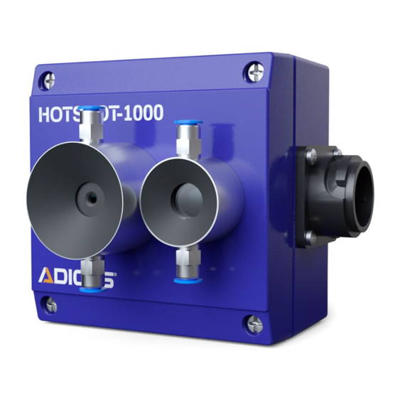
Page 10: Product Description
It is used for early and contact-free temperature and ember detection. Because of its dura- ble design, the ADICOS HOTSPOT-1000 can be used in adverse industrial environments. It is excellent for monitoring bulk goods prone to spontaneous combustion as well as conveyor systems. -
Page 11: Sensor Specification
The ADICOS HOTSPOT-1000 optics are integrated in a stainless steel tube, that prevents dust from collecting on the lens at low air flow. In order to protect the ADICOS HOTSPOT-1000 optics from getting polluted in case of higher air velocity or stronger turbulances, the detector has a purge air adapter. - Page 12 The purge air supply must remain uninterrupted as long as dust residue can be expected. The air flow rate can be restricted with throttle valves; one per detector, e.g. from the Festo series GR-QS4-LF, Festo art. no. 193966. 410-2410-001 EN12 ADICOS HOTSPOT-1000...
-
Page 13: Signal Relays
ADICOS service soft- ware to be displayed. If the ADICOS HOTSPOT-1000 is connected to a fire panel with aid of an internal interface module, the fire panel controls the detector’s alarm display. -
Page 14: Led Signals
In the standard configuration, the temperature threshold of the ADICOS HOTSPOT-1000 is set to 60 °C. Individual modifications to configuration The ADICOS service software can be used to change the limit of the ADICOS HOTSPOT-1000 irrespective of the standard (default) configuration upon delivery. LED Signals The current state of the ADICOS HOTSPOT-1000 is indicated by three LEDs. -
Page 15: Installation
Chap. „10 Technical Data“). Dirt and condensation The ADICOS HOTSPOT-1000 is equipped with a purge air connection that prevents dusty air from polluting the optics. A detector heater is needed when there is a risk of condensation forming on the device. - Page 16 The ADICOS HOTSPOT-1000 must always have a clear, unobstructed view of the installation to be monitored. If the object to be monitored is obscured or is not within the visibility range of the ADICOS HOTSPOT-1000, the device will not be able to detect any heat sources and trigger an alarm.
- Page 17 Certain disturbing influences can have a negative impact on the operation of the ADICOS HOTSPOT-1000, leading to a false alarm: - Direct sunlight and reflections due to reflective surfaces - Hot bodies (e.g. vehicle engines and exhaust systems) - Welding ADICOS HOTSPOT-1000 410-2410-001 EN12...
-
Page 18: Mounting
Select a suitable mounting location. Install the GTE connection box near the ADICOS HOTSPOT-1000. If applicable, use a 4 mm hose to connect the ADICOS HOTSPOT-1000 to a purge air supply. This prevents residue from forming on the ADICOS HOTSPOT-1000 optics. -
Page 19: Wiring
Attaching to a mounting bracket The ADICOS HOTSPOT-1000 is also available with a ball joint. The ball joint is connected to the detector with a angle bracket to the enclosure. There is a lever that can be released to adjust the detector to the proper angle, allowing it the best view of the detection area. - Page 20 Blue Fire panel interface A – in Violet Fire panel interface B – out Gray Fire panel interface A – out Blue/red M-Bus Max, 40 V, non-polarized Gray/pink With series resistor, standard 680 Ω 410-2410-001 EN12 ADICOS HOTSPOT-1000...
- Page 21 The pre-alarm relay is linked to set 2 of the trigger limits. The pre-alarm functionality is en- sured as long as the limits programmed in set 2 are less sensitive than the limits in set 1. ADICOS HOTSPOT-1000 410-2410-001 EN12...
- Page 22 INSTALLATION 5.3.2 Attaching ADICOS Connection Cable to ADICOS HOTSPOT-1000 Press the bayonet lock on the ADICOS connection cable against the detector connection. Carefully turn the entire bayonet lock to find the proper position for the twist protection. Firmly turn the bayonet ring on the connector to secure the cable.
- Page 23 LOOP A LOOP A M-Bus A M-Bus A M-Bus M-Bus B M-Bus B NT V40-A3 +24 V BMZ-Module Alarm relay Failure relay Standard Standard R1 = 680 R2 = ∞ R3 = 0 R4 = ∞ HOTSPOT ADICOS HOTSPOT-1000 410-2410-001 EN12...
- Page 24 Close the cover on the ADICOS-ABB enclosure NOTE! More information on how to install the ADICOS branching and connection box can be found in the GTE manual, no. 430-2410-001! 5.3.4 Wiring Variations The actual wiring of the detector to the ADICOS branching and connection box can vary de- pending on the system configuration.
- Page 25 X6ein (Al) ADICOS-AAB LOOP B LOOP B LOOP B LOOP A LOOP A LOOP A M-Bus A M-Bus A M-Bus B M-Bus B +24 V Detector with integrated ADICOS connection cable for detector FDnet or LSNi module ADICOS HOTSPOT-1000 410-2410-001 EN12...
- Page 26 +24 V Primary cable Primary cable X7 (Stoer) X7 (Stoer) X6aus (Al) X6aus (Al) X6ein (Al) X6ein (Al) LOOP B LOOP B LOOP A LOOP A M-Bus A M-Bus A M-Bus B M-Bus B +24 V 410-2410-001 EN12 ADICOS HOTSPOT-1000...
-
Page 27: Commissioning
NOTE! The ADICOS HOTSPOT-1000 indicates a malfunction until the startup process is completed. Supply voltage to the device to start up the ADICOS HOTSPOT-1000. ► Start up the ADICOS system as described in the manual for the M-Busmaster interface ►... -
Page 28: Operation
7.2.1 Fire Detection System Operation If the ADICOS HOTSPOT-1000 is connected to a fire panel, the alarm is transmitted to the fire panel via the fire detection system module. The fire detection system triggers the ADICOS HOTSPOT-1000 alarm. The alarm relay is triggered and the red signal LED lights up. In case fire panel does not recognize to the alarm condition and does not responds the red LED flashes. - Page 29 7.2.5 Pre-alarm If the ADICOS HOTSPOT-1000 is equipped with a pre-alarm module and properly configured, set 2 of the saved limit combinations automatically acts as the trigger criterion for the pre- alarm. If the limits specified in set 2 are exceeded, the pre-alarm module relay switches and the red signal LED “Alarm”...
-
Page 30: Maintenance
The ADICOS HOTSPOT-1000 may be cleaned with water and dishwashing liquid. Acids and bases may not be used; do not apply water pressure to clean. Always use a damp, soft cloth, never rough materials or sponges. The ADICOS HOTSPOT-1000 will not function correctly if it is not cleaned properly,... -
Page 31: Checking Signal Relay Functioning
Replace the ADICOS HOTSPOT-1000 no later than eight years after initial start- 8.4.1 General Notes The ADICOS HOTSPOT-1000 has to be replaced with a similar detector or newer product ver- sion after eight years of operation. ADICOS HOTSPOT-1000 410-2410-001 EN12... -
Page 32: Failure
Failure Failure of the ADICOS HOTSPOT-1000 is indicated by the yellow signal LED lighting up as well as by the “Failure” signal relay deenergizing. The ADICOS HOTSPOT-1000 recognizes the following states and causes of failure:... -
Page 33: 10 Technical Data
M-Bus: 4800 baud Startup time (ready for operation) After about 10 seconds Resolution 32 x 31 pixels Capture angle 53° x 52° Reaction time < 1 second Temporal resolution 0.1 second or 1 second (depending on configuration) ADICOS HOTSPOT-1000 410-2410-001 EN12... -
Page 34: 10.1 Measuring Range
Such individual requests must be stated upon ordering so that they can be taken into consideration when calibrating the equipment and performing the production test. 10.2 Accuracy of Standard Version ADICOS HOTSPOT-1000 In regard to the precision of the temperature detection capacity of the ADICOS... -
Page 35: 10.3 Purge Air Requirements
Testing is advisable in severely turbulent air. Disposal Return the device to the manufacturer when it reaches the end of its serviceable life. The manufacturer will ensure that the components are disposed of properly, in an environ- mentally friendly manner. ADICOS HOTSPOT-1000 410-2410-001 EN12...
Need help?
Do you have a question about the ADICOS HOTSPOT-1000 and is the answer not in the manual?
Questions and answers