Table of Contents
Advertisement
Quick Links
Advertisement
Table of Contents

Related Manuals for Teleorigin RB900SG


Summary of Contents for Teleorigin RB900SG
-
Page 2: Table Of Contents
Table of contents Overview .............................. 5 Product variants............................ 6 Complete package contents ........................7 General presentation ..........................8 Product pictures........................... 8 External connections ..........................9 GSM antenna connector ........................9 GNSS antenna connector ........................9 USB interface ............................. 10 RS232/RS485/RS422 interfaces ......................11 Power supply connector ........................ - Page 3 Environmental characteristic ......................34 Accessories............................35 Declaration of conformity ........................38 Safety Recommendations ........................39 List of acronyms..........................41 Online support ............................ 43...
- Page 4 APPLICABILITY TABLE: Modem Short description RB900SG-L2 2G+LTE Cat. M1 + LTE Cat. NB1 modem version RB900SG-L5 2G+LTE Cat. M1 + LTE Cat. NB2 modem version RB900SG-E5 4G Cat. 4 modem version RB900SG-E1 4G Cat. 1 modem version RB900SG-U6 3G Global modem version...
-
Page 5: Overview
Overview The RB900SG Terminal is the complete modem solution for wireless m2m applications. It offers high level LPWA/2G/3G/4G features and RS232/485/422 communication interfaces and USB interface for configuration. Together with its small size and wide power supply range, it is easy to integrate it with energy meters. -
Page 6: Product Variants
2G/LTE Cat. M1 & NB2 modem It is possible to use SIM-CHIP solution. Example P/N of the modem with SIM-CHIP: RB900SG-L2.X.C.2.X.X – 2G/LTE Cat. M1 & NB1 modem with SIM-CHIP Last parameter in P/N depends on modem accessories. Please check available... -
Page 7: Complete Package Contents
Complete package contents Standard package contains: • RB900SG modem (item A) • RJ45 cable (item B) Please check additional accessories in 11. Accessories... -
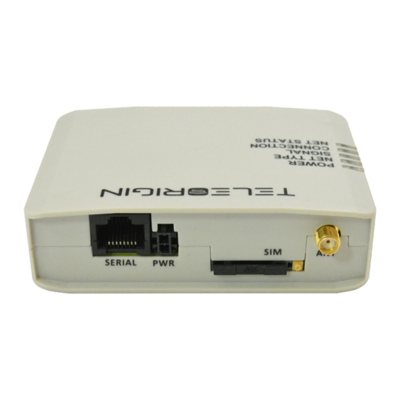
Page 8: General Presentation
General presentation Product pictures SMA antenna connector RJ45 connector (RS232/485/422) SIM card holder ejector Power Extractable SIM card supply holder LED’s POWER NET TYPE SIGNAL CONNECTION NET STATUS RESET button BOOT button... -
Page 9: External Connections
An SMA “GNSS” input is used to connect an external GPS/Glonass antenna. To establish connection with GPS/Glonass sattelites and check the coordinates of the device, an external antenna must be used and should be located outdoors. GNSS is optionally available in RB900SG-L2 and RB900SG-L5 modem variants. -
Page 10: Usb Interface
USB interface RB900SG terminal is equipped with a USB interface (as shown below). Type of connector is miniUSB. It is used for device configuration. -
Page 11: Rs232/Rs485/Rs422 Interfaces
RS232/RS485/RS422 interfaces The RB900SG terminal is equipped with RS232/RS485/RS422 interfaces on RJ45 socket. Use the jumper to switch between interfaces. All available jumper positions are presented in 7.1. Setting up the modem. The connector also carries the power supply from the ITRON SL7000 or ACE6000 meter, therefore it is not necessary to use an external power supply when connected to a meter. - Page 12 Pinout of the RJ45 - DB9 adapter (female) for the RS232 interface: RJ45 DB9 female RS232 1 VCC 4 TX 5 RX 6 GND 7 DTR...
-
Page 13: Power Supply Connector
Power supply connector The power supply connector is a 2-pin connector for external DC power supply connection, which can handle voltage from range 5..30 V DC, 2.5 W max. continuous power. (for modem with internal battery). Description 5 V…30 V DC Ground Attention! An attempt to power terminal from a DC source outside of 5..30 V range may result in the... -
Page 14: Sim Card Holder
SIM card holder A SIM card holder is placed at the front of the RB900SG terminal (as shown below), and is accessible externally. To insert a SIM card into the holder, press the yellow button, eject the little drawer, place the SIM card inside and insert drawer into the modem (you will hear „click”). -
Page 15: Product Sticker
Product sticker Product stickers are on the modem and on the box of the product. They includes the following informations and markings: product serial number (IMEI) • model signature • CE marking • 15-digit bar code • manufacturer address • Device sticker Box sticker... -
Page 16: Basic Features And Services
Basic features and services Basic features and available services for RB900SG are contained in table below. Feature/service Description Supported bands: RB900SG-L2: • Cat M1/Cat NB1: LTE FDD: B1/B2/B3/B4/B5/B8/B12/B13/B18/B19/B20/B26/B28 • LTE TDD: B39 (For Cat M1 Only) • EGPRS: 850/900/1800/1900MHz RB900SG-L5: •... -
Page 17: Using The Modem
Using the modem Setting up the modem To set up the modem, follow these steps: • At the production stage, the device is set up with a serial interface selected by the customer. If there is a need to change the serial interface, open the device housing and plug the jumper/jumpers on the appropriate connector of the internal board. - Page 18 • Connect the USB cable to the computer • Configure the modem using the Teleorigin Manager program. It is recommended to configure the modem without the SIM card inserted. Using the application, you can save the PIN code of the SIM card to the internal memory and set the APN, APN user name/password, change the antenna configuration (internal / external) and TCP/IP listening port.
- Page 19 • Insert the drawer into the modem. • Connect the modem with the meter using RJ45 cable (the modem will be powered directly from the meter) and mount it in the meter housing. For assembly description, see Modem assembly. • Now the modem is ready to work...
-
Page 20: Mounting The Modem
Mounting the modem To mount the modem inside the meter housing, please use one of the handles. The available handles are shown in the photos below. - Page 21 The method of mounting the modem in the ITRON SL7000 housing is shown in the photo below.
-
Page 22: Status Of The Modem (Leds)
Status of the modem (LEDs) The operation of the modem is indicated by LED diodes on the top of the device housing. The table below shows the description and signaling of the LEDs. LED name LED color Description POWER Lights when modem is power on NET TYPE green - on: LTE... -
Page 23: Text Commands
RB900SG SM STOP - stops the GSM machine RB900SG SM RESUME - resumes operation of the GSM state machine RB900SG TM CONNECTED - informs the device about the connection via the teleorigin manager RB900SG LOG PRINT - Send all entries from the event log... - Page 24 CONFIG SET RTC SOURCE GSM / NTP ntp_adr ntp_port - sets the internal clock sync source, ntp_adr and ntp_port must be omitted if GSM option is selected CONFIG GET RTC SOURCE GSM / NTP ntp_adr ntp_port - returns the internal clock synchronization source CONFIG SET NETWORK SEARCH MODE 2G/3G/4G/AUTO - sets the network search mode...
-
Page 25: Troubleshooting
• check that the COM port is correct. • check that the Teleorigin Manager program is working properly and that no other program is interfering with it. • when connecting the modem with the meter, check whether the meter is powered... -
Page 26: Technical Specifications
Technical specifications Mechanical specifications Max, dimensions 100 x 70 x 27 mm Weight ≈ 120 g Volume 170 cm Sketch of the housing... -
Page 27: Electrical Specification
Electrical specification Power supply Nominal voltage range: 5..30 V, 10%. • Maximum continous (average) supply range: 2.5 W. • Maximum continous (average) supply current: 200 mA at 12V, 100 mA at 24V. •... -
Page 28: Rf Specification
RF specification RB900SG-L2:... - Page 29 RB900SG-L5:...
- Page 32 RB900SG-E5: RB900SG-E1:...
- Page 33 RB900SG-U6: RB900SG-U5:...
-
Page 34: External Antenna
When the modem is placed in a room, or somewhere where the range of networks signal is too low, an outdoor or a specific indoor antenna should be used. Environmental characteristic Table below gives the environmental operating conditions of RB900SG terminal. Parameter Condition Unit Ambient operating °C... -
Page 35: Accessories
Accessories The pictures below show the available accessories for the RB900SG modem. RJ45 – RJ45 25cm cable: Meter handle 1... - Page 36 Meter handle 2: Wall handle: Screws for handles: LTE antenna:...
- Page 37 The product codes are listed in the table below. Accessory Product code RJ45 - RJ45 25cm cable RJ451125CMCA Handle 1 RB9HANDLEA1 Handle 2 RB9HANDLEA2 Wall handle RB9HANDLEA3 Screws for handles RB9SCREWS03 LTE antenna LTEANT0B04EX Internal antenna LTEANTP062IN Battery operation option ACC700B000IN (additional battery)
-
Page 38: Declaration Of Conformity
Declaration of conformity The RB900SG product was assessed with the participation of a Notified Body in terms of meeting the essential requirements of Directive 2014/53/EU (RED) regarding radio equipment to demonstrate compliance with harmonized standards. -
Page 39: Safety Recommendations
Safety Recommendations PREAD CAREFULLY Be sure the use of this product is allowed in the country and in the environment required. The use of this product may be dangerous and has to be avoided in the following areas: Where it can interfere with other electronic devices in environments such as hospitals, airports, aircrafts, etc Where there is risk of explosion such as gasoline stations, oil refineries, etc It is responsibility of the user to enforce the country regulation and the specific... - Page 40 the external components of the unit, as well as with any project or installation issue, because the risk of disturbing the GSM network and external devices, or having an impact on security. If in doubt, please refer to the technical documentation and the regulations in force. Every unit has to be equipped with a proper antenna with exact specifications.
-
Page 41: List Of Acronyms
List of acronyms Accumulated Call Meter ASCII American Standard Code for Information Interchange Attention commands Cell Broadcast Cell Broadcasting Service Call Control Meter CLIP Calling Line Identification Presentation CLIR Calling Line Identification Restriction CMOS Complementary Metal-Oxide Semiconductor Carriage Return Circuit Switched Data Clear To Send Digital Audio Interface Data Carrier Detected... - Page 42 Linefeed Mobile Equipment Man Machine Interface Mobile Originated Mobile Station Mobile Terminated Other Equipment Manufacturer Phone Book Protocol Data Unit Packet Handler Personal Identity Number PLMN Public Land Mobile Network PUCT Price per Unit Currency Table PIN Unblocking Code RACH Random Access Channel Radio Link Protocol Root Mean Square...
-
Page 43: Online Support
Elproma provides a range of online support which includes: • the latest version of this document • technical suport • latest version of Teleorigin Manager software and documentation This informations can be found also on our website at www.teleorigin.com For further information you can contact us at: E-mail: info@teleorigin.com...
Need help?
Do you have a question about the RB900SG and is the answer not in the manual?
Questions and answers