Table of Contents
Advertisement
Advertisement
Table of Contents

Related Manuals for Teleorigin RB800


Summary of Contents for Teleorigin RB800
-
Page 2: Table Of Contents
Contents 1. Overview..........................4 2. References.........................5 3.Product variants........................6 4. Package..........................7 4.1 Box............................7 5. Complete package contents....................8 6. General presentation......................9 6.1 Product pictures ........................9 6.2 External connections......................10 6.2.1 Antenna connector......................10 6.2.2 Memory slot........................10 6.2.3 USB Interface......................... 11 6.2.4 RS-232 Interface (EIA574)....................11 6.2.5 D-Sub HD 15-pin connector...................12 6.2.6 Power supply connector....................13 6.2.7 SIM card holder...................... - Page 3 9.2 Receiving ERROR message....................24 9.3 Receiving NO CARRIER message..................25 10. Technical characteristics....................26 10.1 Mechanical characteristic....................26 10.2 Housing description (dimensioning diagram)..............26 11. Electrical characteristic....................27 11.1 Power supply........................27 11.2 RF characteristics....................... 27 11.3 External antenna......................... 28 11.4 Environmental characteristic....................28 12. Python Script Interpreter....................29 13.
-
Page 4: Overview
1. Overview The RB800 Terminal is the complete modem solution for wireless m2m applications. Based on the Telit GL865 or UL865 module, it is available as quad or dual-band version and offers high level GSM/GPRS/UMTS features in compact aluminium housing with all the standardized interfaces. -
Page 5: References
2. References Telit_AT_Commands_Reference_Guide.pdf Telit_HE910_UE910_UL865_AT_Commands_Reference_Guide.pdf Telit_GL865-DUAL_QUAD_Product_Description.pdf Telit_UL865_Product_Description.pdf Telit_Easy_Script_Python_1.5.2.pdf Telit_Easy_Script_Python_2.7.pdf http://www.telit.com/en/products/umts.php?p_id=14&p_ac=show&p=145 http://www.python.org/... -
Page 6: Product Variants
3. Product variants Product variants, codes and description are listed below. RB800 - GL865 Quad (standard) - GL865 Dual - UL865 EUD - UL865 EUR GL865 Quad+MicroSD GL865 Dual+MicroSD UL865+MicroSD - standard option GPIO - 1SIM - 2SIM - RS232... -
Page 7: Package
4. Package 4.1 Box Original box of the product is shown in the picture below. You can find product sticker on the box. It matches modems sticker that is placed on the device. This proves that your modem is original product. More information about stickers Product sticker. -
Page 8: Complete Package Contents
5. Complete package contents Complete package contains: RB800 terminal (item A) GSM antenna (via SMA) (item B) wall handle (item C) power adaptor (item D) -
Page 9: General Presentation
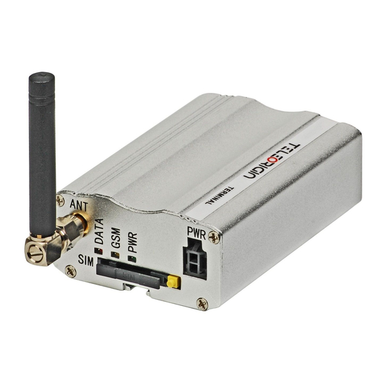
6. General presentation 6.1 Product pictures connector Power supply LED's DATA SIM card Extractable holder SIM card ejector holder EIA574 (RS-232) DE9 D-sub socket... -
Page 10: External Connections
6.2.2 Memory slot RB800 can be optionally equipped with memory card slot to store all the measured data. The slot type is microSD. Memory card can be controlled only by Python script using special AT commands which is sends through SER2 interface, see chapter Python Script... -
Page 11: Usb Interface
6.2.3 USB Interface RB800 terminal (only UMTS variant) is equipped with USB interface (as shown below) – miniUSB connector type. 6.2.4 RS-232 Interface (EIA574) RB800 terminal is equipped with RS-232 interface (as shown below). DE9 DSUB socket is connected via voltage level translator circuit to the GSM module. -
Page 12: D-Sub Hd 15-Pin Connector
6.2.5 D-Sub HD 15-pin connector RB800 can be equipped with DE9 15-pin connector to control RS232 interface and GPIO lines. GPIO lines can be controlled by internal Python application, see Python Script Interpreter and AT Reference manual for details. Below you can find pins... -
Page 13: Power Supply Connector
Table of RS-232 DB9 pins: Name Description Ground GPIO1 (ADC) IN/OUT General purpose input/output. ADC range 0..3V, 10 bit resolution. GPIO2 (ADC) IN/OUT General purpose input/output (high-drive 30mA). ADC range 0..3V, 10 bit resolution. Request To Send. Raised by DTE when it wishes to send. Expects CTS from DCE. -
Page 14: Sim Card Holder
6.2.7 SIM card holder SIM card holder is placed in front of RB800 terminal (as shown below) and is accessible externally. To insert SIM card into the holder press the yellow button, eject the little drawer, place there Your SIM card and insert drawer into the modem (You will hear click). -
Page 15: Basic Features And Services
7. Basic features and services Basic features and available services for RB800 are contained in table below. Feature/service Description Standard Supported Bands: UMTS variant: UMTS/HSPA 900/2100 Mhz (EUR/EUD version) UMTS/HSPA 850/1900 Mhz (NAR/NAD version) GSM/GPRS/EDGE 900/1800 MHz (EUR/EUD version) ... -
Page 16: Using The Modem
8. Using the modem 8.1 Setting up the modem To set up the modem, do the following steps: Eject SIM card holder using yellow button and pull out the drawer. Insert Your SIM card into drawer. Verify if SIM card fits in the drawer properly (as shown). ... -
Page 17: Mounting The Modem
Connect the antenna to the SMA connector Optionally it can be connected using RS-232 and miniUSB cables Plug the power supply cable to the power supply input Now the modem is ready to work. 8.2 Mounting the modem 8.2.1 On DIN bus To mount modem on DIN bus install DIN handle as shown below... -
Page 18: On The Wall
To mount modem on the wall install wall handles as shown below. 8.3 Checking the communication with the modem Once the modem is connected you can check communication between RB800 terminal and the PC using Telit AT Controller available here: http://teleorigin.com/file_upl/pliki/1/Telit_AT_Controller.zip... -
Page 19: Status Of The Modem (Leds)
For further information about AT commands and their usage, refer to [1]. 8.4 Status of the modem (LEDs) The operational status of the RB800 Terminal is signalized by external LEDs placed on the front panel of the modem. The table below shows what is the meaning of LEDs. -
Page 20: Verifying The Strength Of Received Signal
8.6 Verifying the strength of received signal RB800 terminal can establish connection with network if the received signal strength is sufficiently strong. To verify the signal strength and bit error rate, do the following: Using software such as Hyperterminal enter AT+CSQ. This command displays the received signal strength indication <rssi>... -
Page 21: Network Registration
8.8 Network registration 8.8.1 GSM network registration To check GSM network registration status enter AT+CREG? into software (for instance Hyperterminal) Modem will answer in following format: +CREG: <n>,<stat>[,<lac>,<ci>] The following table shows the +CREG parameters: <parameter> Description <n> 0 Disables the network registration unsolicited result code. 1 Enables the network registration unsolicited result code +CREG: <stat>. -
Page 22: Gprs Network Registration
8.9 GPRS network registration To check GPRS network registration status enter AT+CGREG? into software (for instance Hyperterminal) Modem will answer in following format: +CGREG: <n>,<stat>[,<lac>,<ci>] The following table shows the +CGREG parameters: <parameter> Description <n> 0 Disables the network registration unsolicited result code. 1 Enables the network registration unsolicited result code +CGREG: <stat>. -
Page 23: At Commands Summary
8.10 AT commands summary As a conclusion table below shows most common and useful AT commands. For more AT commands refer to [1]. Action Syntax Response Comments Echo enable ATE1 Typed text is seen. Echo disable ATE0 Typed text is not seen. Voice call ATD<phoneNo>;... -
Page 24: Troubleshooting
9. Troubleshooting 9.1 No connection/communication with the modem If there is no communication with the modem do the following steps: Check all external connections of the modem (RS-232 or USB, Power supply) Verify if power supply is correct (see Power supply) ... -
Page 25: Receiving No Carrier Message
9.3 Receiving NO CARRIER message There are some common cases when modem answers NO CARRIER: If data/voice/fax connection cannot be established Right after hanging up the data/voice/fax connection If there is no connection with network – check antenna and registration status (see Network registration) ... -
Page 26: Technical Characteristics
10. Technical characteristics 10.1 Mechanical characteristic Max. dimensions 72 x 53.5 x 26 mm (w/o connectors) 83 x 53.5 x 26 mm (w/ connectors) Weight ≈ 89 g Volume 100 cm (w/o connectors) 10.2 Housing description (dimensioning diagram) -
Page 27: Electrical Characteristic
11. Electrical characteristic 11.1 Power supply Nominal voltage range: 5..30 V, 10% Maximum continuous (average) supply power: 2.5 W Maximum continuous (average) supply current: 200 mA at 12V, 100 mA at 24V 11.2 RF characteristics GPRS variant: UMTS variant:... -
Page 28: External Antenna
11.4 Environmental characteristic Table below gives the environmental operating conditions of RB800 terminal. Attention! Exceeding the values may result in permanent damage to the module. -
Page 29: Python Script Interpreter
12. Python Script Interpreter The Easy Script Extension is a feature that allows driving the modem internally, writing the controlling application directly in the Python high level language. A typical application usually consists of a microcontroller managing several I/O pins on the module through the AT command interface. - Page 30 The Python script is executed in a task with the lowest priority on the Telit module, so it’s execution won’t interfere with GSM/GPRS normal operations. Furthermore, this allows serial ports, protocol stack etc. to run independently from the Python script. The Python script interacts with the Telit module functionalities through several built-in interfaces, as depicted below: ...
-
Page 31: At Reference Manual
13. AT Reference manual Important: the following table list of AT commands is available only for Python scripts to communicate with microcontroller through SER2 interface. COMMAND Function Starting a Command Line Command Echo #VER Device Version #GPIO General Purpose Input/Output Pin Control #ADC Analog/Digital Converter Input... - Page 32 12.1. Command Echo - E E - Command Echo ATE<n> Set command enables/disables the command echo. Parameter: <n> 0 - disables command echo 1 - enables command echo (default) , hence command sent to the device are echoed back to the DTE before the response is given. ATE? Read command current state in format: <n>...
- Page 33 #GPIO - General Purpose Input/Output Pin Control - output pin cleared to 0 (Low) if <dir>=1 - OUTPUT - no meaning if <dir>=2 - ALTERNATE FUNCTION 1 - no meaning if <dir>=0 - INPUT - output pin set to 1 (High) if <dir>=1 - OUTPUT - no meaning if <dir>=2 - ALTERNATE FUNCTION 2 - Reports the read value from the input pin (see Note).
- Page 34 #GPIO - General Purpose Input/Output Pin Control #GPIO: <dir>,<stat>,<pull> where <dir> - as seen before <stat> - as seen before <pull> - as seen before Example Read all inputs state: AT#GPIO? #GPIO: 0,1,1 #GPIO: 0,1,1 #GPIO: 0,1,1 #GPIO: 0,1,1 #GPIO: 0,1,1 #GPIO: 0,1,1 #GPIO: 0,1,1 Set GPIO1 as input with pull-up resistor...
- Page 35 12.4. Analog/Digital Converter Input - #ADC #ADC - Analog/Digital Converter Input AT#ADC=<adc> Execution command reads pin<adc> voltage, converted by ADC, and outputs it in the format: #ADC: <value> where: <value> - pin<adc> voltage, expressed in mV Parameters: <adc> - index of pin from 1 to 5 Example Set GPIO3 as ADC input with pull-up resistor AT#GPIO=3,0,2,1...
- Page 36 #I2C - I2C Bus Control operation. Any command is preceded by start condition and followed by stop condition. Write N bytes to slave device: N (number of SLAVE ADDR + W DATA 1 DATA N bytes to write) Response for write operation is only “OK” if succeed. Read N bytes from slave device: SLAVE ADDR + R N (number of bytes to read)
- Page 37 #I2C - I2C Bus Control Example Write 6 bytes to slave device with address 0x53, with 100kHz clock AT#I2C=0,"a60601aabbccddee" Read 5 bytes from slave device with address 0x53, with 400kHz clock AT#I2C=3,"a705" 0000000001 Read data is 0x00, 0x00, 0x00, 0x00, 0x01 Write 1 bytes and read 5 bytes from slave device with address 0x53, with repeated start condition.
- Page 38 #SLEEP – Power-down mode AT#SLEEP? Read current power mode state in format: #SLEEP: <n> where: <n> - as seen before 12.7. SD card status - #SD #SD – SD card status AT#SD=<n> Reset and initialize sd card. Parameter: <n> 1 - reset and initialize sd card. AT#SD? Read current sd card state in format: #SD: <n>,<size>...
- Page 39 12.8. SDRBLOCK read data block from memory card - #SDRBLOCK #SDRBLOCK – Read data block from memory card AT#SDRBLOCK= Read one sector (512 bytes) from memory card <sector> Parameter: <sector> - sector address to read, ascii hexadecimal format (max 8 characters) The microcontroler shall prompt a five character sequence: <<<...
- Page 40 #SDWBLOCK – Write data block to memory card <CR><LF><greater_than><greater_than><greater_than> after that 512 bytes can be send to microcontroler, in binary format. The operations completes when all the bytes are received. If writing ends successfully, the response is OK; otherwise an error is reported.
- Page 41 12.12 FREMOVE – removing a file or directory - #FREMOVE #FREMOVE – removing a file or directory AT#FREMOVE= Remove a directory or a file from a current location <name.ext> Where: - If it is a file: <name.ext> - string, name - max 8 characters, ext – max 3 characters - if it is a file: <name.ext>...
- Page 42 12.14 FCD – change current location - #FCD #FCD – change current location AT#FCD=<name> Change current location Where: <name> - string, name of directory with”\” before, to move in directory or with “\..” to move out from current directory Example Moving in directory “newdir”...
- Page 43 #FINIT – initialize FAT32 and set time and date AT#FINIT=2014,11,19,10,17,00 12.17 FWRITE – write a file - #FWRITE #FWRITE – write a file AT#FWRITE= Write to file <name.ext>,<offset> ,<mode>, Where: <byte_num>,<data> <name.ext> - as seen before <offset> - shift indicator in bytes <mode>...
-
Page 44: Safety Recommendations
14.2 Care and Maintenance The RB800 terminal is an electronic product that should be treated with care. Please follow suggestions shown below due to using modem for many years. Do not expose RB800 to any extreme circumstances like high temperature or high humidity ... -
Page 45: Accessories
15. Accessories The tables below shows recommended accessories for RB800 terminal. 15.1 Accessories critical for using modem Table below shows accessories critical for using modem. Without them usage of modem is impossible. Accessory Description Part no. Power adaptor Example of power adaptor is shown in the picture below... -
Page 46: Additional Accessories
15.2 Additional accessories Table below shows available accessories for RB800 modem series. Part No. Name Description RB-PS12VP2L15 12V power adaptor <1,5m> 2 PIN RB-PSCP2L15 Supply cable 2PIN <1,5m> open end RB-903G 3G angle antenna 2J010 RB-89MSH SIM drawer MOLEX 0912360001... -
Page 47: Conformity Assessment Issues
16. Conformity Assessment Issues The RB800 has been assessed in order to satisfy the essential requirements of the R&TTE Directive 1999/05/EC (Radio Equipment & Telecommunications Terminal Equipments) to demonstrate the conformity against the harmonised standards with the final involvement of a Notified Body. -
Page 48: Safety Recommendations
17. Safety Recommendations READ CAREFULLY Be sure the use of this product is allowed in the country and in the environment required. The use of this product may be dangerous and has to be avoided in the following areas: Where it can interfere with other electronic devices in environments such as •... -
Page 49: List Of Acronyms
18. List of Acronyms Accumulated Call Meter ASCII American Standard Code for Information Interchange Attention commands Cell Broadcast Cell Broadcasting Service Call Control Meter CLIP Calling Line Identification Presentation CLIR Calling Line Identification Restriction CMOS Complementary Metal-Oxide Semiconductor Carriage Return Circuit Switched Data Clear To Send Digital Audio Interface... - Page 50 Light Emitting Diode Linefeed Mobile Equipment Man Machine Interface Mobile Originated Mobile Station Mobile Terminated Other Equipment Manufacturer Phone Book Protocol Data Unit Packet Handler Personal Identity Number PLMN Public Land Mobile Network PUCT Price per Unit Currency Table PIN Unblocking Code RACH Random Access Channel Radio Link Protocol...
-
Page 51: On-Line Support
19. On-line support Elproma provides a range on on-line support which includes: the latest version of this document the latest drivers for RB800 technical support www.teleorigin.com This information can be found on our web sites at For further information You can contact us at: email: info@elproma.com.pl...
Need help?
Do you have a question about the RB800 and is the answer not in the manual?
Questions and answers