Table of Contents
Advertisement
Quick Links
Advertisement
Table of Contents

Related Manuals for Teleorigin RB900SG


Summary of Contents for Teleorigin RB900SG
-
Page 2: Table Of Contents
Contents 1. Overview..........................5 2. Product variants.........................6 3. Complete package contents....................7 4. General presentation......................8 4.1 Product pictures ........................8 4.2 External connections......................9 4.2.1GSM antenna connector....................9 4.2.2GNSS antenna connector....................9 4.2.3 USB Interface........................ 10 4.2.4 RS232/RS485/RS422 interfaces..................11 4.2.5 Power supply connector....................12 4.2.6 SIM card holder......................13 4.3 Product sticker........................ - Page 3 11. Accessories........................33 12. Conformity Assessment Issues..................34 13. Safety Recommendations....................35 14. List of Acronyms......................37 15. Online support........................39...
- Page 4 APPLICABILITY TABLE Modem Short description RB900SG-L2 2G+LTE Cat. M1 + LTE Cat. NB1 modem version RB900SG-L5 2G+LTE Cat. M1 + LTE Cat. NB2 modem version RB900SG-E5 4G Cat. 4 modem version RB900SG-E1 4G Cat. 1 modem version RB900SG-U6 3G Global modem version...
-
Page 5: Overview
1. Overview The RB900SG Terminal is the complete modem solution for wireless m2m applications. It offers high level LPWA/2G/3G/4G features and RS232/485/422 communication interfaces and USB interface for configuration. Together with its small size and wide power supply range, it is easy to integrate it with energy meters. -
Page 6: Product Variants
LTE Cat. 4 modem RB900SG-L2.X.X.2.X.X 2G/LTE Cat. M1 & NB1 modem RB900SG-L5.X.X.2.X.X 2G/LTE Cat. M1 & NB2 modem It is possible to use SIM-CHIP solution. Example P/N of the modem with SIM-CHIP: RB900SG-L2.X.C.2.X.X – 2G/LTE Cat. M1 & NB1 modem with SIM-CHIP... -
Page 7: Complete Package Contents
3. Complete package contents Complete package contains: RB900SG modem (item A) • RJ45 cable (item B) •... -
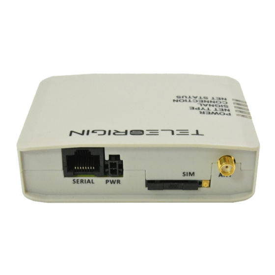
Page 8: General Presentation
4. General presentation 4.1 Product pictures connector Power supply SIM card holder ejector Power Extractable supply SIM card holder LED's POWER NET TYPE SIGNAL CONNECTION NET STATUS RESET button BOOT button... -
Page 9: External Connections
An SMA “GNSS” input is used to connect an external GPS/Glonass antenna. To establish connection with GPS/Glonass sattelites and check the coordinates of the device, an external antenna must be used and should be located outdoors. GNSS is optionally available in RB900SG-L2 and RB900SG-L5 modem variants. -
Page 10: Usb Interface
4.2.3 USB Interface RB900SG terminal is equipped with a USB interface (as shown below). Type of connector is miniUSB. It is used for device configuration. -
Page 11: Rs232/Rs485/Rs422 Interfaces
4.2.4 RS232/RS485/RS422 interfaces The RB900SG terminal is equipped with RS232/RS485/RS422 interfaces in RJ45 socket. Use the jumper to switch between interfaces. All available jumper positions are presented in 7.1. Setting up the modem Table of RJ45 serial connector: Connector RJ6... -
Page 12: Power Supply Connector
4.2.5 Power supply connector The power supply connector is a 2-pin connector for external DC power supply connection, which can handle voltage from range 5..30 V DC, 2.5 W max. continuous power. Singal Description V+BATTERY 5 V – 30 V DC Ground Attention! An attempt to power terminal from a DC source outside of 5..30 V range may result in the... -
Page 13: Sim Card Holder
4.2.6 SIM card holder A SIM card holder is placed at the front of the RB900SG terminal (as shown below), and is accessible externally. To insert a SIM card into the holder, press the yellow button, eject the little drawer, place the SIM card inside and insert drawer into the modem (you will hear „click”). -
Page 14: Product Sticker
4.3 Product sticker Product stickers are on the modem and on the box of the product. They includes the following informations and markings: product serial number (IMEI) • model signature • CE marking • 15-digit bar code • manufacturer address •... -
Page 15: Basic Features And Services
5. Basic features and services Basic features and available services for RB900SG are contained in table below. Feature/service Description Supported Bands: RB900SG-L2: • Cat M1/Cat NB1: LTE FDD: B1/B2/B3/B4/B5/B8/B12/B13/B18/B19/B20/B26/B28 • LTE TDD: B39 (For Cat M1 Only) • EGPRS: 850/900/1800/1900MHz RB900SG-L5: •... -
Page 16: Using The Modem
6. Using the modem 6.1 Setting up the modem To set up the modem, follow these steps: Eject SIM card holder using yellow button and pull out the drawer. •... - Page 17 Insert your SIM card into drawer. • Verify if SIM card fits in the drawer properly (as shown below). • Insert the drawer into the modem. •...
- Page 18 Insert a jumper to one of the connector to set the right serial port. Possible jumper positions • are described in a picture below RS422 RS232 RS485...
- Page 19 Plug the power supply cable into the power supply input • Connect the modem using RS232/RS485/RS232 RJ45 cable to meter or miniUSB cable to PC • with configuration software Now the modem is ready to work. •...
-
Page 20: Mounting The Modem
6.2 Mounting the modem To mount the modem inside the meter housing, please use one of the handles. -
Page 21: Checking The Communication With The Modem
6.3 Checking the communication with the modem Once the modem is connected you can check communication between RB900SG terminal and the PC using RB-Setup configuration software which is available here: http://download.teleorigin.com/RBSetupInstall.exe To communicate with the modem, use USB interface. Using application you can set SIM PIN, APN, username/password, antenna configuration and TCP listen port. -
Page 22: Status Of The Modem (Leds)
6.4 Status of the modem (LEDs) The operational status of the RB900SG Terminal is shown by external LEDs placed on the front panel of the modem. The table below shows what is the meaning of LEDs. LED color Description name... -
Page 23: Troubleshooting
7. Troubleshooting 7.1 No connection/communication with the modem If there is no communication with the modem take the following steps: Check all external connections of the modem (serial interfaces, USB, power supply) • Verify if the power supply is correct (see Power supply) •... -
Page 24: Technical Specifications
8. Technical specifications 8.1 Mechanical specifications Max. dimensions 100 x 70 x 27 mm Weight ≈ 120 g Volume 170 cm 8.2 Housing description (dimension diagram) -
Page 25: Electrical Specification
9. Electrical specification 9.1 Power supply Nominal voltage range: 5..30 V, 10% • Maximum continuous (average) supply power: 2.5 W • Maximum continuous (average) supply current: 200 mA at 12V, 100 mA at 24V • 9.2 RF specifications RB900SG-L2:... - Page 26 RB900SG-L5:...
- Page 29 RB900SG-E5: RB900SG-E1:...
- Page 30 RB900SG-U6: RB900SG-U5:...
-
Page 31: External Antenna
9.4 Environmental characteristic Table below gives the environmental operating conditions of RB900SG terminal. Attention! Exceeding the values may result in permanent damage to the module. -
Page 32: Safety Recommendations
GSM modem or the other equipment. 10.2 Care and Maintenance The RB900SG terminal is an electronic product that should be treated with care. Please follow the suggestions shown below to ensure the modem's life for many years. Do not expose RB900SG to any extreme circumstances like high temperature or •... -
Page 33: Accessories
11. Accessories The picture below shows accessories for RB900SG terminal. Accessories are listed in a table below. Accessory Part no. Power adaptor Power cable Antenna Screws... -
Page 34: Conformity Assessment Issues
12. Conformity Assessment Issues The RB900SG has been assessed in order to satisfy the essential requirements of the RED 2014/53/EU directive to demonstrate the conformity against the harmonised standards with the final involvement of a Notified Body. -
Page 35: Safety Recommendations
13. Safety Recommendations READ CAREFULLY Be sure the use of this product is allowed in the country and in the environment required. The use of this product may be dangerous and has to be avoided in the following areas: Where it can interfere with other electronic devices in environments such as •... - Page 36 taken when handling the SIM, please carefully check the instructions for its use. Do not insert or remove the SIM when the product is in power saving mode. The system integrator is responsible for the functioning of the final product; therefore, care has to be taken with the external components of the unit, as well as with any project or installation issue, because the risk of disturbing the GSM network and external devices, or having an impact on security.
-
Page 37: List Of Acronyms
14. List of Acronyms Accumulated Call Meter ASCII American Standard Code for Information Interchange Attention commands Cell Broadcast Cell Broadcasting Service Call Control Meter CLIP Calling Line Identification Presentation CLIR Calling Line Identification Restriction CMOS Complementary Metal-Oxide Semiconductor Carriage Return Circuit Switched Data Clear To Send Digital Audio Interface... - Page 38 Light Emitting Diode Linefeed Mobile Equipment Man Machine Interface Mobile Originated Mobile Station Mobile Terminated Other Equipment Manufacturer Phone Book Protocol Data Unit Packet Handler Personal Identity Number PLMN Public Land Mobile Network PUCT Price per Unit Currency Table PIN Unblocking Code RACH Random Access Channel Radio Link Protocol...
-
Page 39: Online Support
Elproma provides a range of online support which includes: the latest version of this document • technical support • www.teleorigin.com This information can be found on our website at For further information you can contact us at: E-mail: info@elpromaelectronics.com Telephone: +48 22 751 76 80...
Need help?
Do you have a question about the RB900SG and is the answer not in the manual?
Questions and answers