Table of Contents
Advertisement
Quick Links
Advertisement
Table of Contents

Related Manuals for Teleorigin RB900 Series


Summary of Contents for Teleorigin RB900 Series
-
Page 2: Table Of Contents
Contents 1. Overview..........................5 2. References.........................6 3. Product variants.........................7 4.Package..........................8 4.1 Box............................8 5. Complete package contents....................9 6. General presentation.......................10 6.1 Product pictures ........................10 6.2 External connections......................11 6.2.1 GSM antenna connector....................11 6.2.2 GPS antenna connector....................11 6.2.3 Memory slot........................12 6.2.4 USB Interface........................ 12 6.2.5 RS232 Interface (EIA574).....................13 6.2.6 RS485 interface...................... - Page 3 9. Troubleshooting........................28 9.1 No connection/communication with the modem..............28 9.2 Receiving ERROR message....................28 9.3 Receiving NO CARRIER message..................29 10. Technical characteristics....................30 10.1 Mechanical characteristic....................30 10.2 Housing description (dimensioning diagram)..............30 11. Electrical characteristic....................31 11.1 Power supply........................31 11.2 RF characteristics....................... 31 11.3 External antenna......................... 33 11.4 Environmental characteristic....................33 12.
- Page 4 APPLICABILITY TABLE Modem Short description RB900 Basic GPRS modem RB900-IO GPRS modem with GPIO signals RB900-M GPRS modem with memory card connector RB900-GPS GPRS modem with GPS/Glonass receiver RB900MODBUS GPRS modem with Modbus application RB900U Basic UMTS modem RB900U-IO UMTS modem with GPIO signals RB900U-M UMTS modem with memory card connector RB900U-GPS...
-
Page 5: Overview
1. Overview The RB900 Terminal is the complete modem solution for wireless m2m applications. Based on the Telit GE910, HE910 or LE910 module, it is available as penta or quad-band versions and offers high level GSM/GPRS/HSPA+/LTE features in a compact aluminium housing with all the standardized interfaces and optional GPS receiver, configurable GPIO or memory card to store all the measured data. -
Page 6: References
2. References Telit_AT_Commands_Reference_Guide.pdf Telit_3G_Modules_AT_Commands_Reference_Guide.pdf Telit_LE9x0_AT_Commands_Reference_Guide.pdf Telit_GE910_Product_Description.pdf Telit_HE910-Series_Product_Description.pdf Telit_LE910_Product_Description.pdf Telit_Easy_Script_Python.pdf Telit_Easy_Script_Python_2.7.pdf Telit_IoT_AppZoneC_API_Reference Guide.pdf [10] http://www.python.org/... -
Page 7: Product Variants
3. Product variants RB900 modem variants, order codes and its description are listed below. RB900 - GE910 - HE910 - LE910 GE910+MicroSD HE910+MicroSD LE910+MicroSD - standard option GPIO only INPUT only OUTPUT option GPS IO GPS - option IO + GPS - 1SIM - 2SIM - RS232... -
Page 8: Package
4. Package 4.1 Box Original box of the product is shown in the picture below. There is product sticker on the box. It matches the sticker that is placed on the device. This verifies that your modem is an original product. More information about stickers in chapter 6.3... -
Page 9: Complete Package Contents
5. Complete package contents Complete package contains: • RB900 terminal (item A) • GSM antenna (SMA connector) (item B) • wall bracket (item C) • power adaptor (item D) -
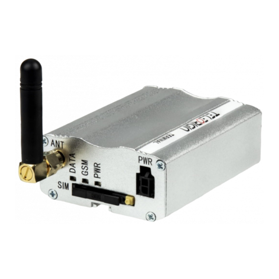
Page 10: General Presentation
6. General presentation 6.1 Product pictures connector Power supply LED's DATA SIM card Extractable holder SIM card ejector holder EIA574 (RS-232) DE9 D-sub socket... -
Page 11: External Connections
6.2 External connections 6.2.1 GSM antenna connector An SMA “ANT” input is used to connect external GSM antenna. To establish a connection with a GSM network, an external antenna must be used. Type of antenna depends of GSM coverage. In good circumstances (level of received signal is high) use antenna contained in the package. -
Page 12: Memory Slot
6.2.3 Memory slot The RB900 can be optionally equipped with a memory card slot to store all the measured data. The slot type is microSD. The memory card can be controlled by a Python script using special AT commands which is sends through SER2 interface, see chapter AT Reference manual and Python Script Interpreter. -
Page 13: Rs232 Interface (Eia574)
6.2.5 RS232 Interface (EIA574) The RB900 terminal is equipped with an RS232 interface (as shown below). The DE9 DSUB socket is connected via a voltage level translator circuit to the GSM module. Table of RS232 DB9 pins: Pin No. Name Description Data Carrier Detect. -
Page 14: Rs485 Interface
6.2.6 RS485 interface RB900 terminal can be optionally equipped with an RS485 half duplex interface (RS232 or RS485, not both). The DE9 DSUB socket is connected via a voltage level translator circuit to the GSM module. Table of RS485 DB9 pins: Pin No. -
Page 15: D-Sub Hd 15-Pin Connector
6.2.7 D-Sub HD 15-pin connector The RB900 can be equipped with a DE9 15-pin connector to control the RS232 interface and GPIO lines. The GPIO lines can be controlled by standard AT commands (AT#GPIO) or by an internal Python application using MDM.send('AT#GPIO?\r',0) MDM.read() functions. - Page 16 Possible GPIO configurations: • 7 inputs 3.3V • 7 inputs 5-24V • 6 inputs 3.3V + power supply on pin 7 (3.3V or device power supply) • 6 inputs 5-24V + power supply on pin 7 (3.3V or device power supply) •...
-
Page 17: Power Supply Connector
6.2.8 Power supply connector The power supply connector is a 2-pin connector for external DC power supply connection, which can handle voltage from range 5..30 V DC, 2.5 W max. continuous power. Singal Description V+BATTERY 5 V – 30 V DC Ground Attention! An attempt to power terminal from a DC source outside of 5..30 V range may result in the... -
Page 18: Product Sticker
Product sticker Product stickers are on the modem and on the box of the product. The production sticker includes the following information: • product serial number (IMEI) • the CE marking • the 15-digit bar code • the model signature Device sticker Box sticker... -
Page 19: Basic Features And Services
7. Basic features and services Basic features and available services for RB900 are contained in table below. Feature/service Description Standard Supported Bands: LTE variant: EU version: - 800/1800/2600 Mhz LTE - 900/2100 Mhz UMTS - 850/900/1800/1900 Mhz GSM/GPRS/EDGE NA variant: - 700/850/AWS1700/1900 Mhz LTE - 850/1900 Mhz UMTS - 850/1900 Mhz GSM/GPRS/EDGE... -
Page 20: Using The Modem
8. Using the modem 8.1 Setting up the modem To set up the modem, follow these steps: • Eject SIM card holder using yellow button and pull out the drawer. • Insert Your SIM card into drawer. • Verify if SIM card fits in the drawer properly (as shown). •... -
Page 21: Mounting The Modem
• Connect the antenna to the SMA connector • Optionally it can be connected using RS-232 and miniUSB cables • Plug the power supply cable into the power supply input • Now the modem is ready to work. 8.2 Mounting the modem 8.2.1 On DIN bus To mount modem on DIN bus install DIN bracket as shown below... -
Page 22: On The Wall
Once the modem is connected you can check communication between RB900 terminal and the PC using Telit AT Controller available here: http://www.teleorigin.com/file_upl/pliki/1/Telit_AT_Controller_r3_4_4.zip You can also use any other Terminal program. Configuration of the DTE (port COM) should be as follows: •... -
Page 23: Status Of The Modem (Leds)
• AT+CPIN=xxxx to enter PIN, where 'xxxx' are digits • AT+CSQ to verify received signal strength • ATD<phone_number>; to initiate a voice call • ATH to hang up a voice call For further information about AT commands and their usage, refer to [1]. 8.4 Status of the modem (LEDs) The operational status of the RB900 Terminal is shown by external LEDs placed on the front panel of the modem. -
Page 24: Verifying The Strength Of Received Signal
8.6 Verifying the strength of received signal RB900 terminal can establish a connection with a network if the received signal strength is sufficiently strong. To verify the signal strength and bit error rate, do the following: Using software such as Hyperterminal enter AT+CSQ. This command displays the received signal strength indication <rssi>... -
Page 25: Network Registration
8.8 Network registration 8.8.1 GSM network registration To check the GSM network registration status, enter AT+CREG? Into the software (for instance Hyperterminal). The modem will answer in the following format: +CREG: <n>,<stat>[,<lac>,<ci>] The following table shows the +CREG parameters: <parameter> Description <n>... -
Page 26: Gprs Network Registration
8.9 GPRS network registration To check the GPRS network registration status, enter AT+CGREG? into the software, (for instance Hyperterminal). The modem will answer in following format: +CGREG: <n>,<stat>[,<lac>,<ci>] The following table shows the +CGREG parameters: <parameter> Description <n> 0 Disables the network registration unsolicited result code. 1 Enables the network registration unsolicited result code +CGREG: <stat>. -
Page 27: At Commands Summary
8.10 AT commands summary As a conclusion table below shows most common and useful AT commands. For more AT commands refer to [1]. Action Syntax Response Comments Echo enable ATE1 Typed text is seen. Echo disable ATE0 Typed text is not seen. Voice call ATD<phoneNo>;... -
Page 28: Troubleshooting
9. Troubleshooting 9.1 No connection/communication with the modem If there is no communication with the modem take the following steps: • Check all external connections of the modem (RS-232 or USB, Power supply) • Verify if the power supply is correct (see Power supply Power supply) •... -
Page 29: Receiving No Carrier Message
9.3 Receiving NO CARRIER message There are some common cases when the modem answers NO CARRIER: • If a data/voice/fax connection cannot be established • Right after hanging up the data/voice/fax connection • If there is no connection with the network – check antenna and registration status (see Network registration) •... -
Page 30: Technical Characteristics
10. Technical specifications 10.1 Mechanical specifications Max. dimensions 72 x 53.5 x 26 mm (w/o connectors) 83 x 53.5 x 26 mm (w/ connectors) Weight ≈ 89 g Volume 100 cm (w/o connectors) 10.2 Housing description (dimension diagram) -
Page 31: Electrical Characteristic
11. Electrical specification 11.1 Power supply • Nominal voltage range: 5..30 V, 10% • Maximum continuous (average) supply power: 2.5 W • Maximum continuous (average) supply current: 200 mA at 12V, 100 mA at 24V 11.2 RF specifications GPRS variant: LTE variant:... - Page 32 HSPA + variant:...
-
Page 33: External Antenna
11.3 External antenna The external antenna is connected to the modem via an SMA connector. The antenna must have the parameters shown below in the table. Antenna frequency range Supporting GSM, UMTS or LTE frequencies Impedance 50 Ω DC impedance 0 Ω... -
Page 34: Python Script Interpreter
12. Python Script Interpreter The Easy Script Extension is a feature that allows driving the modem internally, writing the controlling application directly in the Python high level language. Python feature is available in GPRS and HSPA+ modem variants only. A typical application usually consists of a microcontroller managing several I/O pins on the module through the AT command interface. - Page 35 The Python script is executed in a task with the lowest priority on the Telit module, so it’s execution won’t interfere with normal GSM/GPRS operations. Furthermore, this allows serial ports, protocol stack etc. to run independently from the Python script. The Python script interacts with the Telit module functions through several built-in interfaces, as depicted below: •...
-
Page 36: Appzone
13. AppZone AppZone is a Telit's software layer built on the top of the basic software of the module that provides a set of interfaces to the most of the module functionalities, e.g.: GSM/GPRS services and hardware resources. The AppZone layer allows the M2M “C” language application of the customer to run on the CPU of the module. -
Page 37: Rb900-Gps
14. RB900-GPS RB900-GPS modem variant includes a high-precision combo GPS+Glonass receiver with external antenna. GPS antenna connector type is SMA. Below is the short specification and parameters of the GPS/Glonass receiver. Frequency bands: GPS (L1), Glonass (L1, FDMA), Galileo (E1) Standards: NMEA, RTCM 32 Channel GPS architecture Sensitivity:... -
Page 38: Rb900Modbus
15. RB IndustrialRT RB IndustrialRT is a fully functional GSM/GPRS modem (please refer to RB900 specification) with additional hardware and a programmable module. Beside the RB900 hardware it has a built-in RS485 module next to the RS232 module (available for use one at a time). RB IndustrialRT can be controlled similarly to RB900, using AT commands and Python scripts, as well as by a MODBUS application written in C, which is prepared individually after contacting our R&D department. -
Page 39: At Reference Manual
16. AT Reference manual Important: the following table list of AT commands is only suitable for Python scripts to communicate with the microcontroller through the SER2 interface. COMMAND Function Starting a Command Line Command Echo #VER Device Version #SLEEP Switch device into power-down mode SD card status #SDRBLOCK Read data block from SD card... - Page 40 16.2. Device Version - #VER #VER – Device Version AT#VER Read software and hardware version in format: AT#VER=<swver><hwver> where <swver> - version of microcontroler software <hwver> - version of hardware 16.3. Power-down mode - #SLEEP #SLEEP – Power-down mode AT#SLEEP=<n> Set power-down mode.
- Page 41 #SD – SD card status AT#SD? Read current sd card state in format: #SD: <n>,<size> where: <n> 0 - sd card not detected 1 - sd card initialized 2 - sd card initialization failed <size> - number of sectors in user area, hexadecimal format. Example AT#SD? AT#SD: 1,001E4600...
- Page 42 #SDRBLOCK – Read data block from memory card 0123456789abcd_f0123456789abcdef0123456789abcdef0123456789abc def0123456789abcdef0123456789abcdef0123456789abcdef0123456789 abcdef0123456789abcdef0123456789abcdef0123456789abcdef0123456 789abcdef0123456789abcdef0123456789abcdef0123456789abcdef0123 456789abcdef0123456789abcdez 16.6. SDWBLOCK write data block to memory card - #SDWBLOCK #SDWBLOCK – Write data block to memory card AT#SDWBLOCK= Write one sector (512 bytes) to memory card <sector>...
-
Page 43: Safety Recommendations
17. Safety recommendations 17.1 General Safety Please follow safety regulations regarding the use of radio equipment due to the possibility of radio frequency interference. Read the following advice carefully. Switch off GSM terminal when: • in an aircraft – using cellular telephones in aircraft may endanger the operation of the aircraft;... -
Page 44: Accessories
18. Accessories The tables below shows recommended accessories for RB900 terminal. 18.1 Accessories critical for using modem Table below shows accessories critical for using modem. Without them, usage of the modem is impossible. Accessory Description Part no. Power adaptor Example of power adaptor is shown in the picture below Power adaptor 6V... -
Page 45: Additional Accessories
18.2 Additional accessories Table below shows available accessories for RB900 modem series. Part No. Name Description RB-PS12VP2L15 12V power adaptor <1,5m> 2 PIN RB-PSCP2L15 Supply cable 2PIN <1,5m> open end RB-903G 3G angle antenna 2J010 RB-89MSH SIM drawer MOLEX 0912360001 RB-89DH DIN Holder RB-89WMK... -
Page 46: Conformity Assessment Issues
19. Conformity Assessment Issues The RB900 has been assessed in order to satisfy the essential requirements of the RED 2014/53/EU directive to demonstrate the conformity against the harmonised standards with the final involvement of a Notified Body. -
Page 47: Safety Recommendations
20. Safety Recommendations READ CAREFULLY Be sure the use of this product is allowed in the country and in the environment required. The use of this product may be dangerous and has to be avoided in the following areas: • Where it can interfere with other electronic devices in environments such as hospitals, airports, aircrafts, etc •... - Page 48 taken when handling the SIM, please carefully check the instructions for its use. Do not insert or remove the SIM when the product is in power saving mode. The system integrator is responsible for the functioning of the final product; therefore, care has to be taken with the external components of the unit, as well as with any project or installation issue, because the risk of disturbing the GSM network and external devices, or having an impact on security.
-
Page 49: Certifications
21. Certifications Name: Industrial GSM/GPRS mdoem Model: RB900 Reference standard(s): RF spectrum use (R&TTE art. 3.2) EN 301 511 V9.02 EMC (R&TTE art. 3.1b) EN 301 489-1 V1.9.2 EN 301 489-7 V1.3.1 Health & Safety (R&TTE art. 3.1a) EN 60950-1 Name: Industrial GSM/HSPA+ mdoem Model: RB900U Reference standard(s):... - Page 50 Name: Industrial GSM/LTE mdoem Model: RB900L Reference standard(s): R&TTE 1999/5/EC RF spectrum use (R&TTE art. 3.2) EEN300 440-2 V1.4.1 N 301 511 V9.02 EN 301 908-1 V6.2.1 EN 301 908-2 V5.4.1 EN 301 908-2 V5.2.1 EMC (R&TTE art. 3.1b) EN 301 489-1 V1.9.2 EN 301 489-3 V1.6.1 EN 301 489-7 V1.3.1 EN 301 489-24 V1.5.1 EN 55022 Class B Health &...
-
Page 51: List Of Acronyms
22. List of Acronyms Accumulated Call Meter ASCII American Standard Code for Information Interchange Attention commands Cell Broadcast Cell Broadcasting Service Call Control Meter CLIP Calling Line Identification Presentation CLIR Calling Line Identification Restriction CMOS Complementary Metal-Oxide Semiconductor Carriage Return Circuit Switched Data Clear To Send Digital Audio Interface... - Page 52 Light Emitting Diode Linefeed Mobile Equipment Man Machine Interface Mobile Originated Mobile Station Mobile Terminated Other Equipment Manufacturer Phone Book Protocol Data Unit Packet Handler Personal Identity Number PLMN Public Land Mobile Network PUCT Price per Unit Currency Table PIN Unblocking Code RACH Random Access Channel Radio Link Protocol...
-
Page 53: Online Support
• the latest drivers for RB900 • technical support www.teleorigin.com This information can be found on our web sites at For further information you can contact us at: email: info@elpromaelectronics.com tel.: +48 (22) 751 76 80 fax.: +48 (22) 751 76 81...
Need help?
Do you have a question about the RB900 Series and is the answer not in the manual?
Questions and answers