
Related Manuals for Beckman Coulter SA 3100 Series


Summary of Contents for Beckman Coulter SA 3100 Series
- Page 2 WARNINGS, CAUTIONS, and IMPORTANTS alert you as follows: WARNING - Might cause injury. CAUTION - Might cause damage to the instrument. IMPORTANT - Might cause misleading results.
- Page 3 Updated trademark information Updated all instances of Coulter Corporation or Coulter Electronics to Beckman Coulter, Inc. Revised the address to the Beckman Coulter address Deleted the Coulter Care Symbol (CC) PN 4237215AA (October 2011)
- Page 4 PN 4237215AA (October 2011)
- Page 5 PN 4237215AA (October 2011)
- Page 6 PN 4237215AA (October 2011)
- Page 7 PN 4237215AA (October 2011)
- Page 8 PN 4237215AA (October 2011)
- Page 9 > > > > > > > PN 4237215AA (October 2011)
- Page 10 PN 4237215AA (October 2011)
- Page 11 PN 4237215AA (October 2011)
- Page 12 PN 4237215AA (October 2011)
- Page 13 xiii PN 4237215AA (October 2011)
- Page 14 PN 4237215AA (October 2011)
- Page 15 PN 4237215AA (October 2011)
- Page 16 PN 4237215AA (October 2011)
- Page 17 Screens Analysis Outgas Profiles Analysis PN 4237215AA (October 2011)
- Page 18 > PN 4237215AA (October 2011)
- Page 19 PN 4237215AA (October 2011)
- Page 20 PN 4237215AA (October 2011)
- Page 21 PN 4237215AA (October 2011)
- Page 22 PN 4237215AA (October 2011)
- Page 23 PN 4237215AA (October 2011)
- Page 24 PN 4237215AA (October 2011)
- Page 25 Figure 3.1 Shipping lnsert PN 4237215AA (October 2011)
- Page 26 Vacuum Pump CAUTION Use only Balzers P3 pump oil in the vacuum pump. Use of other oil may damage the pump and will void the pump warranty. PN 4237215AA (October 2011)
- Page 27 Figure 3.3 lnstalling Oil Mist Filter CAUTION Do not attach the vacuum line to the oil mist filter connector. Doing so may damage the pump and the SA 3100 analyzer. PN 4237215AA (October 2011)
- Page 28 Figure 3.4 Connecting Vacuum Line to the Vacuum Pump PN 4237215AA (October 2011)
- Page 29 PN 4237215AA (October 2011)
- Page 30 Figure 3.6 Placing Vacuum Pump into Pump Shelf PN 4237215AA (October 2011)
- Page 31 Figure 3.7 Optional Pressure Regulator Kit Installation WARNING The regulator supplied is designed for only nitrogen, helium, and other inert gases. The regulator must not be used for any corrosive or hazardous gas. WARNING To prevent valve damage and potential personal injury, never use a nonstandard wrench or tool on any cylinder valve.
- Page 32 WARNING To prevent valve damage and personal injury, do not force the regulator-cylinder connection. If the regulator does not screw into the cylinder valve outlet easily, check for cross-threading or contamination. CAUTION Never use oil, grease, or Teflon tape on any cylinder or regulator valve or connection threads.
- Page 33 IMPORTANT The cylinder pressure must be at least 100 psig. 3-11 PN 4237215AA (October 2011)
- Page 34 Figure 3.8 Gas Line Connections to the Analyzer 3-12 PN 4237215AA (October 2011)
- Page 35 IMPORTANT The cylinder pressure must be at least 100 psig. 3-13 PN 4237215AA (October 2011)
- Page 36 CAUTION To prevent damage to ports or fittings, do not use any tools to remove or install port fittings. Fittings are designed to seal when finger-tight. Figure 3.9 Port Fittings IMPORTANT Excess grease on O-rings will be deposited on sample tubes, causing weighing and analysis errors.
- Page 37 Figure 3.1 0 Seating the O-ring 3-15 PN 4237215AA (October 2011)
- Page 38 CAUTION Do not use any tools to remove or install saturation port, adsorption port, or outgas port fittings. Fittings are designed to seal when finger-tight. Figure 3.1 1 Saturation Tube, lnsert and Heat Sink 3-16 PN 4237215AA (October 2011)
- Page 39 Figure 3.1 2 Saturation Tube Installation Analysis 3-17 PN 4237215AA (October 2011)
- Page 40 Figure 3.1 3 Analyzer Power-up Figure 3.1 4 Analysis Screen 3-18 PN 4237215AA (October 2011)
- Page 41 Analysis Setup and Print Analysis 3-19 PN 4237215AA (October 2011)
- Page 42 Figure 3.1 5 Printer Installation Analysis Setup Configuration Configuration Printers Configuration Analysis Advanced Setup 3-20 PN 4237215AA (October 2011)
- Page 43 > PN 4237215AA (October 2011)
- Page 44 PN 4237215AA (October 2011)
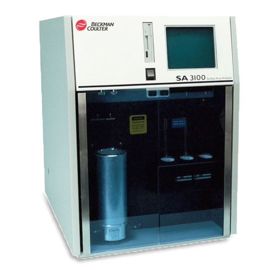
- Page 45 > Figure 4.1 SA 31 00 Analyzer Front View PN 4237215AA (October 2011)
- Page 46 Figure 4.2 SA 3100 Analyzer Back View > PN 4237215AA (October 2011)
- Page 47 PN 4237215AA (October 2011)
- Page 48 > Figure 4.3 Analysis Screen Analysis PN 4237215AA (October 2011)
- Page 49 Figure 4.4 Example of Nurneric Keypad on the Touch Screen Figure 4.5 Example of Alphanumeric (QWERTY) Keypad on the Touch Screen PN 4237215AA (October 2011)
- Page 50 Analysis Analysis Analysis Analysis PN 4237215AA (October 2011)
- Page 51 Outgas Figure 4.6 Outgas Screen Outgas Outgas Analysis Analysis PN 4237215AA (October 2011)
- Page 52 Profile Figure 4.7 Profile Screen > > > Sample Information > 4-10 PN 4237215AA (October 2011)
- Page 53 PN 4237215AA (October 2011)
- Page 54 Figure 5.1 Sample Tube Assembly PN 4237215AA (October 2011)
- Page 55 Figure 5.2 Weighing the Sample Tube Assembly > PN 4237215AA (October 2011)
- Page 56 Figure 5.3 Adding Sarnple to the Sarnple Tube Analysis Outgas Outgas Outgas PN 4237215AA (October 2011)
- Page 57 Figure 5.4 Analysis Screen Analysis Outgas Figure 5.5 Outgas Screen Outgas Outgas Sample Information Sample Information screen PN 4237215AA (October 2011)
- Page 58 > > Profiles Figure 5.6 Sample lnformation Screen PN 4237215AA (October 2011)
- Page 59 CAUTION Do not use any tools to remove or install saturation tube or adsorption tube fittings. Fittings are designed to seal when finger-tight Figure 5.7 Connecting the Sample Tube to an Outgas Port PN 4237215AA (October 2011)
- Page 60 > Outgas Outgas Outgas Outgas Outgas PN 4237215AA (October 2011)
- Page 61 Figure 5.8 Weighing the Sample Tube Assembly with Sample after Outgassing IMPORTANT Do not load the sample tube onto the analysis port until instructed to do so by a message on the touch screen. Doing so may compromise analysis results. Analysis Outgassed Samples Sample Information...
- Page 62 Figure 5.9 Outgassed Samples Screen Sample Information Analysis 5-10 PN 4237215AA (October 2011)
- Page 63 Figure 5.10 Attaching Sarnple Tube to Analysis Port WARNING Use proper safety equipment when handling liquid nitrogen, including, but not limited to, safety glasses and low temperature thermal gloves WARNING Always temper new dewars by adding a small quantity of cryogen and swirling the liquid in the dewar before filling.
- Page 64 Figure 5.1 1 Adding Liquid Nitrogen to Dewar IMPORTANT Do not load dewar into the dewer rack until instructed to do so by a message on the touchscreen. Doing so will condense nitrogen onto the sample, causing low surface area results.
- Page 65 CAUTION To avoid breaking glassware, do not force a dewar into the dewar rack if it is difficult to install. Make sure the top of the dewar is free of ice and try again. Figure 5.12 lnstalling the Dewar. 5-13 PN 4237215AA (October 2011)
- Page 66 IMPORTANT Do not fill the dewar above 2 cm from the top. Doing so will cause temperature changes due to rapid evaporation and may cause inaccurate results. Figure 5.13 Filling the Dewar Using the Dewar Funnel 5-14 PN 4237215AA (October 2011)
- Page 67 Figure 5.14 lnstalling Dewar Lid 5-15 PN 4237215AA (October 2011)
- Page 68 WARNING Do not remove the dewar until instructed to do so by a message on the touch screen. Doing so may cause explosive pressures to develop in the sample tube. CAUTION Do not remove the sample tube until instructed to do so by a message on the touch screen.
- Page 69 Figure 5.1 5 Specific Surface Area Result Screen 5-17 PN 4237215AA (October 2011)
- Page 70 5-18 PN 4237215AA (October 2011)
- Page 71 PN 4237215AA (October 2011)
- Page 72 PN 4237215AA (October 2011)
- Page 73 PN 4237215AA (October 2011)
- Page 74 PN 4237215AA (October 2011)
- Page 75 PN 4237215AA (October 2011)
- Page 76 PN 4237215AA (October 2011)
- Page 77 PN 4237215AA (October 2011)
- Page 78 PN 4237215AA (October 2011)
- Page 79 Figure 6.1 ldealized V-T Plots PN 4237215AA (October 2011)
- Page 80 PN 4237215AA (October 2011)
- Page 81 PN 4237215AA (October 2011)
- Page 82 PN 4237215AA (October 2011)
- Page 83 PN 4237215AA (October 2011)
- Page 84 PN 4237215AA (October 2011)
- Page 85 PN 4237215AA (October 2011)
- Page 86 Analysis Outgas Setup and Print Figure 7.1 Setup and Print Screen Configuration Figure 7.2 Configuration Screen Key Click PN 4237215AA (October 2011)
- Page 87 Printer Setup and Print Analysis Profile New Profile PN 4237215AA (October 2011)
- Page 88 > > PN 4237215AA (October 2011)
- Page 89 PN 4237215AA (October 2011)
- Page 90 PN 4237215AA (October 2011)
- Page 91 Profile Analysis Outgas Setup and Print Profile Outgas Analysis Figure 7.3 Profile Screen PN 4237215AA (October 2011)
- Page 92 Profiles Figure 7.4 Profiles Screen Profile Outgas Analysis Profiles Profiles Profiles New Profile 7-10 PN 4237215AA (October 2011)
- Page 93 Figure 7.5 New Profile Screen Profiles Profiles Setup and Print Outgas Analysis Profiles Setup Outgas Analysis Profile New Profile 7-11 PN 4237215AA (October 2011)
- Page 94 Profile New Profile Profile Profiles New Profile Adsorbate Sensitivity Category 7-12 PN 4237215AA (October 2011)
- Page 95 Figure 7.6 Category Screen Printer Output > Calculations Calculation > 7-13 PN 4237215AA (October 2011)
- Page 96 Figure 7.7 Calculations Screen > Calculation Calculations Calculation Figure 7.8 BET Calculation Screen 7-14 PN 4237215AA (October 2011)
- Page 97 > > Calculation Calculations Calculation Figure 7.9 BJH Calculations Screen > Calculation Calculations Calculation > Calculation 7-15 PN 4237215AA (October 2011)
- Page 98 Calculations Calculation > Calculation Calculations Calculation 7-16 PN 4237215AA (October 2011)
- Page 99 Table 7.1 Optimal Sample Quantity Estimated Specific Surface Area Mass of Sample for Analysis >30 m 0.1 g - 0.2 g 10 m /g - 30 m 0.3 g /g - 9.9 m /g - 2.9 m 1.5 g 1.5 m /g - 1.9 m /g - 1.4 m 7-17...
- Page 100 7-18 PN 4237215AA (October 2011)
- Page 101 Figure 7.1 1 Sample Tube Assembly 7-19 PN 4237215AA (October 2011)
- Page 102 Figure 7.12 Weighing the Sample Tube Assembly Using an Analytical Balance 7-20 PN 4237215AA (October 2011)
- Page 103 Figure 7.1 3 Adding Sample to the Sample Tube 7-21 PN 4237215AA (October 2011)
- Page 104 Sample Information Outgassed Samples Sample Information > > 7-22 PN 4237215AA (October 2011)
- Page 105 Profile List Outgas Outgas Analysis Outgas Outgas Outgas Figure 7.14 Outgas Screen Outgas Sample Information 7-23 PN 4237215AA (October 2011)
- Page 106 Figure 7.1 5 Sample lnformation Screen Sample Information Profile List Outgas 7-24 PN 4237215AA (October 2011)
- Page 107 CAUTION Do not use any tools to remove or install port fittings. Fittings are designed to seal when finger-tight 7-25 PN 4237215AA (October 2011)
- Page 108 Figure 7.16 Connecting the Sample Tube to an Outgas Port Outgas Analysis Outgas Outgas 7-26 PN 4237215AA (October 2011)
- Page 109 Outgas 7-27 PN 4237215AA (October 2011)
- Page 110 Figure 7.17 Weighing the Sample Tube Assembly and Sample after Outgassing 7-28 PN 4237215AA (October 2011)
- Page 111 Outgassed Samples IMPORTANT Do not load the sample tube onto the analysis port until instructed to do so by a message on the touch screen. Doing so may compromise analysis results. Outgassed Samples Outgas Analysis Figure 7.18 Outgassed Samples Screen Outgassed Samples 7-29 PN 4237215AA (October 2011)
- Page 112 Sample Information New Sample New Sample Sample Information Outgassed Samples Sample Information Analysis Analysis CAUTION Do not use any tools to remove or install port fittings. Fittings are designed to seal when finger-tight. 7-30 PN 4237215AA (October 2011)
- Page 113 Figure 7.19 Connecting the Sample Tube to the Analysis Port 7-31 PN 4237215AA (October 2011)
- Page 114 WARNING Use proper safety equipment when handling liquid nitrogen, including, but not limited to, safety glasses and low temperature thermal gloves. WARNING Always temper new dewars by adding a small quantity of liquid nitrogen and swirling the liquid in the dewar before filling. This reduces the risk of implosion and injury. IMPORTANT Do not load the dewar onto the dewar rack until instructed to do so by a message on the touch screen.
- Page 115 Figure 7.21 Loading the Dewar into Dewar Rack 7-33 PN 4237215AA (October 2011)
- Page 116 IMPORTANT Do not fill the dewar above 2 cm from the top. Doing so will cause temperature changes due to rapid evaporation and may cause inaccurate results. Figure 7.22 Using the Dewar Funnel to Fill the Dewar 7-34 PN 4237215AA (October 2011)
- Page 117 Figure 7.23 Installing Dewar Lid Analysis Analysis Screen Outputs Screen Outputs WARNING Do not remove the dewar until instructed to do so by a message on the touch screen. Doing so may cause explosive pressures to develop in the sample tube. 7-35 PN 4237215AA (October 2011)
- Page 118 CAUTION Do not remove the sample tube until instructed to do so by a message on the touch screen. Doing so may reduce the lifetime of the vacuum system. 7-36 PN 4237215AA (October 2011)
- Page 119 Screen Outputs Analysis Outgas Setup and Print 7-37 PN 4237215AA (October 2011)
- Page 120 Setup Advanced Setup Advanced Setup 7-38 PN 4237215AA (October 2011)
- Page 121 Setup and Print > 7-39 PN 4237215AA (October 2011)
- Page 122 Analysis Figure 7.24 Advanced Setup Screen CAUTION Do not press the key. Changes should be made only by, or when directed by, Beckman Coulter personnel. Analysis 7-40 PN 4237215AA (October 2011)
- Page 123 PN 4237215AA (October 2011)
- Page 124 CAUTION Do not use any tools to remove or install port fittings. Fittings are designed to seal when finger-tight. PN 4237215AA (October 2011)
- Page 125 Figure 8.1 Port Fittings IMPORTANT Excess grease on O-rings will be deposited on sample tubes, causing weighing and analysis errors. PN 4237215AA (October 2011)
- Page 126 Figure 8.2 Seating the O-ring PN 4237215AA (October 2011)
- Page 127 CAUTION Use only Balzers P3 pump oil in the vacuum pump. Use of other oil may damage the pump and will void the pump warranty. PN 4237215AA (October 2011)
- Page 128 Figure 8.4 Draining Vacuum Pump Oil PN 4237215AA (October 2011)
- Page 129 CAUTION Use only Balzers P3 pump oil in the vacuum pump. Use of other oil may damage the pump and will void the pump warranty. PN 4237215AA (October 2011)
- Page 130 Figure 8.5 Rinsing the Fan Filter PN 4237215AA (October 2011)
- Page 131 Figure 8.6 Oil Mist Filter Installation PN 4237215AA (October 2011)
- Page 132 WARNING This procedure is to be used for replacement or installation of gas cylinders containing corrosive or hazardous gases. Figure 8.7 Gas Cylinder and Pressure Regulator PN 4237215AA (October 2011)
- Page 133 WARNING To prevent valve damage and personal injury, do not force the regulator-cylinder connection. If the regulator does not screw into the cylinder valve outlet easily, check for cross-threading or contamination. CAUTION Never use oil, grease, or Teflon tape on any cylinder or regulator valve or connection threads.
- Page 134 Setup and Print Analysis PN 4237215AA (October 2011)
- Page 135 PN 4237215AA (October 2011)
- Page 136 PN 4237215AA (October 2011)
- Page 137 PN 4237215AA (October 2011)
- Page 138 PN 4237215AA (October 2011)
- Page 139 PN 4237215AA (October 2011)
- Page 140 Figure A.l SA-VIEW Program Window PN 4237215AA (October 2011)
- Page 141 > = PN 4237215AA (October 2011)
- Page 142 > = > PN 4237215AA (October 2011)
- Page 143 PN 4237215AA (October 2011)
- Page 144 > > Sample Information PN 4237215AA (October 2011)
- Page 145 Figure A.2 Open Report File Dialog Box Figure A.3 Analysis Log Dialog Box PN 4237215AA (October 2011)
- Page 146 PN 4237215AA (October 2011)
- Page 147 Figure A.4 Overlayed Results Dialog Box PN 4237215AA (October 2011)
- Page 148 A-10 PN 4237215AA (October 2011)
- Page 149 Figure A.5 Print Preview Screen A-11 PN 4237215AA (October 2011)
- Page 150 A-12 PN 4237215AA (October 2011)
- Page 151 A-13 PN 4237215AA (October 2011)
- Page 152 Figure A.6 SA-VIEW Program Copyright Dialog Box A-14 PN 4237215AA (October 2011)
- Page 153 CAUTION If a sample is melted, it will probably sublime within the instrument and vacuum pump. This will cause severe operational problems; if this happens contact your Beckman Coulter Service Representative. PN 4237215AA (October 2011)
- Page 154 Outgas PN 4237215AA (October 2011)
- Page 157 INDEX-1 PN 4237215AA (October 2011)
- Page 158 PN 4237215AA (October 2011)
- Page 159 PN 4237215AA (October 2011)
- Page 160 PN 4237215AA (October 2011)
- Page 161 PN 4237215AA (October 2011)
- Page 162 PN 4237215AA (October 2011)
- Page 163 REFERENCES-1 PN 4237215AA (October 2011)
- Page 164 PN 4237215AA (October 2011)
- Page 165 The Beckman Coulter stylized logo, and COULTER are trademarks of Beckman Coulter, Inc. and are registered in the USPTO. All other trademarks, service marks, products, or services are trademarks or registered trademarks of their respective holders.
- Page 166 Beckman Coulter, Inc. Copyright © 2011 Beckman Coulter, Inc. 250 S. Kraemer Blvd. Brea, California 92821 All Rights Reserved Printed on Recycled Paper...
Need help?
Do you have a question about the SA 3100 Series and is the answer not in the manual?
Questions and answers