SELT Pergola SB400 Operation And Maintenance Manual
Hide thumbs
Also See for Pergola SB400:
- Installation manual (42 pages) ,
- Installation manual (64 pages)

Related Manuals for SELT Pergola SB400


Summary of Contents for SELT Pergola SB400
- Page 1 DT-E OPERATION AND MAINTENANCE MANUAL ASSEMBLY INSTRUCTIONS, OPERATION AND MAINTENANCE MANUAL 5. Steel and aluminium components and structural sets 5.3. Pergola Solid Sunbreaker...
- Page 2 PRODUCT NAME: ALUMINIUM STRUCTURE PERGOLA SOLID SUNBREAKER MARKING OF PRODUCT MANUFACTURER: Manufacturer name: SELT Sp. z o. o. Manufacturer’s registered office: 45- 449 Opole, ul. Wschodnia 23A Factory address: Department: Pergola – Sunbreaker - Structures 45-272 Opole, ul. Pużaka 43 ...
-
Page 3: Table Of Contents
TABLE OF CONTENTS Introduction ................................. 4 Safety guidelines for the product..........................4 Explanation of symbols and signs used ........................4 Terms and definitions ............................. 5 Subject, intended use and content of the documentation ..................5 Product technical information ............................. 7 Technical parameters: ............................. -
Page 4: Introduction
INTRODUCTION SAFETY GUIDELINES FO R THE PRODUCT. The product has been manufactured in accordance with the latest technical knowledge in the field of construction and manufacturing and meets the safety requirements in accordance with the following standards. Subject European Legal Basis Polish Legal Basis Execution of steel and aluminium structures... -
Page 5: Terms And Definitions
(screw connections). SUBJECT, INTENDED USE AND CONTENT OF THE DOCUMENTATION This documentation covers the products manufactured by SELT Sp. z o.o. This documentation applies to all types of SOLID SUNBREAKER PERGOLA. User’s manual and instructions for safe use, with motor manual, should be handed over to the end user. - Page 6 SELT Sp. z o.o. shall not be responsible for damages resulting from non-observance of the recommendations included in this documentation. For further improvement of the product, SELT Sp. z o.o. reserves the right to introduce changes, which, while maintaining significant technical parameters, will be considered as appropriate for increasing the quality of product operation and safety of use.
-
Page 7: Product Technical Information
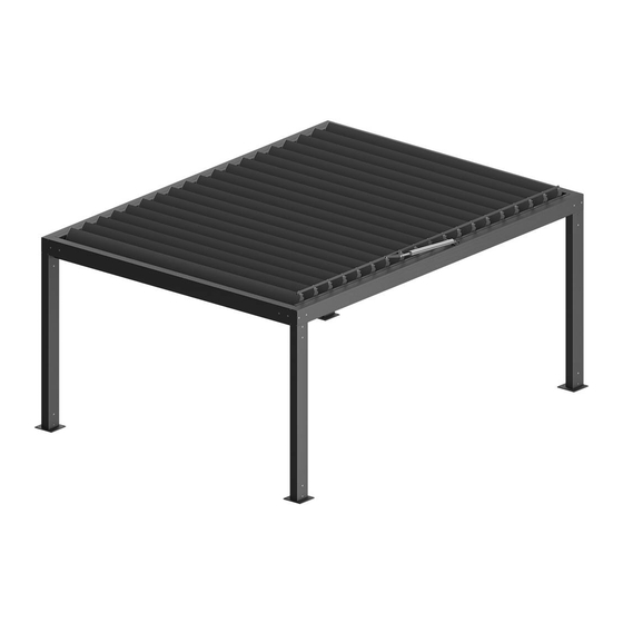
PRODUCT TECHNICAL IN FORMATION Technical specifications of the product are available on the website www.selt.com after logging in TECHNICAL PARAMETERS: SOLID SUNBREAKER Pergola - standalone Fig. 1. Standalone SOLID SUNBREAKER Pergola - Overall dimensions: B max – maximum width, L max – maximum length, H max –... - Page 8 The intermediate column can be placed in other distance, but it should not be larger than 5.2 m from the front or rear column. SOLID SUNBREAKER Pergola – modular Fig. 3. Modular SOLID SUNBREAKER Pergola - Overall dimensions: B – system width, B1 max - maximum width of single module, L max –...
- Page 9 Detailed data for parameters of the individual motors are available on the websites of motor manufacturers and on the website: www.selt.com→ PRODUCTS → CONTROL ENGINEERING DT-E 5.3: ALUMINIUM STRUCTURE – SOLID SUNBREAKER PERGOLA SYSTEM Revision 1 / March 2018 / PL...
-
Page 10: Product Specification
PRODUCT SPECIFICATIO N Products manufactured by SELT Sp. z o.o. distinguish with great technical and utility parameters. List of product types: standalone or standalone with the intermediate column, modular or modular with the intermediate column, installed outside... -
Page 11: Transport And Storage Of The Products
COMPLETENESS AND QUALITY CONDITION OF TH E DELIVERY SELT Sp. z o.o. makes every effort to ensure the conformity of the goods with the order. However, checking of product completeness should be done by the Purchaser and take place when it is received. -
Page 12: Product Assembly
This chapter contains general requirements concerning the product assembly. Correct assembly is a necessary condition for smooth operation of the product. SELT Sp. o.o. recommend using only professional assembly crews, which guarantee the Purchaser that the conducted installation will be correct. -
Page 13: Assembly Tools
SELT shall not be responsible for damages caused by the use of too weak anchoring components or fixing in the floor with too small load-bearing capacity, ... -
Page 14: Assembly
rope for protections / hoisting / removal of components, torque wrench. ASSEMBLY DT-E 5.3: ALUMINIUM STRUCTURE – SOLID SUNBREAKER PERGOLA SYSTEM Revision 1 / March 2018 / PL page 14 / 56... - Page 15 Fig. 6. View of assembly of the SOLID SUNBREAKER Pergola components. DT-E 5.3: ALUMINIUM STRUCTURE – SOLID SUNBREAKER PERGOLA SYSTEM Revision 1 / March 2018 / PL page 15 / 56...
- Page 16 Fig. 7. View of assembly of the components of SOLID SUNBREAKER Pergola with intermediate column. DT-E 5.3: ALUMINIUM STRUCTURE – SOLID SUNBREAKER PERGOLA SYSTEM Revision 1 / March 2018 / PL page 16 / 56...
- Page 17 Fig. 8. View of assembly of the SOLID SUNBREAKER Pergola modules. DT-E 5.3: ALUMINIUM STRUCTURE – SOLID SUNBREAKER PERGOLA SYSTEM Revision 1 / March 2018 / PL page 17 / 56...
-
Page 18: Pergola Assembly
Fig. 9. View of the assembly of the modules of SOLID SUNBREAKER Pergola with the intermediate column. Note: Prior to the assembly, you should check the visual condition of the components packaging delivered for assembly, the visual condition of the components and their completeness. The carrier shall be responsible for damages occurring during transport. -
Page 19: Assembly Of Support Structure For Single Version
4.6.1.1 ASSEMBLY OF SUPPORT STRUCTURE FOR SINGLE VERSION 1. Install front footing to a front column in accordance with the figure 1 and 2). NOTE: Front column is available in left and right version. Figure 1 and 2 presents column in left version. In case of assembly in the corner, you should use front modular footing as presented on figure 27, but you should use footing in R or L execution, depending on the... - Page 20 NOTE: Footing of the rear and intermediate column can be available in A and B type. Figure 5 3. Assemble left front column, rear column and intermediate column (if available) to left side beam. In accordance with figures Figure 6 4.
- Page 21 6. Place intermediate column of the fastener of left side beam, and then screw the column down to the fastener. NOTE: This operation should be executed when there is an intermediate column in the system, if not - the operation should be omitted. Figure 9 7.
- Page 22 10. Place intermediate column on fastener of right side beam, and then screw the column down to the fastener. NOTE: This operation should be executed when there is an intermediate column in the system, if not - the operation should be omitted. Figure 13 11.
- Page 23 Disassembly and assembly of guide for left side beam. Figure 17 12. Disassemble guide of left side beam by unscrewing screws fixing the guide prior starting the assembly of front beam. 13. Place front beam on fastener of left side beam and then screw the front beam to the fastener.
- Page 24 Disassembly and assembly of guide for right side beam. Figure 21 17. Disassemble guide from the right beam by unscrewing screws fixing the guide prior starting the assembly of the right side of the structure. 18. At the same time, place front and rear beam on fasteners of right side beam and then screw the front and rear beam to these fasteners as presented on the figures 26 and 27.
-
Page 25: Assembly Of Support Structure For Modular Version
4.6.1.2 ASSEMBLY OF SUPPORT STRUCTURE FOR MODULAR VERSION 1. Install front footing to a front column in accordance with the figure 25 and 26). NOTE: Front column is available in left and right version. Figure 25 and 26 presents column in left version. Figure 25 NOTE: Front footing is versatile and can be used for columns in left or right version. - Page 26 2. Install modular front footing to a front modular column accordance with figure and 33). NOTE: Front column is available in left and right version. Figure 28 and 29 presents column in left version. Figure 28 Figure 29 3. Install modular rear footing to the modular rear column and intermediate columns (if available) in accordance with the figure 30 and 31.
- Page 27 NOTE: Modular footing, rear, type A is versatile and can be used for columns in left or right version. Figure 32 NOTE: Modular footing, rear, type B is available in version L - left and R - right. Figure 33 4.
- Page 28 6. Place rear column of the fastener of left side beam, and then screw the column down to the fastener. Figure 36 7. Place intermediate column of the fastener of the left side beam and then screw the column down to the fastener. NOTE: This operation should be executed when there is an intermediate column in the system, if not - the operation should be omitted.
- Page 29 10. Place rear column of the fastener of right side beam, and then screw the column down to the fastener. Figure 40 11. Place intermediate column on fastener of right side beam, and then screw the column down to the fastener. NOTE: This operation should be executed when there is an intermediate column in the system, if not - the operation should be omitted.
- Page 30 14. Place left rear modular column on fastener of the left side modular beam and then screw the column down to the fastener. Figure 44 15. Place left intermediate modular column on fastener of the left side modular beam and then screw the column down to the fastener.
- Page 31 18. Place rear right modular column on fastener of the right side modular beam and then screw the column down to the fastener. Figure 48 19. Place right intermediate column on fastener of the right side modular beam and then screw the column down to the fastener.
- Page 32 View of front beam. Figure 51 View of rear beam. Figure 52 Disassembly of guide for left side beam. Figure 53 21. Disassemble guide of left side beam by unscrewing screws fixing the guide prior starting the assembly of front beam. NOTE: Disassembled guide...
- Page 33 23. Place rear beam on fastener of the left side beam and then screw the rear beam to the fastener. Figure 55 24. The complete right side of the structure should be placed next to the remaining part of the structure (use version of the component in accordance with the variant assembled...
- Page 34 Figure 59 27. Prior anchoring the module to the floor it is necessary to check the correctness of diagonals of the structure and vertical horizontal trueness structure components - make corrections of structure settings if necessary. 28. Anchor the structure to the ground after checking the setting of the module.
- Page 35 NOTE: Pay special attention to the alignment of the beams and columns of joined modules and concentricity of opening intended for structure screwing. NOTE: Pay attention to strips of EPDM foam glued to the lengthwise modular beam, to avoid its damage during assembly.
- Page 36 Figure 77 Assembly of driving guide of side beam. Figure 78 Assembly of driving guide of side beam. Figure 79 35. Successive modules should be installed to the already assembled structure by repeating operations from 30 to 36. Install the blades when the assembly of all modules is completed.
-
Page 37: Blades Assembly
4.6.1.3 BLADES ASSEMBLY NOTE: For convenience, it is recommended to start blades assembly from the extreme left module (when the system is viewed from the front while the motor is located on the right side beam). Then, start assembly of the blades in the module on the right side and proceed with blades assembly in the modules right. -
Page 38: Drive Assembly
2. Install pin of the blade driving side in the groove of the driving guide. Picture 4 3. Move the blade maximally closer on side of the driving guide. Picture 5 4. Click spacing clip on the pin of bearing side of the blade. Repeat steps 1 to 4 for the other blades. - Page 39 1. Disassemble screws from the handle of wrapping connector. Picture 8 2. Install sleeves on drive plug of the blade, repeat operation for all blades. Picture 9 3. Insert two threaded plates 13x13 to wrapping connector and set it opposite to the opening in the connector. Picture 10 4.
- Page 40 5. Screw down the blade to wrapping connector. NOTE: Tighten the screw until there is noticeable resistance. Picture 12 6. Installed handle of wrapping connector to the wrapping connector and screw together both components using the washer and self-locking screw M8. Picture 13 7.
- Page 41 11. Insert threaded plates 13x13 (for the remaining blades) to wrapping connector and set it opposite to the given blade. Picture 16 NOTE: Blades should be installed to the guide individually, from centre of the system to outside. Incorrect setting of the blades can result in incorrect operation of the system or its damage. 12.
-
Page 42: Gutters Assembly
15. Set the blade in a vertical position (open position) using a bubble level. NOTE: inaccuracy during blades setting should not exceed ±0.2°. Picture 20 16. Screw down the blade clamping screw to wrapping connector. Repeat steps 12 to 16 for the other blades. NOTE: Tighten the screw until there is noticeable resistance. -
Page 43: Electric Drive
2. Screw left gutter to left side beam using delivered sheet metal screws ST4.8. 3. Install overflow drain from gutter to front column after installation of the gutter to side beam. NOTE: Overflow should be placed in the opening of gutter and column using silicone sealant and sealant excess should be removed. -
Page 44: Start-Up And Adjustment
PRODUCTS → CONTROL ENGINEERING Environmental conditions with increased safety risks: environments with increased safety risks include: bathrooms, showers, kitchens, garages, basements, saunas, rooms for pet animals, operating suites in hospitals, pressure boosting stations, heat exchanger plants, spaces limited by conducting surfaces, campings, open areas etc. -
Page 45: System Operation And Product Safety
GENERAL REQUIREMENTS FOR OCCUPATIONAL HEALTH AND SAFETY To ensure correct operation of the product SELT Sp. z o.o. forbids making any structural changes; non-observance of the above condition releases the manufacturer from the liability for the product and the warranty will be invalidated. -
Page 46: Operational Safety
SELT service, DT-E 5.3: ALUMINIUM STRUCTURE –... -
Page 47: Connection To Electrical Installation
It is recommended to use wind control system helping to meet the safety conditions. If any abnormalities in product operation are detected then you should immediately inform the SELT Sp. o.o. service. Using damaged product and self-repairs pose a hazard for health and life and could be a reason of warranty invalidation... -
Page 48: Control
The manuals are enclosed to the product and they are also available on the websites of the motors manufacturers and on the website: www.selt.com→ PRODUCTS → CONTROL ENGINEERING The erroneous connection of the motor can lead to damage to the product or pose a threat. - Page 49 In case of defect, it is recommended stop further operation of the product. The defect should be reported to the supplier / fitter of the system. Stop operation of the product in case of wear and tear symptoms or damages of electric cables and immediately report your remarks to direct supplier.
-
Page 50: Use And Maintenance Of The System
Use of the product in accordance with the manufacturer recommendations ensure long-term and trouble-free operation of the system. If the product is used in the other way than described in this documentation or modified without the authorization of SELT o.o. -
Page 51: Technical Inspections, Maintenance And Repair
To ensure the safety of users and maximally long, correct operation of all mechanism the product should be subject to periodic inspections at least every 12 months. It is recommended to carry out periodic inspection of the product by the SELT Sp. z o.o. service The inspections are carried out as pay service. -
Page 52: Maintenance Operations
checking the correctness of operation of the limit switches, cleaning of visible, available components of the product (in particular, gutters on beams, mobile roof surface and rainwater effluents in footing of the front columns). Cleaning of metal/aluminium components: ... -
Page 53: General Warranty Conditions
Atmospheric and phytosanitary pollution and contamination caused by the animals. Damages caused by the influence of the other products, objects or suspended accessories not foreseen by SELT. Lack of water resistance resulting from location, type of finishing, installation and sealing as well as extreme weather have an essential influence on waterproofness of the product. -
Page 54: Complaint / Technical Defects
SELT Sp. z o.o. in Opole. complaints can be sent to electronic mail reklamacje@selt.com or directly to the sales representative. Notifications of technical defects / complaints shall be filed in writing using a form “zgłoszenie reklamacyjne/complaints”... -
Page 55: Dismantling / Disposal / Liquidation Of The Product
DISMANTLING / DISPOS AL / LIQUIDATION OF THE PRODUCT Incorrect disassembly of the system may lead to heavy bodily injuries and lead to system damages. System disassembly should be commissioned to properly qualified fitters team with adequate training within the scope of Occupational Health and Safety and knowledge within the scope of recycling. Disposal of Waste Electrical and Electronic Equipment When the service life of the product is over it is necessary to disassemble it for disposal and to sort the individual materials and components in compliance with the Regulation of the Minister of the Environment of 9 December 2014 on wastes... -
Page 56: Marking And Labelling Of The Product With Ce Mark
CONFORMITY OF PRODUC T WITH THE CE STANDARD SOLID SUNBREAKER pergola manufactured by SELT Sp. z o.o. meets the essential requirements of the standard introduced for steel and aluminium structures by the Polish Committee for Standardization (PKN) as PN-EN 1090-1 to PN-EN 1090-3, what is confirmed in the manufacturer declaration of performance and marking the product with CE mark.
Need help?
Do you have a question about the Pergola SB400 and is the answer not in the manual?
Questions and answers