SELT PERGOLA SB400 Installation Manual
Hide thumbs
Also See for PERGOLA SB400:
- Operation and maintenance manual (56 pages) ,
- Installation manual (64 pages)

Related Manuals for SELT PERGOLA SB400


Summary of Contents for SELT PERGOLA SB400
- Page 1 DT-E TECHNICAL AND OPERATIONAL DOCUMENTATION INSTALLATION MANUAL OPERATING MANUAL AND INSTRUCTIONS FOR SAFE USE 5. Steel and aluminium components and structural sets 5.8. Pergola SB400 (2020)
- Page 2 PRODUCT NAME: ALUMINIUM CONSTRUCTION PERGOLA SB400 (2020) MARKING OF PRODUCT MANUFACTURER: Manufacturer name: SELT Sp. z o. o. Manufacturer’s registered office: 45- 449 Opole, ul. Wschodnia 23A Contact details: Tel: +48 77 553 21 00 (secretariat) Fax: +48 77 553 22 00 ...
-
Page 3: Table Of Contents
TABLE OF CONTENTS INTRODUCTION ................................4 SAFETY GUIDELINES FOR THE PRODUCT......................... 4 EXPLANATION OF SYMBOLS AND SIGNS ......................... 4 TERMS AND DEFINITIONS ............................5 SUBJECT, INTENDED USE AND CONTENTS OF THE DOCUMENTATION ..............5 PRODUCT TECHNICAL INFORMATION .......................... 7 TECHNICAL PARAMETERS: ............................ -
Page 4: Introduction
INTRODUCTION SAFETY GUIDELINES FO R THE PRODUCT. The product has been manufactured in accordance with the latest technical knowledge in the field of construction and manufacturing and meets the safety requirements in accordance with the following standards. Subject European Legal Basis Polish Legal Basis Execution of steel and aluminium structures... -
Page 5: Terms And Definitions
For the purposes of this documentation the following terms and definitions shall apply: Product: PERGOLA SB400 Pergola SB400 system is made of powder-coated aluminium profiles and stainless components. Roof framework made of movable aluminium blades. The angle of inclination of the blades can be changed. Product design is offered in colour from RAL colour chart after confirmation of their availability by the manufacturer. - Page 6 SELT Sp. z o.o. shall not be responsible for damages resulting from non-observance of the recommendations included in this documentation. For further improvement of the product, SELT Sp. z o.o. reserves the right to introduce changes, which, while maintaining significant technical parameters, will be considered as appropriate for increasing the quality of product operation and safety of use.
-
Page 7: Product Technical Information
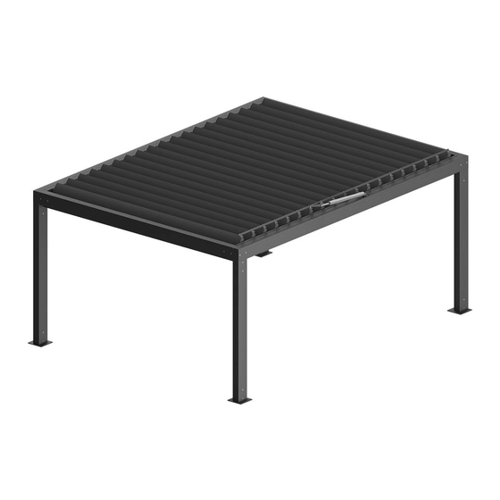
Pergola SB400 – free-standing Fig. 1. Pergola SB400 free-standing – Overall dimensions: B max – maximum width, L max – maximum projection, H max – maximum frame height (3012 mm), H1 max – maximum height of the clearance, H2 max – maximum height of position of the mechanism intended to change the angle of the blades (~3140 mm). - Page 8 Detailed data for parameters of the individual motors are available on the websites of motor manufacturers and on the website: www.selt.com→ PRODUCTS→ MOTOR, ELECTRIC, EQUIPMENT DT-E 5.8: ALUMINIUM CONSTRUCTION –PERGOLA SYSTEM SB400 (2020) Edition 2 / June 2020 / EN...
-
Page 9: Product Specification
PRODUCT SPECIFICATIO N Products manufactured by SELT Sp. z o.o. have excellent technical and functional parameters. List of product types: free-standing, modular, installed outside the building, started by electromechanical drive connected with the control system. They have the following features: ... -
Page 10: Transport And Storage Of The Product
COMPLETENESS AND QUALITY CONDITION OF DE LIVERY SELT Sp. z o.o. makes every effort to ensure the conformity of the goods with the order. However, checking of product completeness should be done by the Purchaser and should take place when it is received. -
Page 11: Product Installation
This chapter contains general requirements concerning the product installation. Correct assembly is a necessary condition for smooth operation of the product. SELT Sp. o.o. recommends using only professional assembly crews, which guarantee the Purchaser that the conducted installation will be correct. -
Page 12: Preparation For Installation
Walls or floor should be load-bearing and adapted for transferring of forces from product anchoring. SELT shall not be responsible for damages caused by use of too weak anchoring components or fixing in the floor with too small load bearing. -
Page 13: Installation Tools
INSTALLATION TOOLS Installation instructions, operation and maintenance manual and instructions for safe use are available at www.selt.com after logging in. List: drill bits for metal and concrete, hammer drill, ladder / scaffolding, crane, bucket truck, loader crane, ... -
Page 14: Installation
INSTALLATION Fig. 4a. View of the assembly of elements of free-standing Pergola SB400 DT-E 5.8: ALUMINIUM CONSTRUCTION –PERGOLA SYSTEM SB400 (2020) Edition 2 / June 2020 / EN strona 14 / 42... - Page 15 Fig. 4b. View of the assembly of elements of wall-mounted Pergola SB400. DT-E 5.8: ALUMINIUM CONSTRUCTION –PERGOLA SYSTEM SB400 (2020) Edition 2 / June 2020 / EN strona 15 / 42...
- Page 16 Fig. 5. View of the assembly of modular Pergola SB400. DT-E 5.8: ALUMINIUM CONSTRUCTION –PERGOLA SYSTEM SB400 (2020) Edition 2 / June 2020 / EN strona 16 / 42...
-
Page 17: Pergola Installation
4.6.1 PERGOLA INSTALLATION Fig. 6. Marking of the types of feet (view from above) of Pergola SB400. Foot A Foot B Foot C Foot D/F Foot E Foot G Foot H Foot I Fig. 7. Type of foot for Pergola SB400. -
Page 18: Installation Of The Support Structure
4.6.1.1 INSTALLATION OF THE SUPPORT STRUCTURE 1. Place all beam elements on their correct sides and posts in their correct corners. 2. Front beam (fig. 2) has a side-mounted sheet metal gutter. Place it with the gutter facing the inside of the pergola. - Page 19 5. Assemble selected side beam (with holes for blades) with two fitting posts by inserting the sockets of the posts into the ends of the beam (large chamber). Fix it at the top ends of the beam with countersunk screws with M8x20 Allen socket (fig.
- Page 20 NOTE: In case of visible uneveness of the beam and post edges (fig. 7a) it can be corrected by: - checking if the diagonals of pergola are identical and, if needed, correcting the position of the base of the foot - removing the beam from the socket/bone, loosening M8 screws securing the socket/bone in the post and using a hammer to move the protruding end of the...
-
Page 21: Installation Of The Gutters
Figure 10 14. To connect pergola SB400 modules with each other, countersunk nuts and threaded studs are used (fig. 11), and in the beams coaxial through holes with deepening are made. - Page 22 1. Determine the position of individual gutters in accordance with the layout of overflow openings in the beams. Start the installation of gutters on both side beams (with openings for blades). 2. The back surface of the gutter adjacent to the beams should be carefully sealed with silicone (delivered with the product).
-
Page 23: Installation Of The Blades
NOTE: During the first heavy rainfall, it is recommended to visually inspect the contact points which are sensitive to leakage and, in the event of noticed leaks, fill the seals with silicone. Such places include: the joints of the gutters with the beams, contact points of the side beam gutters with front/rear beam gutters, the lower edges of the gutters under the side oval drains, places for fixing screws of wall brackets with beams, the connection of the bent gutters in the rear beam. - Page 24 4. Insert sequentially blades to the beams: place them horizontally above pergola (drive side of the beam with motor), insert the end without the snap-ring into the hole in the beam until it stops, then lower and insert the other end of the blade (with the ring) until the snap-ring rests against the beam.
-
Page 25: Installation Of The Drive
NOTE: Before installing the rod, motor should have the piston completely hidden (it is delivered like this by SELT). When inserting the pin, there is a risk of the slip ring being forced out. A dedicated ring insertion tool is recommended. - Page 26 5. Install the drive rod to other blades. Place the hole of the blade’s drive end cap to the hole in the rod by rotation movement. Press the bracket’s pin into the joint from the blade side (reverse direction is also allowed), until the second groove appears on the other side (farther from the end).
-
Page 27: Wall Installation
4.6.2 WALL INSTALLATION Wall installation is carried out with the use of wall brackets located at the points specified by the Manufacturer. The fastening element of pergola can be: the rear beam of the roof the side beam of the roof. A –... -
Page 28: Wall Installation Lengthwise Beam
Table 1 Maximum forces * Along axis X 0,48 kN Along axis Y 0,63 kN Along axis Z 5,3 kN * - Forces in the plane of the holes 12.4 mm (see fig. 33). Given force values in Table 1 refer to forces for a single wall bracket. 1. - Page 29 Table 2 Maximum forces* Along axis X 0,86 kN Along axis Y 0,17 kN Along axis Z 6.84 kN * - Forces in the plane of the holes 12.4 mm (see fig. 33). Given force values in Table 2 refer to forces for a single wall bracket. Wall installation –...
-
Page 30: Electric Drive
These instructions are added with the product; they are also available on the website of motor manufacturers and on website: www.selt.com → PRODUCTS → MOTOR, ELECTRIC, EQUIPMENT NOTE: Risk of damaging the limit switches due to exceeding the permitted adjustment range. See point 4.6.1.4. -
Page 31: Start-Up And Adjustment
Environmental conditions with increased safety risks: environments with increased safety risks include: bathrooms, showers, kitchens, garages, basements, saunas, rooms for pet animals, operating suites in hospitals, pressure boosting stations, heat exchanger plants, spaces limited by conducting surfaces, campings, open areas etc. In rooms and spaces, where there are increased safety risks it is appropriate to use automatic devices shutting down the supply of damaged product, e.g. -
Page 32: System Operation And Product Safety
The roof should be open in case of snowfall. Pergola SB400 should not be used, and you should not stay under it, during storm, hail, heavy snowfall, heavy rain (roof should be left opened). No obstacles (e.g. cables, branches, leaves) should be present in blades area during their rotation. -
Page 33: Operational Safety
SELT service, ... -
Page 34: Connection To Electrical Installation
CONNECTION TO ELE CTRICAL INSTALLATION When the Pergola SB400 is assembled one should proceed to connection of drive and control system to the previously prepared systems: electrical supply installation and control system. -
Page 35: Control
The manuals are enclosed to the product and they are also available on the websites of the motors manufacturers and on the website: www.selt.com → PRODUCTS → MOTOR, ELECTRIC, EQUIPMENT The erroneous connection of the motor can lead to damage to the product or pose a threat... - Page 36 Remote control should be kept away from children. The work area of the pergola SB400: crushing, cutting and pulling in hazard Do not touch mobile components during closing or opening of the mobile roof. It can be a reason of crushing, cutting, pulling in, trapping between e.g.
-
Page 37: System Use And Maintenance
If the product is used in other way than described in this documentation or modified without the authorization of SELT Sp. z o.o. then this is considered as misuse. -
Page 38: Basic Operations Carried Out During Periodic Inspection
The inspections are carried out as pay service. Inspections are based on checking of product operation, adjustment of mechanisms and replacement of consumables. 6.3.1 BASIC OPERATIONS CAR RIED OUT DURING PERIODIC INSPECTION . List: checking of fixing of the product to the ground/wall, ... -
Page 39: Maintenance Operations
To check or maintain electrical equipment the sunshade should be disconnected safely from the power source. MAINTENANCE OPERATIO NS To ensure correct operation of the Pergola SB400 system it is appropriate to maintain components of the drive system (sleeves, screws, bearings) using grease or other preservation agents). -
Page 40: Complaint / Technical Defects
SELT Sp. z o.o. in Opole, complaints can be sent to electronic mail reklamacje@selt.com or directly to the sales representative. Notifications of technical defects / complaints shall be filed in writing using a form “Complaint” available on the website www.selt.com/dokumenty-en or directly to sales representative. -
Page 41: Product Disassembly / Utilisation / Disposal
PRODUCT DISASSEMBLY / UTILISATION / DISPOSAL Incorrect disassembly of the system may lead to heavy bodily injuries and lead to system damages. System disassembly should be commissioned to properly qualified installers team with adequate training within the scope of Occupational Health and Safety and knowledge within the scope of recycling . Disposal of Waste Electrical and Electronic Equipment When the service life of the product is over it is necessary to disassemble it for disposal and to sort the individual materials and components in compliance with the Regulation of the Minister of the Environment of 9 December 2014 on wastes... -
Page 42: Marking And Labelling The Product With The Ce Mark
PRODUCT COMPLIANCE W ITH THE CE STANDARD Pergola SB400 manufactured by SELT Sp. z o.o. meets the essential requirements of the standard introduced for steel and aluminium structures by the Polish Committee for Standardization (PKN) as PN-EN 1090-1 to PN-EN 1090-3, what is confirmed in the manufacturer declaration of performance and marking the product with CE mark.
Need help?
Do you have a question about the PERGOLA SB400 and is the answer not in the manual?
Questions and answers