
Related Manuals for Jäger ADwin-Gold-USB


Summary of Contents for Jäger ADwin-Gold-USB
- Page 1 ADwin-Gold- USB / -ENET Manual ADwin-Gold USB / ENET, manual version 3.8, October 2005...
- Page 2 For any questions, please don’t hesitate to contact us: Hotline: +49 6251 96320 Fax: +49 6251 5 68 19 Jäger Computergesteuerte E-Mail: info@ADwin.de Messtechnik GmbH Rheinstraße 2-4 Internet www.ADwin.de D-64653 Lorsch Germany ADwin-Gold USB / ENET, manual version 3.8, October 2005...
-
Page 3: Table Of Contents
ADwin Table of contents Typographical Conventions ..........IV 1 Information about this Manual . -
Page 4: Typographical Conventions
ADwin Typographical Conventions Typographical Conventions "Warning" stands for information, which indicate damages of hardware or soft- ware, test setup or injury to persons caused by incorrect handling. You find a "note" next to – information, which have absolutely to be considered in order to guaran- tee an operation without any errors –... -
Page 5: Information About This Manual
ADwin Information about this Manual 1 Information about this Manual This manual contains complex information about the operation of the ADwin- Gold system. Additional information are available in – the manual "ADwin Driver Installation", which describes all interface installations for the ADwin systems. With this manual you begin your installation! –... -
Page 6: System Description
ADwin System description 2 System description 2.1 ADwin system concept ADwin systems guarantee fast and accurate operation of measurement data acquisition and automation tasks under real-time conditions. This offers an ideal basis for applications such as: – very fast digital closed-loop control systems –... - Page 7 ADwin System description Communication between ADwin system and PC The ADwin system is connected to the PC via an USB or Ethernet interface. Interfaces After power-up the ADwin system is booted from the PC via this interface. Afterwards the ADwin operating system is waiting for instructions from the PC which it will process.
-
Page 8: The Adwin-Gold System
ADwin System description 2.2 The ADwin-Gold System Processor and memory The ADwin-Gold system is equipped with the digital 32 bit signal processor T9 (SHARC ADSP 21062) from Analog Devices with floating point and integer processing. It is responsible for the complete measurement data acquisition, online processing, and signal output, and makes it possible to process instan- taneously sample rates of up to several 100 kHz. - Page 9 ADwin System description The standard delivery items for the ADwin-Gold system: Standard delivery – the ADwin-Gold system with USB or Ethernet interface, – a USB cable or a cross-over Ethernet cable from the PC to the Gold device (length about 1.8m). –...
-
Page 10: Operating Environment
ADwin Operating Environment 3 Operating Environment The ADwin-Gold electronic is installed in a closed aluminum enclosure and it is only allowed to operate it in this enclosure. With the necessary accessories the system can be operated in 19-inch-enclosures or as a mobile system (e.g. in cars). -
Page 11: Initialization Of The Hardware
ADwin Initialization of the Hardware 4 Initialization of the Hardware If you start initializing do not connect any cables to the ADwin-Gold before you have executed the following steps: – Carry out completely the installation of the drivers and the power supply at the computer or notebook (see manual: "ADwin Driver Installation"). - Page 12 ADwin Initialization of the Hardware Booting Start ADbasic and boot the ADwin system by clicking on the "Boot button" The display in the status line: "ADwin is booted" shows that the operating system has been loaded appropriately and that via ADbasic the ADwin sys- tem has been connected.
-
Page 13: Inputs And Outputs
ADwin Inputs and Outputs 5 Inputs and Outputs All inputs and outputs may only be operated according to the specifications Connectors given (see Annex A.1 Technical Data). In case of doubt, ask the manufacturer of the device, to which you want to connect the ADwin-Gold system. Open-ended inputs can cause errors - above all in an environment where inter- ferences may occur. -
Page 14: Analog Inputs And Outputs
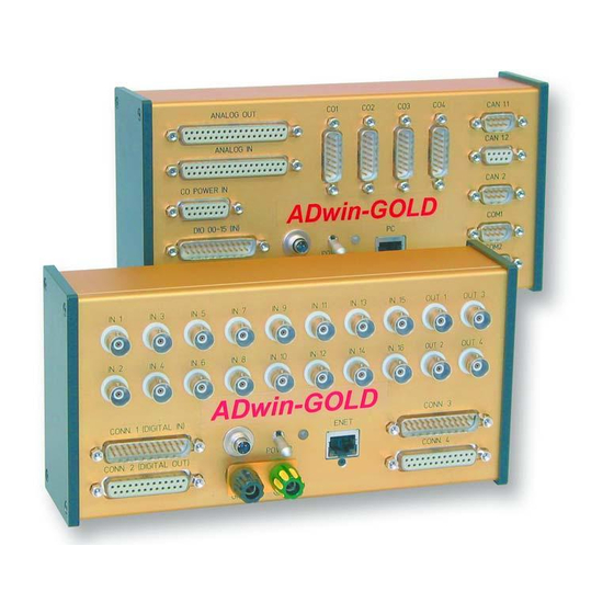
ADwin Inputs and Outputs analog additional inputs/outputs inputs/outputs ANALOG OUT CAN 1.1 ANALOG IN CAN 1.2 CO POWER IN CAN 2 ADwin- Gold DIO 00-15 (IN) COM1 POWER DIO 16-31 (OUT) COM2 digital GND/PE power- ENET inputs/outputs connector supply connector Fig. - Page 15 ADwin Inputs and Outputs ANALOG IN ANALOG OUT (female) (male) Fig. 6 – Pin assignment of analog channels with Gold-D option 5.1.1 Analog Inputs The system has 16 analog inputs IN1 … IN16. The inputs with odd numbers (1, Multiplexer 3, …...
- Page 16 ADwin Inputs and Outputs Please pay attention to a low internal resistance of the power supply unit (of the input signals), because it may have influence on the measuring accuracy. If this is not possible: – Depending on the output resistance a linear error is caused. You can compensate this by multiplying the measurement value with a corresponding factor and get a sort of recalibration.
- Page 17 ADwin Inputs and Outputs In the bipolar setting you will get a zero offset, also called offset U in the fol- Zero offset U lowing text. For the voltage range of −10V … +10V applies: = −10V The ADwin-Gold has a programmable gain (PGA), with which you can amplify Gain factor k the input voltage by the factors 1, 2, 4, and 8.
-
Page 18: Digital Inputs And Outputs
ADwin Inputs and Outputs Tolerance Ranges Slight variations regarding the calculated values may be within the tolerance range of the individual component. Two kinds of variations are possible (in LSB), which are indicated in this hardware manual: – The integral non-linearity (INL) defines the maximum deviation from the ideal straight line over the whole input voltage range. - Page 19 ADwin Inputs and Outputs Contrary to the standard instructions ADC(), ADC12() and DAC() the instruc- tions for direct access do not have any test routines. Before you use them we recommend to learn more about time sequences, program structures and func- tions sequences in an ADC.
- Page 20 ADwin Inputs and Outputs Address Function Commentary [HEX] 31:16 15:10 9 8 7 6 5 4 3 2 1 0 ""nnn"" binary = 0...7 decimal, Set MUX 1: channels 1, 3, 5, …, 15 n n n selected ch. = nnn + ""nnn""...
- Page 21 ADwin Inputs and Outputs 5.3.2 Digital Inputs and Outputs After power-up of the device all 4 connection groups are configured as inputs; this corresponds to the instruction CONF_DIO(0). The following table shows how the inputs and outputs (IN, OUT) are configured when you use the value of the first column as instruction argument.
-
Page 22: Calibration
ADwin Calibration 6 Calibration 6.1 General Information The 2 digital-to-analog (DAC, optional 8) and the 4 analog-to-digital (ADC) converters of the ADwin-Gold systems have been calibrated in factory. In accordance with the regulations for keeping the measurement accuracy in your field of application, the systems must be calibrated in regular time inter- vals. - Page 23 ADwin Calibration The upper field shows the current measurement values at the inputs IN1 and IN2, measured each by the 16-bit and the 14-bit ADC. Select in the lower field left the DAC which you wish to calibrate and at right the ADC.
- Page 24 ADwin Calibration Connect a DMM to the selected out- Connect the voltage source (or a put. calibrated DAC output) to the selected input. Please note Fig. 4 "Schematic of ADwin-Gold (USB version)". Select "Next Step >>". 2. Setting the offset Adjust the offset value at the scroll- Set your voltage source to 0 V.The bar in such a manner that your digi-...
- Page 25 ADwin Calibration The program outputs the values 0...65535 digits on both DACs, compares them to the measured input values and displays the deviation in graphs. The deviation should be less than 5 digits. With Close you return to the overview window. With "Print Calibration"...
-
Page 26: Add-On
ADwin DA Add-On 7 DA Add-On Connectors With the DA add-on you will get 6 additional analog outputs with a resolution of 16 bit (and a DAC each). In the standard version two of these outputs go from DAC 3 and DAC 4 to the BNC plugs OUT 3 and OUT 4. -
Page 27: Co1 Counter Add-On
ADwin CO1 Counter Add-On 8 CO1 Counter Add-On The technical data of the counter add-on CO1 is described in the annex A.1. 8.1 Hardware The counter add-on CO1 (ordering option Gold-CO1) has four 32-bit up/down Counter counters with four-edge-evaluation. You can configure and read out the counters individually as well as all together. - Page 28 ADwin CO1 Counter Add-On You can calculate: 1. the period duration of the input signal at CLR/LATCH from the values in latch A or latch B. 2. the pulse width and pause time from the values in latch A and latch B The counters are controlled by ADbasic instructions via a control register (instructions, see table in chapter 8.2).
-
Page 29: Software
ADwin CO1 Counter Add-On On the option Gold-D you can – via the connector CO Power in – supply a volt- age, which is then available at the connectors CO1…CO4, e. g. for external Inkrementalgeber. Please note: All minus inputs V1 (-) are galvanically connected to GND via a common line;... - Page 30 ADwin CO1 Counter Add-On For further processing of the values in the ADbasic program, transfer the val- ues into the latch register and read them out there. Please pay attention to the fact that the CNT_SET instruction depends on the CNT_MODE instruction.
-
Page 31: Operating Mode Impulse/Event Counting
ADwin CO1 Counter Add-On 8.3 Operating Mode Impulse/Event Counting External square-wave signals at the inputs A/CLK and B/DIR clock the counters in this mode. With CNT_SET you either activate the mode for determining the clock frequency and direction or the four edge evaluation. The input CLR/LATCH (at high-signal) can be used to –... - Page 32 ADwin CO1 Counter Add-On 8.3.2 Four Edge Evaluation This mode determines clock and direction of two signals, which are phase- shifted by 90 degrees to the inputs A and B. The count direction is determined by the temporal sequence of the rising and falling edges of the two input sig- nals.
-
Page 33: Operating Mode Impulse Width And Period Width Measurement
ADwin CO1 Counter Add-On 8.4 Operating Mode Impulse Width and Period Width Measurement In this operating mode an internal reference clock generator clocks the counter Reference clock with a signal frequency of 20 MHz or (after a prescaler) 5 MHz. All counters generator have a switch in order to change the signal frequency. - Page 34 ADwin CO1 Counter Add-On 8.4.2 Impulse Width and Pause Duration Measurements All 4 counters measure impulse width and pause duration. 32 bit Latch A LATCH Data ref.-CLK switch Divider ÷ 4 32 bit Counter 20 MHz to f switches of other counters 32 bit Latch B Data...
- Page 35 ADwin CO1 Counter Add-On 8.4.3 Hardware addresses (CO1-add-on) A process can be executed very quickly if you access directly the control and data register (see chapter 5.3 and ADbasic manual). The hardware addresses of the CO1 add-on can be found in the following table (see command index table in chapter 8.2).
-
Page 36: Can Add-On
ADwin CAN add-on 9 CAN add-on The add-on Gold-CAN is equipped with several additional interfaces that are configured and operated individually: – 4 SSI decoders (page 33) The decoders can be used for the connection of incremental encoders with SSI interface. All inputs are differential and designed for RS422/485 level (5V). -
Page 37: Ssi Decoder
ADwin CAN add-on 9.1 SSI Decoder An incremental encoder with SSI interface can be connected to the decoders. The signals are differential and have RS422/485 levels. The decoders either read out an individual value (on request) or they conti- nously provide the current value. The connections of the 4 decoders are on the connectors CO1...CO4 (15-pin, DSUB), on the pins 5, 8, 14 and 15 (see fig. - Page 38 ADwin CAN add-on Example: A conversion from Gray code into binary code is made with the routine below, Conversion of which you have programmed in the ADbasic process. Gray code REM PAR_1 = Gray value to be converted REM PAR_2 = Flag indicating a new Gray value REM PAR_9 = Result of the Gray-to-binary conversion AS LONG EVENT:...
-
Page 39: Can Interface
ADwin CAN add-on 9.2 CAN Interface The CAN interfaces 1 and 2 can be operated individually. Depending on your requirements, you can order both interfaces either as high-speed or low-speed version. Switching in operation is not possible. 9.2.1 Hardware Description The connections of the interfaces 1 and 2 are located on the 9-pin DSUB con- nector: –... - Page 40 ADwin CAN add-on 9.2.2 Description of the CAN interface ® The CAN bus interface is equipped with the Intel CAN controller AN82527 which works according to the specification CAN 2.0 parts A and B as well as to ISO 11898. You program the interface with ADbasic instructions, which are directly accessing the controller’s registers.
- Page 41 ADwin CAN add-on An arriving message overwrites the old data in the message object, which will be definitely lost. Therefore pay attention to reading out the data faster than you are receiving them. A data loss is indicated by a flag. The message object 15 has an additional buffer, so that 2 messages can be stored there.
- Page 42 ADwin CAN add-on The following table shows the admitted values and the meaning of the individ- ual ranges: Range Admitted Meaning values 0 … 3 Max. pulse elongation during bus synchronization 0 … 63 Pre-scaler 0 … 1 Sampling mode TSEG1 2 …...
-
Page 43: Rsxxx Interfaces
ADwin CAN add-on Range Instructions Receiving and sending of data CAN_MSG EN_RECEIVE EN_TRANSMIT READ_MSG TRANSMIT Write / read access to the SET_CAN_REG controller register GET_CAN_REG The instructions are in the include file <ADWGCAN.INC>. More information can also be found in the ADbasic manual and the online help. 9.3 RSxxx Interfaces Each of the 2 RSxxx interfaces is equipped with the "Quad Universal Asynchro- nous Receiver/Transmitter"... - Page 44 ADwin CAN add-on Parity – Parity: In order to recognize an error or incorrect data during the transfer, a parity bit can be transferred at the same time. The parity can be even or odd or you can have no parity bit at all. Data bits –...
- Page 45 ADwin CAN add-on Example programs The following program illustrates the initialization of the serial RS232 interface RS232 in the INIT: section and the cyclic reading and writing of data in the EVENT:. section. The process is timer-controlled: REM The program initializes the serial interface REM in the Init: section.
- Page 46 ADwin CAN add-on RS485 In this example the RS485 interface is a passive participant, which reads data coming from the input. If a specified value (55) is received, the interface starts to send. It sends continuously the value 44. REM Interface 2 reads all data coming from the bus REM until it receives the value 55.
-
Page 47: Adwin-Gold-Boot
ADwin ADwin-Gold-Boot 10 ADwin-Gold-Boot This option is only available in an ADwin-Gold-ENET. ADwin-Gold-Boot starts a previously programmed application automatically after power-up. After installation of this application an operation without com- puter is possible. With ADwin-Gold-Boot the following steps are executed after power-up: –... -
Page 48: Accessories
ADwin Accessories 11 Accessories The following accessories are available for the ADwin-Gold: – ADwin-Gold-pow: external 12V power supply unit – various lengths of power supply and USB or Ethernet cable – cable connector for an external power supply – mounting kits for enclosures ADwin-Gold-pow On the secondary side ADwin-Gold-pow provides 12 Volt at a maximum load of 2 Ampere. -
Page 49: Annex
ADwin Annex Annex A.1 Technical Data All technical data refer to a powered-up ADwin-Gold system. General Data/Limit Values Symbol Conditions min. typ. max. Unit Supply Voltage/Supply Current Voltage =10V =12V Idle current, =35V idle, USB USB Interface =12V; Gold-DA =12V; Gold-CO1 =12V Power-up current, =12V;... - Page 50 ADwin Annex Digital Inputs/Outputs Parameters Symbol Conditions min. typ. max. Unit I/O-lines DIO00:DIO31 32 (programmable in groups of 8 as inputs or outputs) Number EVENT ext. trigger input (positive TTL logic) Inputs = 5V Max. input voltage -0.5 +5.5 (High) = 5V Logic input voltage...
- Page 51 ADwin Annex Analog Inputs/Outputs Parameters Symbol Conditions min. typ. max. Unit Drift ±2 ppm/K Offset Error adjustable Drift ±5 ppm/K Gain Error adjustable ADC 16-bit Conversion time µs conv +9.999695 +4.999847 Measurement range -2.5 +2.499924 -1.25 +1.249962 Diff. common mode voltage ±2.5 Integral non-linearity ±1...
- Page 52 ADwin Annex CO1 Add-On Parameters Symbol Conditions min. typ. max. Unit Counter Number 4 counters (CNTR1 … CNTR4) For each counter 3 differential inputs (A/CLK, B/DIR, CLR/LATCH); counter inputs Inputs programmable in pairs for differential or TTL mode (single-ended) Counter resolution Input CLK Count frequency Input A/B...
-
Page 53: Hardware Addresses - General Overview
ADwin Annex A.2 Hardware Addresses - General Overview Address Register available Function Bit No.. Comment [HEX] in the module Gold- Gold- 31:16 15:10 9 8 7 6 5 4 3 2 1 0 Gold "nnn"binary = 0…7 decimal, Set MUX 1: IN1, IN3, …, IN15 - - - - - - - n n n selected channel = nnn + 1 "nnn"... - Page 54 ADwin Annex Address Register available Function Bit No.. Comment [HEX] in the module Gold- Gold- 31:16 15:10 9 8 7 6 5 4 3 2 1 0 Gold Write into register and start conver- 20400240 x x x x x x x x x x –...
-
Page 55: Hardware Revisions
ADwin Annex A.3 Hardware revisions The revision of a Gold system is marked on the bottom of the casing. The dif- ferences of the revision status’ are shown below. First Revision Changes to previous revision status release 1998 First release with link data connection. Nov. -
Page 56: Table Of Figures
ADwin Annex A.4 Table of figures Fig. 1 – Concept of the ADwin systems ......3 Fig. -
Page 57: Index
ADwin Annex A.5 Index block diagram · 4 Gain factor k · 13 Boot automatic · 43 impulse width measurement · 29 from ADbasic · 8 Inputs Bus frequency CAN, see CAN bus analog, voltage range · 12 digital · 14 Calibration ·...
Need help?
Do you have a question about the ADwin-Gold-USB and is the answer not in the manual?
Questions and answers