Table of Contents
Advertisement
Quick Links
Advertisement
Table of Contents

Related Manuals for Jäger ADwin-Gold


Summary of Contents for Jäger ADwin-Gold
- Page 1 ADwin-Gold Hardware Manual Version 2.3 November 2002...
- Page 2 ADwin ADwin-Gold Hardware Manual, Version 2.3...
-
Page 3: Table Of Contents
1. Information about this Manual ........................5 2. ADwin System Features ..........................6 2.1 System Concept ........................... 6 2.2 The ADwin-Gold System ........................8 3. Operating Environment ..........................10 4. Initialization of the Hardware ........................11 5. Inputs and Outputs ............................ 12 5.1 Analog Inputs and Outputs ......................... -
Page 4: Typographical Conventions
Program instructions and inputs in the editor window are characterized by the value 1 font Courier New Names of variables in examples are printed in italics Var_1 Typography for ADbasic instructions (in capital letters) ENTER ADwin-Gold Hardware Manual, Version 2.3... -
Page 5: Information About This Manual
– the manual: „ADbasic“, which contains all instructions for the compiler ADbasic. With this easy-to-learn real-time development tool you can initialize your ADwin-Gold optimally for your control processes or for your control or measurement tasks. Please pay attention to the following information Please pay attention to the information given in this documentation and in other mentioned manuals so that the ADwin system works appropriately. -
Page 6: Adwin System Features
Distinctive features The ADwin-Gold system is equipped with analog and digital inputs and outputs, a fast processor (32 bit floating point signal processor) and a local RAM. The processor is responsible for the whole real-time processing in the system. The applications are running independent of the PC and its workload. -
Page 7: Figure 2-1: Concept Of The Adwin-Systems
Windows programs can access the same ADwin system at the same time. This is of course a great advantage when programs are developed and installed. Figure 2-1: Concept of the ADwin Systems ADwin-Gold Hardware Manual, Version 2.3... -
Page 8: The Adwin-Gold System
These two outputs are optionally converted by a 12-bit or 16-bit analog-to-digital converter (ADC), (see Figure: Bock diagram ADwin-Gold ). With the 12-bit ADCs it is possible to sample very fast with the 16-bit ADCs highly accurately. - Page 9 PC or notebook to the ADwin-Gold. The ADlink cable transfers data from the ADlink ISA board to the ADwin-Gold. It has 9-pin D-Sub connectors and it is shielded on both ends. If requested we will deliver an ADlink cable which is shielded on one end (optically isolated).
-
Page 10: Operating Environment
The ADwin-Gold is operated with a protection low voltage of 10 to 18 Volts and is not life-threatening. For operation with an external power supply, the instructions of the manufacturer applies. -
Page 11: Initialization Of The Hardware
4. Initialization of the Hardware 4. Initialization of the Hardware If you start initializing do not connect any cables to the ADwin-Gold before you have executed the following steps: – carry out the driver installation at the PC or notebook (see manual „ADwin Driver Installation“). -
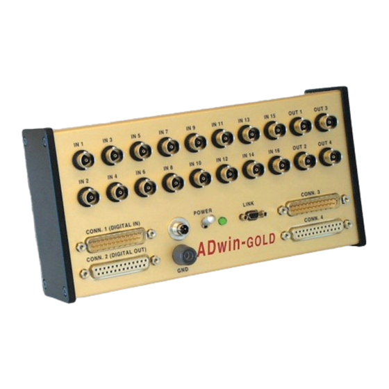
Page 12: Inputs And Outputs
All inputs and outputs may only be operated according to the specifications given (s. annex A-1 „Technical Data“). In case of doubt, ask the manufacturer of the device, to which you want to connect the ADwin-Gold system. Please avoid connecting and operating at the analog inputs when the ADwin- Gold system is switched off. -
Page 13: Figure 5-2: Power Supply Connector
+9...18V Figure 5-2: Power supply connector (male) If you operate the ADwin-Gold together with a PC, the system can get its power supply by using the power-connector of the link adapter. For using the system with an external power supply unit you need the subminia- ture connector described above of the series 712, with the article number: 2 99-0406-00-03. -
Page 14: Analog Inputs And Outputs
The power supply from the ADlink or ADlink-PCI board also connects the earth of the ADwin-Gold with the earth of the PC. If you do not operate the PC and the ADwin-Gold system in the same place, you should not use the power supplied by the PC but an external power supply unit which if fully earth-free, in order to avoid influences by different ground reference potentials. -
Page 15: Figure 5-3: Zero Offset In The Standard Setting Of Bipolar 10 Volt
If it is not in the value range the maximum (65,535) or minimum (0) value is output (see also ADbasic manual). 5.1.3 Calculation Basis The voltage range of the ADwin-Gold at the analog inputs and outputs is between –10 V to +10 V (bipolar 10 V). The 65,536 (2... - Page 16 The integral non-linearity (INL) defines the maximum deviation from the ide- al straight line of the conversion characteristics curve, covering the whole input voltage range. • The differential non-linearity (DNL) defines the maximum deviation from the ideal quantization level. ADwin-Gold Hardware Manual, Version 2.3...
-
Page 17: Figure 5-4: Jumper Position On The Analog Printed Circuit Board
At „single ended“ inputs all outer conductors of the BNC sockets are connected via jumper Jx with the common ground (GND-connection). The ADwin-Gold is delivered with the jumper setting for differential inputs, that Jumper (Jx) means the jumpers (Jx) are only plugged into one of the two pins. For the „single-ended“... -
Page 18: Digital Inputs And Outputs
Trigger input (EVENT) The ADwin-Gold is equipped with an external trigger input (EVENT). With this trigger input processes are triggered by an external signal (trigger) with rising edge and can completely and immediately be processed. (see ADbasic manual, chapter „Structure of an ADbasic-Program“). -
Page 19: Time-Critical Tasks
DAC registers with direct access to the hardware registers, and you can synchronously start the output (see ADbasic manual). The hardware addresses for the direct access to the control and data registers are described on the following pages. ADwin-Gold Hardware Manual, Version 2.3... - Page 20 ) t i t s i x x x x x x x x x x ) t i Table 5-1: Hardware addresses of the control and data registers for the ADC ADwin-Gold Hardware Manual, Version 2.3...
- Page 21 : y l e t i t s i x x x x x x x x x x : y l Table 5-2: Hardware addresses of the control and data registers for the DAC ADwin-Gold Hardware Manual, Version 2.3...
- Page 22 Table 5-3: Hardware addresses of the digital inputs/outputs ADwin-Gold Hardware Manual, Version 2.3...
-
Page 23: Calibration
The analog (printed circuit) board (see the following figure), is directly located below the front panel, below the front panel there is the digital (printed circuit) board with the ADSP. If the ADwin-Gold system is equipped with an add-on, this component will be located between the analog and digital (printed circuit) boards. -
Page 24: Initializing The Software
The values indicated in the programs refer to the voltage range of 20 Volt (-10V...+10V) of the ADwin-Gold at the analog inputs and outputs. Conversion of digits into Notes for the conversion of voltage into digits, digits into voltage as well as... -
Page 25: Adjustment
1 - 0 . . . t i b 1 - 0 V t i b µ ; t i µ t i b Table 6-1: Test values for the adjustment of the DACs/ADCs ADwin-Gold Hardware Manual, Version 2.3... -
Page 26: Processes For Calibration
The ADbasic processes for calibration can be found as <*.bas>-files on the ADwin-CD-ROM beginning from version 3.00.30xx in the directory <C:\ADwin\Tools\Calibration\...>. 1. Output voltage with the DAC (Process 1) 'Process for the ADwin-Gold in order to 'output a voltage with the 16 bit DAC. 'Last modification on July 31st, 2000 'Usage of the variables: 'PAR_10: DAC channel number (1 or 2, with DA add-on: 1...8) - Page 27 ADwin 6.5 Processes for Calibration 3. Read voltage with the 12-bit ADC (Process 3) 'Process for the ADwin-Gold in order to 'read a voltage with a 12 bit ADC. 'A mean value is calculated in FPAR_2. 'Last modification on August 08...
-
Page 28: Add-On
Buffer DAC-7 & -8 ALS14 FPGA P24 P23 GAIN P18 P17 P20 P19 P22 P21 GAIN GAIN GAIN GAIN GAIN DAC-8 DAC-3 DAC-4 DAC-5 DAC-6 DAC-7 Figure 7-2: Position of the trimmers for calibration (DA add-on) ADwin-Gold Hardware Manual, Version 2.3... -
Page 29: Opt Add-On
An optical isolation of the channels among each other is not possible. All digital Reference potential inputs and outputs have a common reference potential (OPT-GND). If you have purchased an ADwin-Gold system with OPT add-on, the digital Configuration inputs and outputs have to be configured by the instruction CONF_DIO(12), which sets DIO 0...15 as inputs and DIO 16...31 as outputs. -
Page 30: Digital Inputs
Depending on the output current I and the connected V (=Vcc) the transistor causes a voltage drop between 0.7 and 1.2 Volt. An inverse diode protects the transistor during switching of an inductive load against overvoltage. ADwin-Gold Hardware Manual, Version 2.3... - Page 31 = 5 V = 2 V = 4 V µ = 5 V = 2 V l l a = 4 V i l p l l a Table 8-1: Technical data of the OPT add-on ADwin-Gold Hardware Manual, Version 2.3...
-
Page 32: Co1 Counter Add-On
– the period duration of the input signal at CLR/LATCH from the values in latch A or latch B. – the impulse width and pause time from the values in latch A and latch B (only counters 1 and 2). ADwin-Gold Hardware Manual, Version 2.3... -
Page 33: Software
1 1 1 1 0 0 0 0 1 1 1 1 0 0 0 0 & 1 1 1 1 . . . r t ( . . . r t ( l l a ADwin-Gold Hardware Manual, Version 2.3... - Page 34 The count direction (up or down) can reliably be derived from the sign of the difference: [new counter value] minus [old counter value] and not from the comparison of the counter values. Calculate the difference only with integer variables (INTEGER, LONG). ADwin-Gold Hardware Manual, Version 2.3...
- Page 35 Such a lap overflow occurs after some 3½ minutes with an input frequency of 20 MHz or after more than 14 minutes with 5 MHz. You will find several example programs for the CO1 add-on in the directory Example programs <C:\ADwin\ ADbasic 3\samples_ADwin_Gold> (Standard installation). ADwin-Gold Hardware Manual, Version 2.3...
-
Page 36: Mode Impulse/Event Counting
CLR/LATCH to CLR mode CNT_INPUTMODE(0) enable counter CNT_ENABLE(1) . . . EVENT: latch current counter values to latch registerA CNT_LATCH(1) read out latch register A CNT_READLATCH(1) evaluate counter values in program . . . ADwin-Gold Hardware Manual, Version 2.3... - Page 37 CLR/LATCH to CLR mode CNT_INPUTMODE(0) enable counter CNT_ENABLE(1) . . . EVENT: latch current counter values to latch register A CNT_LATCH(1) read out latch register A CNT_READLATCH(1) evaluate counter values in program . . . ADwin-Gold Hardware Manual, Version 2.3...
-
Page 38: Mode Pulse Width And Period Width Measurement
... with 20 MHz or CNT_SET(0) ... with 5 MHz CNT_SET(1) set input CLR/LATCH to LATCH-mode CNT_INPUTMODE(1) enable counter CNT_ENABLE(1) . . . EVENT: read out latch register A CNT_READLATCH(1) evaluate counter values in program . . . ADwin-Gold Hardware Manual, Version 2.3... - Page 39 ... with 5 MHz CNT_SET(1) set input CLR/LATCH to LATCH-mode CNT_INPUTMODE(1) enable counter CNT_ENABLE(1) . . . EVENT: read out latch register A CNT_READLATCH(1) read out latch register B CNT_READFLATCH(1) evaluate counter values in program . . . ADwin-Gold Hardware Manual, Version 2.3...
-
Page 40: Hardware Addresses (Co1 Add-On)
- t i n = 5 V t i n = 5 V c t i µ l i c t a l t f i Table 9-3: Technical data of the CO1 add-on ADwin-Gold Hardware Manual, Version 2.3... -
Page 41: Co1 Add-On With Opto-Couplers
9.7 CO1 Add-on with opto-couplers 9.7 CO1 Add-On with opto-couplers If your ADwin-Gold system is equipped with an OPT add-on, then the inputs of the CO1 add-on have also opto-couplers. The notes given in the chapter 8: „OPT add-on“ apply also for the CO1 add-on. -
Page 42: Adwin-Gold-Boot
ADwin-Gold-Boot starts a previously programmed application, automatically after power-up. After installation of this application an operation without PC is possible. With ADwin-Gold-Boot the following steps are executed after power-up: – Loading the operating system – Loading the processes built with the ADbasic compiler (max. 10) –... -
Page 43: Accessories
– various power supply and link cables – cable connector for an external power supply On the secondary side ADwin-Gold-pow provides 12 Volt at a maximum load ADwin-Gold-pow of 2 Ampere. The power supply unit is rated for the highest load and maximum expansions of the ADwin-Gold. -
Page 44: Annex
ADwin Annex Annex A-1 Technical Data - General Overview All technical data refer to a powered-up ADwin-Gold system. i L / . n i t i n a t l a t l = 0 V = 2 V = 8 V... - Page 45 ± n i l y t i ± ± n i l y t i ± ± t f i ± ° / s f f t f i ± ° / ADwin-Gold Hardware Manual, Version 2.3...
- Page 46 - c = 5 V ± ± µ = 6 A a t l o l ( = 6 A ± ± ™ . n i t i n ™ t s i . . . ADwin-Gold Hardware Manual, Version 2.3...
-
Page 47: Hardware Addresses - General Overview
) t i x x x x x x 0 0 0 0 x x x x x x x x x x x x x x x x x x x x ADwin-Gold Hardware Manual, Version 2.3... - Page 48 - x x x x . t x - x x x x . t n i f e r o i t ; . l o i t - x x x x = x 5 ADwin-Gold Hardware Manual, Version 2.3...
-
Page 49: List Of Common Abbreviations
MB Multiplexer OpAmp Operational amplifier Personal computer Programmable gain amplifier S&H Sample & Hold SRAM Static random access memory Transistor-transistor logic Voltage collector-collector Voltage emitter-emitter Up/Down Manufacturers Analog Devices Burr-Brown Linear Technology Texas Instruments ADwin-Gold Hardware Manual, Version 2.3... -
Page 50: List Of Figures
Table of Figures A-4 List of Figures Figure 2-1: Concept of the ADwin-systems ....................7 Figure 2-2: Block diagram ADwin-Gold ......................8 Figure 5-1: Schematic of ADwin-Gold ......................12 Figure 5-2: Power supply connector ......................13 Figure 5-3: Zero offset in the standard setting of bipolar 10 Volt ..............15 Figure 5-4: Jumper position on the analog printed circuit board ..............
Need help?
Do you have a question about the ADwin-Gold and is the answer not in the manual?
Questions and answers