Motorola solutions ST7500 User Manual
Portable two-way radios
Hide thumbs
Also See for ST7500:
- Product information manual (108 pages) ,
- Basic service manual (104 pages)

Subscribe to Our Youtube Channel
Related Manuals for Motorola solutions ST7500


Summary of Contents for Motorola solutions ST7500
- Page 1 Mobile Release 2021.2 ST7500 Feature User Guide JULY 2021 *MN004519A01* MN004519A01-AL © 2021 Motorola Solutions, Inc. All rights reserved...
-
Page 2: Table Of Contents
2.2.7 Removing the Battery....................25 2.2.8 Charging the Battery....................26 2.2.9 Battery Charging Indications..................26 2.2.10 Low Battery Indication....................27 2.3 ST7500 Controls and Indicators.................... 27 2.4 Powering On the Radio......................30 2.5 Writing Text..........................30 2.5.1 Text Entry Icons....................... 30 2.5.2 Keys Usage......................31 2.6 PIN Code Authentication....................... - Page 3 MN004519A01-AL Contents 2.9 Holding Your Radio........................36 2.10 High or Low Audio Toggle....................37 2.10.1 Using High Audio....................37 2.10.2 Using Low Audio....................38 2.11 During a Call........................38 2.12 Selecting Talkgroups......................38 2.13 Entering TMO or DMO Mode....................38 2.14 Covert Solution........................39 2.14.1 Sending Mission Critical Communication Tones............39 2.15 Over The Air Programming....................40 2.16 One-Touch Buttons......................41...
- Page 4 MN004519A01-AL Contents 3.3.10 Gateway and Repeater Synchronization............... 51 3.4 Transmit Inhibit Mode......................51 3.5 Emergency Operations......................52 3.5.1 Emergency Alarm....................52 3.5.2 Emergency Group Call.....................52 3.5.2.1 Making Emergency Group Calls..............53 3.5.2.2 Receiving Emergency Group Calls............53 3.5.3 Non-Tactical Emergency..................53 3.5.4 Emergency Individual Calls (Private or MSISDN)............53 3.5.5 Emergency SDS Status...................
- Page 5 MN004519A01-AL Contents 4.4.4.2 Responding to Call-Out Messages............66 4.4.5 Templates........................ 66 4.4.5.1 Sending User-Defined Templates.............. 66 4.4.5.2 Managing User-Defined Templates............67 4.4.6 Predefined Templates....................67 4.4.6.1 Viewing Predefined Templates..............67 4.4.6.2 Sending Predefined Templates..............67 4.4.7 Status Messages..................... 68 4.4.7.1 Viewing a Status Message Number............68 4.4.7.2 Sending Status Messages.................
- Page 6 MN004519A01-AL Contents 4.9 Man Down..........................78 4.9.1 Setting Man Down....................78 4.10 Scan.............................78 4.10.1 Enabling Talkgroup Scanning................79 4.10.2 Activating Talkgroup Scanning................79 4.10.3 Viewing Scan Lists....................79 4.10.4 Renaming Scan List....................79 4.10.5 Clearing Scan List....................80 4.10.6 Adding Group to Scan List..................80 4.10.7 Editing Talkgroup....................
- Page 7 MN004519A01-AL Contents 4.12.6 Accessory (Accry) Setup..................88 4.12.7 Default Setting....................... 88 4.12.7.1 Selecting Default Setting................88 4.13 My Info..........................88 4.13.1 Viewing Personal Information................88 4.13.2 Viewing Talkgroup Subaddresses................. 89 4.14 Recent Calls........................89 4.14.1 Viewing Recent Calls..................... 89 4.14.2 Calling from Recent Calls..................89 4.14.3 Deleting Recent Calls....................
- Page 8 MN004519A01-AL Contents 5.7 Individual Call........................101 5.7.1 Private Call......................102 5.7.2 Phone and PABX Calls..................102 5.7.3 Receiving Individual Calls..................102 5.8 SIM Card End-to-End Encryption..................102 5.9 Terminal Permanent Disable....................103 5.10 Terminal Temporary Disable or Enable................103 Appendix A: Tones....................104 Appendix B: LED Indications................106 Appendix C: Troubleshooting................107 Appendix D: Maintenance..................
-
Page 9: List Of Figures
Figure 9: Closing the SIM Connector Door ....................22 Figure 10: Closing the SIM/microSD Door .................... 22 Figure 11: Charger Mode Screen ......................27 Figure 12: ST7500 Controls and Indicators ...................28 Figure 13: Default Home Screen with Icons ..................33 Figure 14: RCU Tone Button ......................... 40 Figure 15: Trunked Mode Operation ..................... -
Page 10: List Of Tables
Table 1: Special Notations ........................14 Table 2: Product Technical Information ....................15 Table 3: Battery Icons ..........................27 Table 4: ST7500 Controls and Indicators ....................28 Table 5: Text Entry Screen Icons ......................30 Table 6: Keys Usage ..........................31 Table 7: PIN Code Authentication Icons ....................31 Table 8: Display .............................33... -
Page 11: Safety Information
Exposure and Product Safety Guide for Portable Two-Way Radios which contains important operating instructions for safe usage and RF energy awareness and control for Compliance with applicable standards and Regulations. For a list of Motorola Solutions-approved antennas, batteries, and other accessories, visit the following website: http://www.motorolasolutions.com Under Industry Canada regulations, this radio transmitter may only operate using an antenna of a type and maximum (or lesser) gain approved for the transmitter by Industry Canada. -
Page 12: Applying For Canadian License
Applying for Canadian License Applying for Canadian License The operation of your Motorola Solutions radio is subject to the Radio communications Act and must comply with rules and regulations of the Federal Government's department of Industry Canada. Industry Canada requires that all operators using Private Land Mobile frequencies obtain a radio license before operating their equipment. -
Page 13: Copyrights
Motorola Solutions, Inc. Furthermore, the purchase of Motorola Solutions products shall not be deemed to grant either directly or by implication, estoppel or otherwise, any license under the copyrights, patents or patent applications of Motorola Solutions, except for the normal non-exclusive, royalty-free license to use that arises by operation of law in the sale of a product. -
Page 14: Chapter 1: General Information
MN004519A01-AL Chapter 1 : General Information Chapter 1 General Information Icon Conventions The documentation set is designed to give the reader more visual clues. The following graphic icons are used throughout the documentation set. DANGER: The signal word DANGER with the associated safety icon implies information that, if disregarded, will result in death or serious injury. -
Page 15: Chapter 2: Getting Started
MN004519A01-AL Getting Started Chapter 2 Getting Started Familiarize yourself with basic information on how to use the radio. Product Technical Information Table 2: Product Technical Information Description Value Maximum Voltage 4.2 V Maximum Current Maximum RF Power 1.8 W Maximum Speaker 4 Ω... -
Page 16: Replacing Antenna
MN004519A01-AL Chapter 2 : Getting Started 2.2.1 Replacing Antenna Procedure: 1 Remove the antenna by turning anti-clockwise. 2 Replace the new antenna by insert the screw-in base of the antenna into the antenna terminal on the top of the radio. 3 Turn clockwise until tight. - Page 17 MN004519A01-AL Chapter 2 : Getting Started 2 Lift the battery cover using the Battery Cover Finger Scoop. 3 Remove the battery cover completely from the radio. To attach the battery cover: NOTE: Ensure that the Battery Cover Latch is at the Unlock position before attaching the battery cover.
-
Page 18: Installing The Sim Card
MN004519A01-AL Chapter 2 : Getting Started 5 Press the top part of the battery cover down followed by the middle part of the battery cover. 6 Lock the battery cover by sliding the Battery Cover Latch to the left. 2.2.3 Installing the SIM Card Prerequisites: Ensure that your radio is either MicroSD card-enabled or SIM card-enabled. -
Page 19: Figure 1: Opening The Sim/Microsd Door
MN004519A01-AL Chapter 2 : Getting Started Figure 1: Opening the SIM/microSD Door 3 Slide up and unlock the SIM connector door (as indicated by the arrow engraved on the SIM connector door). 4 Flip open the SIM connector door. Figure 2: Opening the SIM Connector Door 5 Insert the SIM card into the SIM connector slot, ensuring that the gold contact area is facing down. -
Page 20: Removing The Sim Card
MN004519A01-AL Chapter 2 : Getting Started Figure 4: Closing the SIM Connector Door 7 Close the SIM/microSD door. Figure 5: Closing the SIM/microSD Door IMPORTANT: Ensure that the latch on the SIM/microSD door is locked in place before placing the battery into the radio. 8 Install the battery and attach the battery cover. -
Page 21: Figure 6: Opening The Sim/Microsd Door
MN004519A01-AL Chapter 2 : Getting Started Figure 6: Opening the SIM/microSD Door 3 Slide up and unlock the SIM connector door (as indicated by the arrow engraved on the SIM connector door). 4 Flip open the SIM connector door. Figure 7: Opening the SIM Connector Door 5 Remove the SIM card from the SIM connector slot. -
Page 22: Micro Cryptr Card
MN004519A01-AL Chapter 2 : Getting Started Figure 9: Closing the SIM Connector Door 7 Close the SIM/microSD door. Figure 10: Closing the SIM/microSD Door IMPORTANT: Ensure that the latch on the SIM/microSD door is locked in place before placing the battery into the radio. 8 Install the battery and attach the battery cover. - Page 23 MN004519A01-AL Chapter 2 : Getting Started 3 Slide to unlock the microSD card holder as indicated by the marking engraved on the microSD card holder. 4 Flip open the microSD card holder. 5 Carefully insert the micro CRYPTR card into the microSD card holder ensuring that the gold contact area is facing down.
-
Page 24: Removing The Micro Cryptr Card
MN004519A01-AL Chapter 2 : Getting Started IMPORTANT: Please ensure that the latches on the metal cover door is locked in place before placing the battery into the radio. 8 Install the battery. 2.2.5.2 Removing the Micro CRYPTR Card Procedure: 1 Remove the battery. 2 Flip open the metal cover door of the radio. -
Page 25: Removing The Battery
MN004519A01-AL Chapter 2 : Getting Started 2 Press the battery downward until it clicks. 2.2.7 Removing the Battery Prerequisites:Turn off the radio. Procedure: 1 Pull the clip upwards. The battery pops up. 2 Lift out the battery. -
Page 26: Charging The Battery
You can charge a battery separately or attached to a radio. IMPORTANT: Use only Motorola Solutions approved-chargers which provide optimal performance. Using other chargers may fail to fully charge, or reduce the life of the battery. Do not charge the battery in a hazardous area. -
Page 27: Low Battery Indication
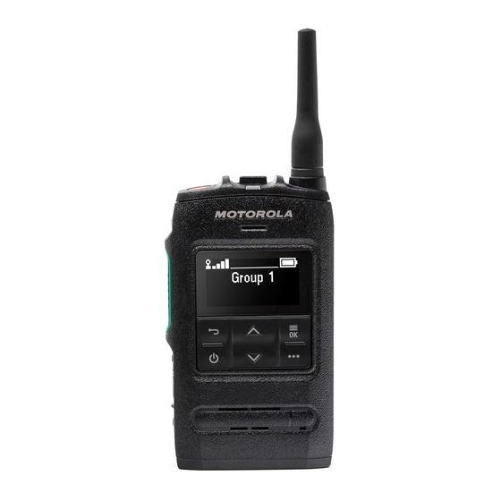
The pop-up message is also shown when the battery level is at 20 % or lower upon radio power-up. ST7500 Controls and Indicators The simple-to-use controls and indicators of ST7500 allow you to quickly read and respond to alerts received on the radio. -
Page 28: Figure 12: St7500 Controls And Indicators
MN004519A01-AL Chapter 2 : Getting Started Figure 12: ST7500 Controls and Indicators Table 4: ST7500 Controls and Indicators Annotation Description Talkgroup Selector The Talkgroup Selector has the following functions: • Turns on the display when toggled once. Subsequent toggling allows you to scroll through the talkgroups of the current selected folder on the Idle screen. - Page 29 MN004519A01-AL Chapter 2 : Getting Started Annotation Description Push-to-Talk (PTT) button Used to initiate a simplex call. NOTE: Pressing PTT activates the display for three seconds. Volume button Increases or decreases the volume by pressing + or -. P2 Programmable Button Supports the One-Touch Button feature.
-
Page 30: Powering On The Radio
MN004519A01-AL Chapter 2 : Getting Started Annotation Description Earpiece The Earpiece is active during low-audio simplex or duplex calls. Hybrid Antenna Battery Cover Finger Scoop Battery Cover Latch Used to lock or unlock the battery cover. Battery Cover Seal Label IMPORTANT: Do not remove the seal label to avoid compromising the in- gress protection of IP67. -
Page 31: Keys Usage
MN004519A01-AL Chapter 2 : Getting Started 2.5.2 Keys Usage Table 6: Keys Usage Description Up navigation button Press to scroll through the letters, numbers, or symbols. Down navigation button Press to scroll through the letters, numbers, or symbols. Back button •... -
Page 32: Unlocking Your Radio
MN004519A01-AL Chapter 2 : Getting Started Icon Description Enter New Code Prompts for new PIN code entry when PIN code change is selected. Re-Enter New Code Prompts for a repeat of the new PIN code entry when PIN code change is selected. -
Page 33: Configurable Idle Screen
MN004519A01-AL Chapter 2 : Getting Started Figure 13: Default Home Screen with Icons Test Group Table 8: Display Annotation Description Status icon area Text display area 2.7.1 Configurable Idle Screen Your service provider can configure the information that is displayed on the idle screen below the status icon area. -
Page 34: Table 10: Direct Mode Operation (Dmo) Icons
MN004519A01-AL Chapter 2 : Getting Started Table 10: Direct Mode Operation (DMO) Icons Icon Description Direct Mode Call Radio is receiving a Direct Mode call. The more bars, the stronger the signal. Direct Mode Radio is in Direct Mode, radio-to-radio communication. DMO Gateway Communication Mode Indicates that the gateway is selected. - Page 35 MN004519A01-AL Chapter 2 : Getting Started Icon Description Man Down Alert Indicates that the Man Down feature is active. This icon has the following states: Blinking (Pre-Alert State) Triggered to inform and check on your status to avoid false Man Down trigger.
-
Page 36: Holding Your Radio
MN004519A01-AL Chapter 2 : Getting Started Icon Description Call-Out Alert Arrived Indicates a receipt of a new Call-Out message. Call-Out Alert Unread Indicates unread alert in the CO Box. End-to-End Encryption (E2EE) Solid, when E2EE is enabled: • For the selected talkgroup, •... -
Page 37: High Or Low Audio Toggle
MN004519A01-AL Chapter 2 : Getting Started Simplex Calls When using high audio, hold your radio a vertical position with its top microphone 5–10 cm away from your mouth. Speak into the top microphone. Listen through the internal speaker. Keep the antenna at least 2.5 cm from your head and body. -
Page 38: Using Low Audio
MN004519A01-AL Chapter 2 : Getting Started 2.10.2 Using Low Audio When and where to use:Placing or receiving a Phone, PABX, or Duplex Private call. NOTE: It can also be used in group mode when discrete listening is required. Procedure: 1 Hold your radio as you would a telephone. 2 Speak into the bottom microphone and listen through the earpiece. -
Page 39: Covert Solution
MN004519A01-AL Chapter 2 : Getting Started Procedure: 1 From the home screen, press the Menu/OK key. 2 Select Networks. 3 Select Trunked Mode/Direct Mode. NOTE: Changing talkgroups using the Talkgroup Selector button also changes the network mode accordingly for the selected talkgroup when in favorite folders. 2.14 Covert Solution NOTE: This is a Software Selling Feature. -
Page 40: Over The Air Programming
MN004519A01-AL Chapter 2 : Getting Started Figure 14: RCU Tone Button Description RCU Tone Button NOTE: The RCU is a small third-party device attached to your covert radio over a wire. 2.15 Over The Air Programming NOTE: This is a Software Selling Feature. Over The Air Programming (OTAP) enables remote radio reconfiguration over TETRA network. -
Page 41: One-Touch Buttons
MN004519A01-AL Chapter 2 : Getting Started 2.16 One-Touch Buttons The One-Touch Button (OTB) feature allows you to activate a feature by a long key press of the programmable button. Table 13: One-Touch Button Features Feature Description Activation of Covert Solu- Turns Covert Solution on or off. - Page 42 MN004519A01-AL Chapter 2 : Getting Started Feature Description After the timer expires, the radio returns to the previously selected talkgroup. TMO ↔ DMO Switch Toggles between TMO and DMO modes. TMO Talkgroup Scan Turns the Talkgroup Scan feature in TMO Mode on or off. Toggle Bluetooth Discov- Turns Discoverable Mode on or off.
-
Page 43: Chapter 3: Modes
MN004519A01-AL Modes Chapter 3 Modes This chapter contains information on available modes that the radio can operate in. Trunked Mode Operation Trunked Mode Operation (TMO) requires the switching and management infrastructure. TMO enables various voice and data communication types such as group calls. TMO also enables access to features related to infrastructure such as packet data. -
Page 44: Receiving Group Calls In Idle
MN004519A01-AL Chapter 3 : Modes 3.1.3 Receiving Group Calls in Idle Procedure: 1 Your radio receives a Group Call. NOTE: The incoming Group Call is signaled by a Receiving Group Call tone. 2 To respond, press and hold the PTT button. 3.1.4 Receiving Group Calls during Ongoing Group Calls While in active Group Call, your radio receives a Group Call with a higher priority.Your radio is forced... -
Page 45: Dgna Reception
MN004519A01-AL Chapter 3 : Modes • Add talkgroups. • Attach or select newly added talkgroups. • Delete talkgroups. • Modify parameters of existing talkgroups. All the above operations are performed by transmitting data to your radio. 3.1.6.1 DGNA Reception When a DGNA message is received, your radio plays a tone and displays a message Talkgroup list updated. -
Page 46: Phone And Pabx Calls
MN004519A01-AL Chapter 3 : Modes 3.1.8 Phone and PABX Calls Phone Calls allow you to call a landline telephone number or a cellular mobile phone number. Private Automatic Branch Exchange (PABX) Calls allow you to call local (office) extension numbers. NOTE: This feature is available only in Trunked Mode Operation (TMO). -
Page 47: Direct Mode Operation
MN004519A01-AL Chapter 3 : Modes Direct Mode Operation Direct Mode Operation (DMO) is a mode of simplex operation where radios communicate directly without the need of a network. NOTE: For those who use DMO mode, you are recommended to apply DMO SCK for data confidentiality. -
Page 48: D-Ptt Preempt Group Call
MN004519A01-AL Chapter 3 : Modes 2 To respond, press and hold the PTT button. 3.3.4 D-PTT Preempt Group Call NOTE: This is a Software Selling Feature. The D-PTT Preempt Group Call allows superiors to take over and speak in an ongoing group call by making preemptive priority calls. -
Page 49: Dmo Private Priority Call
MN004519A01-AL Chapter 3 : Modes • GW + Rep – Uses the first available gateway or repeater for that talkgroup. • Automatic – Uses the first available gateway for that talkgroup. • Specific – Uses only the Gateway with the specified Gateway address for that talkgroup. NOTE: When the Gateway and the Repeater cannot be communicated even though a talkgroup to use them is configured, the radio attempts the direct MS-MS communication. -
Page 50: Communication Through Gateways
MN004519A01-AL Chapter 3 : Modes Figure 17: Communication through Repeaters When the radio connects to a repeater, it plays a tone, displays the Repeater available message, and shows an appropriate icon. When the radio loses connection with the repeater, it plays a tone, displays the Repeater not available message, and the repeater icon is blinking. -
Page 51: Gateway And Repeater Synchronization
MN004519A01-AL Chapter 3 : Modes • Gateway not available message is displayed. • The gateway icon is blinking. 3.3.10 Gateway and Repeater Synchronization To communicate using gateways or repeaters, the radio requires synchronization with a gateway or a repeater. A gateway or a repeater sends presence signals to radios. If a radio receives presence signals, it stays synchronized with the gateway or the repeater which sends the signals. -
Page 52: Emergency Operations
MN004519A01-AL Chapter 3 : Modes In TXI mode, the radio joins group calls for any group that the radio is monitoring, but the transmitting on that call is still prohibited. If you initiate an emergency call, the radio immediately leaves TXI mode and attempts to start the emergency call if the radio is in service. -
Page 53: Making Emergency Group Calls
MN004519A01-AL Chapter 3 : Modes 3.5.2.1 Making Emergency Group Calls Prerequisites:Ensure that your radio is in Emergency Mode. Procedure: 1 Press and hold the PTT button. 2 Wait for the talk permit tone (if configured) and talk. 3 Release the PTT button to listen. NOTE: It is possible to cancel making an emergency group call in TMO. -
Page 54: Emergency Sds Status
MN004519A01-AL Chapter 3 : Modes 3.5.5 Emergency SDS Status The radio sends a status message with a preprogrammed value to the destination address set by your service provider. Emergency SDS Status is available in TMO only. If no status acknowledgment or negative acknowledgment is received, the radio retries sending the message. -
Page 55: Emergency Mode By Dialing
MN004519A01-AL Chapter 3 : Modes 3.5.9 Emergency Mode by Dialing This feature allows you to trigger Emergency Mode by dialing a predefined number. It initiates the same emergency services as when you use the Emergency button. Your radio can store up to eight emergency numbers. -
Page 56: Chapter 4: Main Menu
MN004519A01-AL Chapter 4 : Main Menu Chapter 4 Main Menu This chapter contains information on items in the main menu. IMPORTANT: Ensure the Menu Configuration is enabled on the CPS to allow the menu settings to be visible on the radio MMI. Scrolling through the Menu Procedure: 1 From the home screen, press the Menu/OK key. -
Page 57: Dialer
This menu item allows you to dial a number to initiate a private, phone, or Private Automatic Branch Exchange (PABX) call. You can also enter the dialing editor by pressing a pre-configured One-Touch Button. ST7500 Controls and Indicators on page 27 for the keys' functions to dial a number. Similar to the icons used in... -
Page 58: Making Phone Or Pabx Calls
MN004519A01-AL Chapter 4 : Main Menu 4 Depending on the mode, perform one of the following actions: If… Then… If you are making simplex calls in TMO or a Press the PTT button. DMO, b Wait for the Talk Permit tone before talk- ing. -
Page 59: New Message
MN004519A01-AL Chapter 4 : Main Menu 4.4.1 New Message This menu item allows you to create a new message. Writing Text on page 30 for text entry method on your radio. 4.4.1.1 Sending Messages to Private or Phone Procedure: 1 From the home screen, press the Menu/OK key. 2 Select Messages→New Message. -
Page 60: Delivery Report
MN004519A01-AL Chapter 4 : Main Menu 2 Select Messages→New Message. 3 Enter your message. 4 Press and hold the Menu/OK button. 5 Select Message Setup and choose one of the following options. • Online User • On/Offline Usr 6 Select Send. 7 Select one of the following options: •... - Page 61 MN004519A01-AL Chapter 4 : Main Menu If the radio receives the Delivery Report after a longer period, the radio saves the Delivery Report and a copy of the message in the Outbox. If the radio receives the Delivery Report after a longer period and your service provider configures the functionality of the Delivery Report Notifications, the radio displays the following results: •...
-
Page 62: Inbox
MN004519A01-AL Chapter 4 : Main Menu 4.4.2 Inbox The inbox folder contains up to 100 new or old incoming messages, depending on the length of the messages. The Messages sub-menu indicates the number of the messages. For example, if the indication is 2/4, it means that two unread and four read messages are in the inbox. - Page 63 MN004519A01-AL Chapter 4 : Main Menu 3 Select the required message and press the Menu/OK button. 4 If you want to use submenus, perform one of the following actions: If… Then… If you want to delete the message, perform the following actions: a Select Delete.
-
Page 64: Embedded Number
MN004519A01-AL Chapter 4 : Main Menu 4.4.2.4 Embedded Number The Embedded Number feature allows you to call a number embedded in the message in the Inbox or Outbox folder. You can also start a group call with the message sender of a talkgroup. 4.4.2.5 Calling Numbers from Messages The Embedded Number feature is enabled by your service provider. -
Page 65: Opening The Outbox
MN004519A01-AL Chapter 4 : Main Menu Icon Description Protected Message Delivery In Progress Protected Message Delivery Accomplished Protected Message Delivery Failed Encrypted Message Delivery In Progress Encrypted Message Delivery Accomplished Encrypted Message Delivery Failed Encrypted and Protected Message Delivery In Progress Encrypted and Protected Message Delivery Ac- complished... -
Page 66: Responding To Call-Out Messages
MN004519A01-AL Chapter 4 : Main Menu Icon Description Unread (New) Call-Out Message in Inbox Read (Old) Protected Call-Out Message in Inbox Unread (New) Protected Call-Out Message in Inbox Read (Old) Call-Out Message in Outbox Read (Old) Protected Call-Out Message in Outbox 4.4.4.2 Responding to Call-Out Messages When a Call-Out message is received and acknowledgment is required, you can response to the... -
Page 67: Managing User-Defined Templates
MN004519A01-AL Chapter 4 : Main Menu 2 Select Messages→Templates. 3 Select the required template. 4 Press the Menu/OK key and select Send. 5 Press and hold the Menu/OK key and select a contact. 6 Send the message by pressing the Menu/OK key. 4.4.5.2 Managing User-Defined Templates Procedure:... -
Page 68: Status Messages
MN004519A01-AL Chapter 4 : Main Menu If… Then… a Press the Menu/OK key and select Edit. NOTE: The edit screen opens with the template text. You are only allowed to replace the ex- isting text. b Press and hold the Menu/OK key to send the message. -
Page 69: Additional Address
MN004519A01-AL Chapter 4 : Main Menu By default, targeted status messages can be sent to private or talkgroup addresses. Your service provider can restrict valid addresses to numbers stored in Contacts. NOTE: This feature is not supported on Dimetra networks. 4.4.7.3.1 Sending Targeted Status Messages Procedure:... -
Page 70: Call-Out Availability
MN004519A01-AL Chapter 4 : Main Menu 4.4.9 Call-Out Availability NOTE: This feature is only available when enabled by your service provider. This menu item enables or disables the Call-Out availability. 4.4.9.1 Setting Call-Out Availability Procedure: 1 From the home screen, press the Menu/OK key. 2 Select Messages→Call-Out Availability. -
Page 71: Dialing Through The Contact List
MN004519A01-AL Chapter 4 : Main Menu Type Each contact is assigned to one of the following types: Table 19: Contact Types Contact Icon Description Private Mobile Home Work PABX Other # (number) Number for the contact pre-set by the service provider. Speed # Simplex (Private only) Shows the hook method for simplex calls. -
Page 72: Editing Talkgroups In Favorite Folder
MN004519A01-AL Chapter 4 : Main Menu 2 Select Favorite TGs→Select TGs. List of all talkgroups is displayed. 3 Select the required talkgroup and press Menu/OK. Your radio displays a notification of the selected talkgroup. 4.7.2 Editing Talkgroups in Favorite Folder This menu allows you to add or delete the pre-set talkgroups in the Favorite Folder. -
Page 73: Changing The Talkgroup Folders Using Rcu
MN004519A01-AL Chapter 4 : Main Menu 4.7.4 Changing the Talkgroup Folders using RCU Procedure: 1 Press the button on the RCU. 2 Select the required folder and press the button on the RCU. 4.7.5 Selecting Extended Folders Talkgroup This menu consists of extended talkgroup folders pre-set by the service provider. Procedure: 1 From the home screen, press the Menu/OK key. -
Page 74: Bluetooth
NOTE: This setting does not affect the Motorola Solutions headset with PTT (NNTN8143_ or NNTN8191_) as it is always in the GC Optimized mode. -
Page 75: Enabling And Disabling Bluetooth
MN004519A01-AL Chapter 4 : Main Menu 4.8.2 Enabling and Disabling Bluetooth Procedure: 1 From the home screen, press the Menu/OK key. 2 Select BT Settings→Bluetooth 3 Select On to enable, or Off to disable Bluetooth. NOTE: Bluetooth is enabled automatically when you access Add Device sub-menu (see Add Bluetooth Devices on page 95). -
Page 76: Connecting Or Disconnecting Devices
MN004519A01-AL Chapter 4 : Main Menu 4.8.4.1 Connecting or Disconnecting Devices Prerequisites:Only pre-approved sensor devices can be used. The service provider is responsible for configuring the radio to work with specific devices. See Add Bluetooth Devices on page Procedure: 1 From the home screen, press the Menu/OK key. 2 Select BT Devices 3 Highlight the required device and press Menu/OK. -
Page 77: Setting Indoor Location
MN004519A01-AL Chapter 4 : Main Menu 2 Select BT Settings→Disconnect All. All devices are disconnected. NOTE: To disconnect only one device, from the home screen, select Menu/OK→BT Devices, highlight the required device, and press Menu/OK. Select Disconnect. 4.8.6 Setting Indoor Location NOTE: Your service provider can enable this feature. -
Page 78: Man Down
MN004519A01-AL Chapter 4 : Main Menu 3 Highlight your firearm sensor device and press Menu/OK to connect. NOTE: Activation code must be sent to the device by third-party application. Radio-initiated automatic reconnection with several remote Bluetooth devices at the same time cannot be guaranteed to be successful in 100%, due to the fundamental nature of Bluetooth. -
Page 79: Enabling Talkgroup Scanning
MN004519A01-AL Chapter 4 : Main Menu 4.10.1 Enabling Talkgroup Scanning When and where to use:If you want to monitor any TMO Group Call in the defined talkgroup list. Procedure: 1 From the home screen, press the Menu/OK key. 2 Select Scanning. 3 Select one of the following options: •... -
Page 80: Clearing Scan List
MN004519A01-AL Chapter 4 : Main Menu 3 Edit the name of the selected Scan List and long press Menu/OK to confirm. Selected Scan List is renamed accordingly. 4.10.5 Clearing Scan List When and where to use:Deleting all talkgroups assigned to the selected Scan List. Procedure: 1 From the home screen, press the Menu/OK key. -
Page 81: Security
MN004519A01-AL Chapter 4 : Main Menu • • Medium • High Your radio display confirmation of the action you selected. 4.11 Security Security menu stores all your security settings. 4.11.1 PIN Protect This feature allows you to enable/disable PIN code authentication at the next power on. This code protects your radio against unauthorized use. -
Page 82: Setting Keypad Lock
MN004519A01-AL Chapter 4 : Main Menu 3 Radio prompts for the Old Code. NOTE: By default the PIN code are all zeros (depending on the length of the PIN code). For radios with general PIN authentication, the PIN length is a fixed 4-digit code. For radios with BSI PIN authentication, the PIN length is configurable by your service provider up to a maximum of 8-digit code. -
Page 83: Deleting User Keys
MN004519A01-AL Chapter 4 : Main Menu 4.11.3.2 Deleting User Keys IMPORTANT: The key deletion takes up to 30 seconds. Prerequisites:Ensure that the user key deletion is enabled in the codeplug. Procedure: Press OK→Power→Power→Down→Down→Power→Power→Up→Up. Encryption and/or Authentication keys are deleted. The radio enters Temporary Disable state and the service provider must manually restore it. -
Page 84: Dmo Sck
MN004519A01-AL Chapter 4 : Main Menu 4.11.5.1.1 Verifying TMSCK Validity When and where to use:To ensure that the TMSCKs in the radio are valid and can be used for the air interface encryption. Procedure: 1 From the home screen, press the Menu/OK key. 2 Select Security→TMSCK Validity. -
Page 85: Vibrate
MN004519A01-AL Chapter 4 : Main Menu 4.12.1 Vibrate This sub-menu allows you to determine if your radio vibrates, or rings, or vibrates and then rings when receiving a call. NOTE: The vibration when pressing the capacitive Touch User Interface, known as Haptic Feedback, is enabled by default and not controlled by this menu. -
Page 86: Tones
MN004519A01-AL Chapter 4 : Main Menu 3 Select desired language. 4.12.4 Tones This field allows you to activate or deactivate the tones set. NOTE: The radio has two tone packs: Classic Tones (default) and New Tones. Your service provider decides which tone pack is enabled. 4.12.4.1 All Tones You can activate/deactivate all tones. -
Page 87: Time And Date
MN004519A01-AL Chapter 4 : Main Menu 4.12.5 Time and Date This sub-menu controls the displayed time and date on the home screen. NOTE: Infrastructure synchronizes the time and date. When not within the infrastructure signal range you can set the values manually. 4.12.5.1 Setting the Time Manually When and where to use:If the time cannot update automatically through the infrastructure. -
Page 88: Accessory (Accry) Setup
MN004519A01-AL Chapter 4 : Main Menu • Off – All the infrastructure information are ignored. The radio uses internal time and offset. • Time Only – Time displayed is calculated from the offset programmed by your service provider added or subtracted from the infrastructure time. •... -
Page 89: Viewing Talkgroup Subaddresses
MN004519A01-AL Chapter 4 : Main Menu • Battery Info – displays battery charge in %. 4.13.2 Viewing Talkgroup Subaddresses Procedure: 1 From the home screen, press the Menu key. 2 Select My Info→Talkgroup Info→Talkgroup List→View Talkgroup sub-addresses. 4.14 Recent Calls You can view the history of all calls: •... -
Page 90: Deleting Recent Calls
MN004519A01-AL Chapter 4 : Main Menu • Received • Missed 4 Highlight the required call and press Menu/OK. 5 Highlight Call and press PTT button for private calls or press Send key for phone call. NOTE: Phone calls are only available in TMO Mode. 4.14.3 Deleting Recent Calls Procedure:... -
Page 91: Crypto Menu
MN004519A01-AL Chapter 4 : Main Menu 4.16 Crypto Menu This sub-menu allows you to manage SIM card based End-to-End Encryption. The End-to-End Encryption is used for: • Encryption of messages transmission in the TMO Mode. • Encryption of position data (GPS) transmission in the TMO and DMO Modes. •... -
Page 92: Setting Clear Call Alarm
MN004519A01-AL Chapter 4 : Main Menu 2 Select Encryption On to enable or Encryption Off to disable encryption. Your radio displays a status icon and the Encryption On or Encryption Off message to indicate your current encryption state. 4.16.3 Setting Clear Call Alarm When and where to use:The Clear Call Alarm menu is used to configure an alarm tone to notify on any clear transmission. -
Page 93: Configuring Audio Settings
MN004519A01-AL Chapter 4 : Main Menu 2 Select Crypto Menu→Crypto Registr. 3 Select Start Registr to start the registration. 4.16.7 Configuring Audio Settings The Audio Settings menu is used to change the audio output for a group call when the call is encrypted but the End-to-End Encryption is disabled. -
Page 94: Chapter 5: Features
MN004519A01-AL Chapter 5 : Features Chapter 5 Features Ambience Listening (AL) Call Ambience Listening Call allows a dispatcher to make a special call that allows listening to the conversations and background noises within the range of the microphone of a particular radio. The call is set up without any indication to the affected radio, and any lower priority ongoing voice call may be preempted. -
Page 95: Bluetooth Interactions
MN004519A01-AL Chapter 5 : Features • Allow radio collaboration with various Bluetooth sensors or data capture devices, for example biometric sensors, bar code scanners, or firearm devices. • Allow radio collaboration with a body worn camera for photo and video capturing purposes. •... -
Page 96: Bluetooth Sensor Data
MN004519A01-AL Chapter 5 : Features BTLE devices are various types of sensors the radio can be paired with using Bluetooth, for example gas or heart rate sensors. To pair the radio with a sensor, move the radio close to a sensor and press and hold the One-Touch Button. -
Page 97: Types Of Call-Out Alerts
MN004519A01-AL Chapter 5 : Features 5.3.1 Types of Call-Out Alerts There are five types of the Call-Out alerts: Normal Call-Out An alert message that is sent by a dispatcher either to a single radio or to a group of radios. There are two types of Normal Call-Out: With user receipt The radio gets to the Accepted phase when you:... -
Page 98: Call-Out Service Phases
MN004519A01-AL Chapter 5 : Features Call-Out is supported. Call-Out is supported. Emergency Mode All Call-out alerts are ignored. 5.3.3 Call-Out Service Phases In the Call-Out mode there are following phases: Alerting Phase Alerting users by using the LED pattern, vibration pattern, alert tone and volume level configured for the first matching sub address that contain the indication profile setting. -
Page 99: Cryptr Micro End-To-End Encryption
MN004519A01-AL Chapter 5 : Features CRYPTR Micro End-to-End Encryption The table presents interactions occurring between radios with and without the CRYPTR Micro Encryption Unit. The CRYPTR Micro provides End-to-End Encryption. Table 20: Radio Interactions Transmission Type Transmitting Radio Receiving Radio Result Private Call CRYPTR Micro... -
Page 100: Enhance Performance
MN004519A01-AL Chapter 5 : Features • GPS + BeiDou IMPORTANT: Where the signals from satellites are not available, the GNSS Location Service does not work. This usually happens when your radio cannot establish a view of a wide area of open sky. An example would be when the GNSS antenna is covered or facing the ground. -
Page 101: Location Report Backlog
MN004519A01-AL Chapter 5 : Features 5.6.2 Location Report Backlog The radio can record location track when it is out of service, when in DMO, or when in TXI mode. The location reports generated during this time is stored, and all location report backlog recordings are uploaded once the radio is back in service. -
Page 102: Private Call
MN004519A01-AL Chapter 5 : Features 5.7.1 Private Call Private call, also called point-to-point call, enables communication between two individuals. No other radio can hear the conversation. This call type can be carried out in two ways: Duplex Call This call type is only allowed in Trunked Mode Operation (TMO). During this call, both parties can speak at the same time. -
Page 103: Terminal Permanent Disable
Disable your service provider cannot enable your radio. It is recommended to Permanent Disable your radio only when you do not expect to recover it. If it is recovered then a Permanent Disable radio can be reactivated by returning it to Motorola Solutions. 5.10... -
Page 104: Appendix A: Tones
MN004519A01-AL Appendix A : Tones Appendix A Tones NOTE: The radio has two tone packs which are the default Classic Tones and New Tones. Your service provider decides which tone pack is enabled. To listen to the audio signal tones samples, click Table 22: Radio Tones New Tone... - Page 105 MN004519A01-AL Appendix A : Tones New Tone Classic Tone Tone Description Private Ring Back – Played on the initiating phone when Private Call is being set up. Ringtone 1 Ringtone 2 Ringtone 3 Ringtone 4 Ringtone 5 Simplex Volume Set – Played when adjusting simplex volume. Duplex Volume Set –...
-
Page 106: Appendix B: Led Indications
Appendix B : LED Indications Appendix B LED Indications NOTE: LED Coverage Indicator and LED Power Indicator are differentiated on the radio. See ST7500 Controls and Indicators on page 27 for the positions of the two LED. Table 23: LED Status Indications Indication... -
Page 107: Appendix C: Troubleshooting
MN004519A01-AL Troubleshooting Appendix C Troubleshooting Your radio displays the following messages: Table 25: Displayed Messages Message Message Description Attachment Failed Your radio could not perform talkgroup attachment. It keeps on trying. If it does not succeed, try another talk- group. Authenticate Failure Your radio could not register on an authenticated system (for example, the Authentication Key is incorrect, or au-... - Page 108 MN004519A01-AL Appendix C : Troubleshooting Message Message Description Limited Service Emergency Calls, Emergency Alarms, and mobility opera- tions (for example, group attachment) are allowed. All oth- er incoming and outgoing call and data services are blocked. List Empty There are no programmed entries in the scrolling list. Type the entry.
- Page 109 MN004519A01-AL Appendix C : Troubleshooting Message Message Description Registration Failure Your radio could not register within the system. Please try again later. Repeater available Your radio has connected to a repeater. Repeater not available Your radio cannot connect to a repeater, or connection has been lost.
-
Page 110: Appendix D: Maintenance
Extending Battery Life A battery is an expendable part and may need replacing during the life of the radio. To ensure maximum service life of your radio, always replace the battery with a genuine Motorola Solutions replacement. Battery Charging Temperature If, during charging, the temperature is out of range, the battery might not be fully charged since the charging is temporarily stopped until the temperature becomes suitable. -
Page 111: Preventive Maintenance
IMPORTANT: To avoid compromising the ingression protection of IP67, do not remove the seal label at the side of the radio. See ST7500 Controls and Indicators on page Figure 19: Areas to Keep Dry Table 26: Areas to Keep Dry... - Page 112 You can also clean and protect the contacts with a CAIG DeoxIT GOLD G100P Pen Applicator Motorola Solutions recommends the pen-based package for better cleaning action and access to contacts. Before applying the lubricant/cleaner, wipe the contacts with lint-free swabs to remove any dirt or foreign material.
Need help?
Do you have a question about the ST7500 and is the answer not in the manual?
Questions and answers