
Related Manuals for Motorola solutions APX N70


Summary of Contents for Motorola solutions APX N70
- Page 1 ™ Two-Way Radios Model 4.5 APX N70 User Guide *MN009207A01* SEPTEMBER 2024 MN009207A01-AF © 2024 Motorola Solutions, Inc. All Rights Reserved.
-
Page 2: Table Of Contents
Applying for Canadian License....................14 ISED WLAN Statement....................... 14 Important Safety Information.......................15 Limited Warranty............................ 15 MOTOROLA SOLUTIONS COMMUNICATION PRODUCTS.............15 I. WHAT THIS WARRANTY COVERS AND FOR HOW LONG:..........15 II. GENERAL PROVISIONS:.......................16 III. STATE LAW RIGHTS:......................16 IV. HOW TO GET WARRANTY SERVICE:.................16 V. - Page 3 MN009207A01-AF Contents Chapter 2: Radio Overview....................28 2.1 Programmable Radio Functions...................... 30 2.2 ViQi..............................32 2.2.1 Using ViQi.......................... 35 Chapter 3: Getting Started....................37 3.1 Attaching and Removing the Battery....................37 Attaching the Battery........................37 Removing the Battery........................37 3.2 Attaching and Removing the Antenna..................... 37 Attaching the Antenna.........................37 Removing the Antenna........................37 3.3 Inserting or Removing the SIM Card....................38 3.4 Attaching and Removing the Accessory Connector Cover..............
- Page 4 MN009207A01-AF Contents 4.2.4.5 Logging On to CommandCentral................46 4.2.5 CommandCentral Authentication Login................46 4.2.5.1 Logging In to CommandCentral................47 4.2.5.2 Logging Off CommandCentral................47 4.2.6 Updating Unit ID.........................48 4.2.7 Updating On/Off Duty Status....................48 4.2.8 Application Session Lock....................49 4.2.8.1 Creating Session Lock PIN.................. 49 4.2.8.2 Changing Session Lock PIN.................49 4.2.8.3 Resetting Session Lock PIN.................49 4.2.8.4 Unlocking Session Lock..................
- Page 5 MN009207A01-AF Contents 10.1 Making Calls on the Radio......................66 10.2 Receiving Calls on the Radio......................67 10.3 Making Priority Dispatch Calls....................... 67 Chapter 11: Emergency Operation................... 69 11.1 Special Considerations for Emergency Operation................. 69 11.2 Sending Emergency Alarms......................70 11.3 Sending Emergency Alarms with Emergency Calls............... 70 11.4 Exiting Emergency Operation......................71 11.5 Remote Emergency........................72 11.5.1 Sending Remote Emergency from Contacts..............
- Page 6 MN009207A01-AF Contents Chapter 16: Scan........................ 83 16.1 Toggling the Scan Feature On and Off..................83 16.2 Making a Dynamic Priority Change (Conventional Scan Only)............83 16.3 Deleting Nuisance Channels......................83 16.4 Restoring a Nuisance Channel...................... 84 Chapter 17: Scan Lists.......................85 17.1 Intelligent Priority Scan........................85 17.2 Managing the Scan List......................... 85 Chapter 18: SmartProgramming..................
- Page 7 MN009207A01-AF Contents 22.2 Entry to Mission Critical Geofence....................100 22.3 Exit from Mission Critical Geofence..................... 100 Chapter 23: Contacts....................... 101 23.1 Contacts Overview........................101 23.2 Accessing Contacts........................103 Chapter 24: Recent Calls....................104 24.1 Viewing Recent Calls........................104 24.2 Deleting Calls..........................104 24.3 Accessing Instant Recall......................105 Chapter 25: SmartMessaging..................106 25.1 User Presence..........................
- Page 8 MN009207A01-AF Contents 34.3 Editing FPP Mode Parameters....................121 Chapter 35: Accessories....................122...
-
Page 9: List Of Figures
MN009207A01-AF List of Figures List of Figures Figure 1: Radio Overview..........................28 Figure 2: Home Screen Overview........................41 Figure 3: On-Screen Keyboard Overview......................43 Figure 4: Firmware Update Notification......................87 Figure 5: Contacts Tab............................101 Figure 6: Call List Tab............................. 102... -
Page 10: List Of Tables
MN009207A01-AF List of Tables List of Tables Table 1: VHF Marine Channel List........................20 Table 2: Touchscreen Actions........................... 24 Table 3: Radio Overview Description........................28 Table 4: Assignable Radio Functions........................30 Table 5: ViQi Voice Control Commands......................32 Table 6: ViQi Virtual Partner Queries........................ 34 Table 7: Home Screen Overview Description.................... -
Page 11: Legal And Support
License Rights The purchase of Motorola Solutions products shall not be deemed to grant either directly or by implication, estoppel or otherwise, any license under the copyrights, patents or patent applications of Motorola Solutions, except for the normal nonexclusive, royalty-free license to use that arises by operation of law in the sale of a product. -
Page 12: Legal And Compliance Statements
Furthermore, Motorola Solutions reserves the right to change any products to improve readability, function, or design. Motorola Solutions does not assume any liability arising out of the applications or use of any product or circuit described herein; nor does it cover any license under its patent rights, nor the rights of others. -
Page 13: Notice To Users (Fcc)
The device must accept any interference received, including interference that may cause undesired operation. ● Changes or modifications made to this device, not expressly approved by Motorola Solutions, could void the authority of the user to operate this equipment. FCC Licensing Information This device complies with Parts 90 and 15 of the Federal Communications Commission (FCC) Rules. -
Page 14: Applying For Canadian License
Applying for Canadian License The operation of your Motorola Solutions radio is subject to the Radio communications Act and must comply with rules and regulations of the Federal Government's department of Innovation, Science, and Economic Development Canada (ISED). -
Page 15: Important Safety Information
Product Accessories One (1) Year MOTOROLA SOLUTIONS, at its option, will at no charge either repair the Product (with new or reconditioned parts), replace it (with a new or reconditioned Product), or refund the purchase price of the Product during the warranty period provided it is returned in accordance with the terms of this warranty. -
Page 16: Ii. General Provisions
MOTOROLA SOLUTIONS cannot be responsible in any way for any ancillary equipment not furnished by MOTOROLA SOLUTIONS which is attached to or used in connection with the Product, or for operation of the Product with any ancillary equipment, and all such equipment is expressly excluded from this warranty. -
Page 17: What This Warranty Does Not Cover
1. that MOTOROLA SOLUTIONS will be notified promptly in writing by such purchaser of any notice of such claim, 2. -
Page 18: Vii. Governing Law
MOTOROLA SOLUTIONS, nor will MOTOROLA SOLUTIONS have any liability for the use of ancillary equipment or software not furnished by MOTOROLA SOLUTIONS, which is attached to or used in connection with the Product. The foregoing states the entire liability of MOTOROLA SOLUTIONS with respect to infringement of patents by the Product or any parts thereof. -
Page 19: Maritime Radio Use In The Vhf Frequency Range
MN009207A01-AF Maritime Radio Use in the VHF Frequency Range Maritime Radio Use in the VHF Frequency Range Special Channel Assignments Emergency Channel If you are in imminent and grave danger at sea and require emergency assistance, use VHF Channel 16 to send a distress call to nearby vessels and the United States Coast Guard. -
Page 20: Table 1: Vhf Marine Channel List
MN009207A01-AF Maritime Radio Use in the VHF Frequency Range ○ in the simplex mode on the ship station transmitting frequencies specified in the 156.025–157.425 MHz frequency band, and ○ in the semiduplex mode on the two frequency channels specified in the table below. NOTE: Simplex channels 3, 21, 23, 61, 64, 81, 82, and 83 cannot be lawfully used by the general public in US waters. - Page 21 MN009207A01-AF Maritime Radio Use in the VHF Frequency Range 157.400 162.000 156.025 160.625 156.075 160.675 156.125 160.725 156.175 160.775 156.225 160.825 156.275 160.875 156.325 160.925 67** 156.375 156.375 156.425 156.425 156.475 156.475 156.575 156.575 156.625 – 156.675 156.675 156.725 156.725 77** 156.875 –...
-
Page 22: Declaration Of Compliance For The Use Of Distress And Safety Frequencies
MN009207A01-AF Maritime Radio Use in the VHF Frequency Range Declaration of Compliance for the Use of Distress and Safety Frequencies The radio equipment does not employ a modulation other than the internationally adopted modulation for maritime use when it operates on the distress and safety frequencies specified in RSS-182 Section 5.4. -
Page 23: Read Me First
MN009207A01-AF Read Me First Read Me First This User Guide covers the basic operation of the radio. Notations Used in This Manual Notations such as Warning, Caution, and Notice are used throughout the text in this publication. These notations are used to emphasize that safety hazards exist, and the care that must be taken or observed. WARNING: An operational procedure, practice, or condition, and so on, which can result in injury or death if not carefully observed. -
Page 24: Touchscreen Navigation
MN009207A01-AF Read Me First Touchscreen Navigation Table 2: Touchscreen Actions Action Results You can tap to perform the following actions: ● Select items on the screen ● Type letters and symbols using the onscreen keyboard ● Press on-screen buttons Tap and hold You can tap and hold to perform the following actions: ●... - Page 25 MN009207A01-AF Read Me First Action Results Pinch In some applications, you can zoom in and out by placing two fingers on the screen and pinching them together (to zoom out) or spreading them apart (to zoom in).
-
Page 26: Chapter 1: Radio Care
Elastomer seals used in portable radios age with time and environmental exposure. To ensure the waterseal integrity of the radio, Motorola Solutions recommends that radios be checked annually as a preventive measure. The disassembly, test, and reassembly procedures along with necessary test equipment are available in the Service Manual. -
Page 27: Cleaning Your Radio
Through its maintenance and installation program, Motorola Solutions makes the finest service available to those desiring reliable continuous communications on a contract basis. For a contract service agreement, contact your nearest Motorola Solutions service or sales representative, or an authorized Motorola Solutions dealer. -
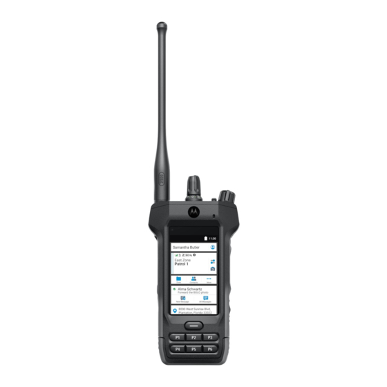
Page 28: Chapter 2: Radio Overview
MN009207A01-AF Chapter 2: Radio Overview Chapter 2 Radio Overview Figure 1: Radio Overview Table 3: Radio Overview Description Number Name Description RF Antenna Transmits and receives electromagnetic waves during transmitting and receiving. Status LED Indicates the operating status of the radio. ABC Switch This switch is usually programmed for zone selection. - Page 29 MN009207A01-AF Chapter 2: Radio Overview Number Name Description P1 to P6 Programmable buttons Use these programmable buttons to access programmed functions or, enable or disable features. Battery Latch This latch locks the battery in place. 2-Dot (Side Bottom) Feature but- Use this programmable button to access a programmed function or, enable or disable a feature.
-
Page 30: Programmable Radio Functions
MN009207A01-AF Chapter 2: Radio Overview Programmable Radio Functions Your system administrator can program the programmable buttons or switches as shortcuts to radio functions depending on the duration of a button press. Contact your system administrator to learn more about the radio functions assigned to the programmable buttons and switches of your radio. - Page 31 MN009207A01-AF Chapter 2: Radio Overview Function Description Mode Select (MS01– MS13) To change to the preset Mode Select zone and channel, press the button. When the Preconfigurable Preset Zone and Channel field is enabled, to save the current zone and channel to one of the Mode Select menus, press and hold the preferred Mode Select menu.
-
Page 32: Viqi
MN009207A01-AF Chapter 2: Radio Overview Function Description Talkaround/Direct (Conventional On- Toggles between using a repeater or communicating directly with another radio. NOTE: If this function is programmed to a radio switch, you cannot change the talkaround/direct mode on the Radio Quick Settings menu. Text Messaging Service (TMS) Allows you to access the Text Messaging Service (TMS) menu. - Page 33 MN009207A01-AF Chapter 2: Radio Overview Feature Examples ● “Zone <zone name>, channel <channel name>” ● “Change zone to <zone name>, channel to <channel name>” ● “Switch zone to <zone name>, channel to <channel name>” Zone To identify your current zone, say: ●...
-
Page 34: Table 6: Viqi Virtual Partner Queries
MN009207A01-AF Chapter 2: Radio Overview Feature Examples Profile To change to a new profile, say: ● “<profile name> profile” ● “Change to <profile name> profile” ● “Switch to <profile name> profile” Scan To start or stop scanning, say: ● “Start scan” ●... -
Page 35: Using Viqi
MN009207A01-AF Chapter 2: Radio Overview Query Examples “Check a <state> license plate” “Look up <state> license plate <alphanumeric string>” Driver's license “Run a <state> driver's license <alphanumeric string>” “Check the state of <state> driver's license <alphanumeric string>” “Look up <state> driver's license<alphanumeric string>” Vehicle Identification “Check Vehicle Identification Number <alphanumeric string>”... - Page 36 MN009207A01-AF Chapter 2: Radio Overview ● To request for more details, say “More details”. ● To complete the Virtual Partner session, say “Complete”.
-
Page 37: Chapter 3: Getting Started
Getting Started This section provides instructions to prepare your radio for use. Attaching and Removing the Battery The radio notifies you if it detects a non-Motorola Solutions battery when powering up, charging, or removed from the charger. Attaching the Battery Procedure: 1. -
Page 38: Inserting Or Removing The Sim Card
MN009207A01-AF Chapter 3: Getting Started Inserting or Removing the SIM Card Prerequisites: Remove the battery from the radio and hold the radio with the speaker grille facing up. Procedure: 1. Gently pull the tab to slide out the SIM card tray. NOTE: The SIM card tray must not be removed with a hook or prying tool. -
Page 39: Charging The Radio
1. Turn off the radio while charging in a single or multiunit charger. 2. Place the radio in a Motorola Solutions-approved charger. NOTE: If the radio must remain powered on in the multiunit charger, LMR PTT is not allowed as possible degradation in performance may occur. -
Page 40: Adjusting The Display Brightness
MN009207A01-AF Chapter 3: Getting Started Adjusting the Display Brightness Procedure: 1. From the Home screen, tap Brightness. 2. Perform one of the following actions: ● Drag the Brightness Slider to set a custom brightness level. ● Tap Auto Brightness to automatically adjust the screen brightness based on the lighting conditions. -
Page 41: Chapter 4: Home Screen Overview
MN009207A01-AF Chapter 4: Home Screen Overview Chapter 4 Home Screen Overview Figure 2: Home Screen Overview Table 7: Home Screen Overview Description Name Description Status Bar Status icons appear in the status bar to pro- vide device status and feature notifications. Identity and Status Widget Displays your email account when you are logged in. -
Page 42: On-Screen Keyboard Overview
MN009207A01-AF Chapter 4: Home Screen Overview Name Description Menu Feature Launcher Widget Displays the top two priority features provi- sioned in the Customer Programming Soft- ware (CPS). More option contains all other pro- grammed menu items. Messages Widget Allows you to compose a new text message and view all messages in the inbox. -
Page 43: Identity And Status Widget
MN009207A01-AF Chapter 4: Home Screen Overview Figure 3: On-Screen Keyboard Overview Description Tap to type in uppercase. Double-tap for caps lock. Tap to input numbers, punctuation, or symbols. Tap to insert space. Double-tap to insert a period. Enter Backspace Identity and Status Widget The Identity and Status Widget displays the identity of the radio with either the Radio Alias, Soft ID, or User Login. -
Page 44: User Login Feature
MN009207A01-AF Chapter 4: Home Screen Overview 4.2.2 User Login Feature This feature allows you to take on a friendly username such as Text Messaging Service (TMS). You can still send text messages without logging in as a user. The user login feature only enables the recipient of your message to identify you as the sender by assigning a username to your message. -
Page 45: Multi Factor Authentication Pin
MN009207A01-AF Chapter 4: Home Screen Overview Procedure: 1. From the Home screen, tap Shift Manager Launcher. 2. Tap Soft ID, then enter your Soft ID. 3. Tap Done to confirm. NOTE: If you leave the Soft ID empty, the Work Manager Widget displays the Radio Alias ID if it is enabled. -
Page 46: Resetting Your Mfa Pin
MN009207A01-AF Chapter 4: Home Screen Overview 6. To verify the new PIN number, reenter the PIN number and tap Result: When your new MFA PIN is successfully registered, the radio displays a positive notification. 4.2.4.3 Resetting Your MFA PIN If you forget your Multi Factor Authentication (MFA) PIN, you can reset this PIN. Procedure: 1. -
Page 47: Logging In To Commandcentral
MN009207A01-AF Chapter 4: Home Screen Overview After you have logged in, you can view your agency details (Agency name, Unit ID, Auto logout date and time). You will be notified when you are about to be logged out when you see a logout timer on the widget. The timer is displayed 1 hour before the logout time if the session timeout is set to less than 29 days, or 20 hours before if session timeout is set to more than 29 days. -
Page 48: Updating Unit Id
MN009207A01-AF Chapter 4: Home Screen Overview 4.2.6 Updating Unit ID Prerequisites: Field users must log in before changing Unit ID. Procedure: 1. From the Home screen, tap Shift Manager Launcher. 2. Update the Unit ID by using the following options: Option Actions Updating Unit ID for the first time... -
Page 49: Application Session Lock
MN009207A01-AF Chapter 4: Home Screen Overview 4.2.8 Application Session Lock This feature adds App Services Session Lock. When the device becomes idle and reaches a timeout, the device requires the field user to type a PIN to unlock SmartMapping, SmartIncident, SmartMessaging and ViQi VP Common Queries, which can carry sensitive data. -
Page 50: Unlocking Session Lock
MN009207A01-AF Chapter 4: Home Screen Overview Procedure: 1. You can reset the PIN by using the following options: Option Actions Resetting from PIN Settings a. From the Home screen, tap Shift Manager Launcher. b. Tap PIN Settings → Forgot PIN → RE- SET. -
Page 51: Radio Icons
MN009207A01-AF Chapter 4: Home Screen Overview 4.3.1 Radio Icons These icons appear at the status bar to provide device-specific information or status. Icon Name Description Battery Indicates the remaining battery level of the radio. The icon blinks when the battery level drops to (Front display) 10% or lower. - Page 52 MN009207A01-AF Chapter 4: Home Screen Overview These icons appear at the Radio Control Widget to provide information or status of LMR-specific features. Icon Name Description Received Signal The number of bars represents the received signal Strength Indicator strength of the current site in trunking mode. (RSSI) Receiving The radio is receiving a call or data.
-
Page 53: Led Indications
MN009207A01-AF Chapter 4: Home Screen Overview Icon Name Description Enhanced Zone Bank – Icons "A" to "Y" indicates that the radio is in the dedicated zone bank. User Login Indicator (IP Steady – The user is associated with the radio. Packet Data) Blinking –... - Page 54 MN009207A01-AF Chapter 4: Home Screen Overview Color Call State Yellow Receiving and Unmuted Voice Transmission Gray Unprogrammed...
-
Page 55: Chapter 5: General Radio Operation
MN009207A01-AF Chapter 5: General Radio Operation Chapter 5 General Radio Operation This chapter explains the general operations of your radio. Responding to Notifications The Notification Center provides concise information about an activity or event. Procedure: 1. Drag down the Status Bar to open the Notification Center. 2. -
Page 56: Toggling The Controls And Buttons Tones On And Off
MN009207A01-AF Chapter 5: General Radio Operation Toggling the Controls and Buttons Tones On and Procedure: 1. From the Home screen, tap More. 2. To toggle the controls and buttons tones on and off, tap Tones. Control Lock This feature allows you to lock and unlock the radio switches, buttons, knobs, and touch screen display. 5.4.1 Locking the Controls Procedure:... -
Page 57: Selecting A Radio Profile
MN009207A01-AF Chapter 5: General Radio Operation Selecting a Radio Profile This feature allows you to manually switch the visual and audio settings of the radio. The display, backlight, alert tones, and audio settings are defined according to the programmed radio settings of each radio profile. Procedure: 1. -
Page 58: Accessing The General Radio Information
MN009207A01-AF Chapter 5: General Radio Operation 5.7.1 Accessing the General Radio Information Procedure: To access the general radio information, perform one of the following: Option Actions Accessing the Radio Information a. From the Home screen, tap More. b. Tap Info → Radio Information. ●... -
Page 59: Chapter 6: Zone And Channel Selection
MN009207A01-AF Chapter 6: Zone and Channel Selection Chapter 6 Zone and Channel Selection This chapter explains the operations to select a zone or channel on your radio. A zone is a group of channels. Selecting Zones Procedure: Use one of the following methods to select a zone. Option Actions Slide the ABC switch to the required position. -
Page 60: Selecting Channels
MN009207A01-AF Chapter 6: Zone and Channel Selection ● For the Basic Zone Bank feature, the radio displays the icon of the selected zone. ● For the Enhanced Zone Bank feature, the radio displays the icon of the selected zone bank. 2. -
Page 61: Chapter 7: Dynamic Zone Programming
MN009207A01-AF Chapter 7: Dynamic Zone Programming Chapter 7 Dynamic Zone Programming Dynamic Zone Programming (DZP) provides one or more Dynamic Zones to store frequently used channels for conventional or trunking. With Dynamic Zone, you can select channels from different zones without first switching to that particular zone to select a channel. - Page 62 MN009207A01-AF Chapter 7: Dynamic Zone Programming 4. At the Program Zone screen, manage channels in the Dynamic Zone by using the following options. Option Actions Adding channels to the Dynamic Zone a. Tap the Add icon of a Blank chan- nel.
-
Page 63: Chapter 8: Zone-To-Zone Cloning
MN009207A01-AF Chapter 8: Zone-to-Zone Cloning Chapter 8 Zone-to-Zone Cloning Zone Cloning clones conventional zones from one radio to another. You can select the followings zones from a source radio and clone them into a target radio. ● Clone enabled zones ●... -
Page 64: Chapter 9: Multiple Private Line
MN009207A01-AF Chapter 9: Multiple Private Line Chapter 9 Multiple Private Line Multiple Private Line (MPL) is a feature that allows user to modify the PL/DPL codes of the current mode by selecting from a predefined list of codes. For the purpose of accessing different communication sub-groups, repeaters and others, user no longer need to program multiple channels of the same frequency with different PL/DPL codes. -
Page 65: Chapter 10: Types Of Radio Calls
MN009207A01-AF Chapter 10: Types of Radio Calls Chapter 10 Types of Radio Calls Your radio can make talkgroup, private, and enhanced private calls in conventional and/or trunking mode. Call Type Conventional Trunking Mode SmartConnect Mode Talkgroup Call A Talkgroup Call is a point-to-multipoint call operation. -
Page 66: Making Calls On The Radio
MN009207A01-AF Chapter 10: Types of Radio Calls 10.1 Making Calls on the Radio Procedure: Perform one of the following actions based on the type of radio call: Option Actions Talkgroup Call a. Ensure that you are in the preferred zone and channel. -
Page 67: Receiving Calls On The Radio
MN009207A01-AF Chapter 10: Types of Radio Calls Option Actions Dual Tone Multi-Frequency (DTMF) Transmission Perform one of the following actions: If Hot Keypad mode enabled: a. From the Menu Feature Launcher, tap Dialer → More → DTMF. b. Press the PTT button while entering the DTMF number. - Page 68 MN009207A01-AF Chapter 10: Types of Radio Calls Procedure: 1. Press the preprogrammed Priority Dispatch button. NOTE: Harris' Symphony Dispatch Console supports this feature. ™ A tone sounds and the radio enters Priority Dispatch mode. The radio exits this mode when the Priority Dispatch Time Out Timer expires.
-
Page 69: Chapter 11: Emergency Operation
MN009207A01-AF Chapter 11: Emergency Operation Chapter 11 Emergency Operation The Emergency feature is used to indicate a critical situation. An emergency signal overrides any other communication over the selected channel. Your radio supports the following Emergency modes: ● Emergency Alarm ●... -
Page 70: Sending Emergency Alarms
MN009207A01-AF Chapter 11: Emergency Operation 11.2 Sending Emergency Alarms This feature allows you to send a data transmission, which identifies the radio sending the emergency, to the dispatcher. Procedure: Press the programmed Top (Orange) button for emergency. Your radio shows the following indications: ●... -
Page 71: Exiting Emergency Operation
MN009207A01-AF Chapter 11: Emergency Operation Option Actions Emergency Call with Hot Mic Speak into the microphone. NOTE: The Hot Mic applies to the first voice transmission from your radio during the Emergency call. For subsequent transmissions in the same Emergency call, you must press the PTT button. -
Page 72: Remote Emergency
MN009207A01-AF Chapter 11: Emergency Operation 11.5 Remote Emergency The Remote Emergency feature allows you to remotely launch the emergency feature on a target radio. You can send the Remote Emergency request to radios from recently transmitted or received calls that are stored. -
Page 73: Sending Remote Emergency From Menu Feature Launcher
MN009207A01-AF Chapter 11: Emergency Operation 5. To send Remote Emergency, press the PTT button. Result: If the ID of the target radio is valid, your radio displays Sending remote emergency... and saves the ID as the last Remote Emergency ID. If the ID of the target radio is invalid, your radio displays an invalid ID notification. -
Page 74: Emergency Keep-Alive
MN009207A01-AF Chapter 11: Emergency Operation Procedure: 1. To view notification, drag down the Status Bar to open the Notification Center. 2. To exit Emergency mode, tap CANCEL → YES. Canceling Emergency mode dismisses Emergency notification, and your radio returns to normal operation. -
Page 75: Viewing Received Emergency Beacon
MN009207A01-AF Chapter 11: Emergency Operation ● Tap Dismiss to dismiss the beacon. NOTE: If there are multiple beacons, the radio displays the recent beacon received. 11.7.3 Viewing Received Emergency Beacon Procedure: From the Home screen, tap Beacon. NOTE: The received beacons will be removed from the list after four minutes. -
Page 76: Chapter 12: Fireground
MN009207A01-AF Chapter 12: Fireground Chapter 12 Fireground The portable Fireground Communications System is designed for deployment at an incident scene. It consists of central components that provide on-scene and in building radio coverage, and enhanced personnel accountability and monitoring: ● Your APX portable radios ●... -
Page 77: Responding To Evacuation Indicator
MN009207A01-AF Chapter 12: Fireground 3. Perform one of the following actions: ● Press and hold the preprogrammed Volume Set button to hear the volume set tone. Adjust the Volume Control Knob if necessary. Release the Volume Set button. ● At the desired Fireground zone and channel, press the preprogrammed Monitor button and listen for activity. -
Page 78: Chapter 13: Tactical Public Safety (Conventional Only)
MN009207A01-AF Chapter 13: Tactical Public Safety (Conventional Only) Chapter 13 Tactical Public Safety (Conventional Only) Tactical Public Safety (TPS) enables the member of a group to identify the start and the end of a transmission by displaying the caller name or ID on the radio display. 13.1 Using TPS Normal Transmission Procedure:... -
Page 79: Chapter 14: Fall Alert
MN009207A01-AF Chapter 14: Fall Alert Chapter 14 Fall Alert Fall Alert is a supporting feature of the Emergency operation. The Emergency feature must be programmed for Fall Alert to operate. Your radio activates the Fall Alert feature when it achieves or exceeds a tilt angle threshold or a combination of the angle threshold and radio motion below the motion sensitivity level. -
Page 80: Exiting Fall Alert
MN009207A01-AF Chapter 14: Fall Alert Postrequisites: If Fall Alert is configured but the condition does not trigger the activation of the feature, send the radio to a qualified technician. 14.3 Exiting Fall Alert Procedure: To exit Fall Alert mode, tap Cancel. 14.4 Reinitiating Fall Alert Procedure:... -
Page 81: Chapter 15: Secure Operations
MN009207A01-AF Chapter 15: Secure Operations Chapter 15 Secure Operations Secure radio operation provides the highest commercially available level of voice security on both trunked and conventional channels. By default, the radio automatically enters the encrypted environment without having to manually select or clear the secure transmission. -
Page 82: Selecting Encryption Keys (Conventional Only)
MN009207A01-AF Chapter 15: Secure Operations 15.4 Selecting Encryption Keys (Conventional Only) This feature allows you to change the encryption key from an active keyset. Procedure: 1. From the Home screen, tap More. 2. Tap Select Key, then select the required encryption key. 15.5 Changing Encryption Keysets Procedure:... -
Page 83: Chapter 16: Scan
MN009207A01-AF Chapter 16: Scan Chapter 16 Scan This feature allows you to monitor traffic on different channels by scanning a programmed list of channels. Scanning is halted if you initiate a call and resumes when the call has ended. 16.1 Toggling the Scan Feature On and Off Procedure: Perform one of the following actions:... -
Page 84: Restoring A Nuisance Channel
MN009207A01-AF Chapter 16: Scan 16.4 Restoring a Nuisance Channel Procedure: To restore the deleted nuisance channel, perform one of the following actions: ● Press the programmed Scan button to turn off scan and press this button again to turn on scan. ●... -
Page 85: Chapter 17: Scan Lists
MN009207A01-AF Chapter 17: Scan Lists Chapter 17 Scan Lists Scan lists are created and assigned to individual channels or groups. Your radio scans for voice activity by cycling through the channel or group. The sequence of scan is as specified in the scan list for the current channel or group. -
Page 86: Chapter 18: Smartprogramming
MN009207A01-AF Chapter 18: SmartProgramming Chapter 18 SmartProgramming The SmartProgramming service enables radio programming and updates over LTE broadband connection while the radios are in use. Seamless updates of firmware (full and differential), radio configuration and security updates are scheduled by the radio system administrator and the radio user is given a choice to install immediately or delay for later. -
Page 87: Firmware Update Notification Actions
MN009207A01-AF Chapter 18: SmartProgramming Programming your radio using CPS is the same procedure as programming any APX radios. You can refer to the APX CPS Radio Management User Guide, MN003621A01 for information on programming APX radios. ™ NOTE: Your radio firmware must be the 2021.4 or later and CPS must be R26.00.00 or later. 18.2 Firmware Update Notification Actions Figure 4: Firmware Update Notification... -
Page 88: Chapter 19: Over-The-Air Programming (Pop 25)
MN009207A01-AF Chapter 19: Over-The-Air Programming (POP 25) Chapter 19 Over-The-Air Programming (POP 25) Over-The-Air_Programming (OTAP) allows codeplug programming over an ASTRO P25 data channel or POP 25. The codeplug of the radio can be accessed or upgraded through a wireless radio network. Full use of the radio is retained during the data transfer without interrupting communication. -
Page 89: Chapter 20: Connectivity
SmartConnect and SmartLocate features. In some countries, an LTE SIM may be installed into the radio by Motorola Solutions before delivery. Each preinstalled SIM is locked to the specific radio so it cannot operate in any other radio or device. The SIM is located in a slot in the rear chassis. -
Page 90: Wi-Fi
MN009207A01-AF Chapter 20: Connectivity Your radio displays the SmartConnect capable icon on the SmartConnect enabled channel. When the device is connected to an available network, the radio displays SmartConnect connection icon Your radio displays Out of Range when both LMR and SmartConnect are unavailable. 20.3 Wi-Fi You can connect your radio to a Wi-Fi network for wireless programming and SmartConnect features. -
Page 91: Toggling Bluetooth Audio On And Off
4. Tap Forget twice, to confirm the request. 20.5 P25 Digital Vehicular Repeater System Motorola Solutions offers an MSI Certified APX compatible, third party, P25 Digital Vehicular Repeater System (DVRS). This provides low-cost portable radio coverage in areas where only mobile radio coverage is available. -
Page 92: Sideloading Files On The Radio Using Usb Cable
MN009207A01-AF Chapter 20: Connectivity 20.6 Sideloading Files on the Radio Using USB Cable Procedure: 1. Connect your radio to your PC using a USB cable. 2. From the radio home screen, select Settings → Advance → USB Connection → File Transfer. 3. -
Page 93: Chapter 21: Location
MN009207A01-AF Chapter 21: Location Chapter 21 Location The Global Navigation Satellite System (GNSS) integrates information from the Global Positioning System (GPS) and the Global Navigation Satellite System (GLONASS) to determine the approximate geographical location of your radio. The radio also supports the following features: Indoor Positioning This feature allows your radio location to be tracked through Wi-Fi or cellular modem when satellite signal is unavailable. -
Page 94: Waypoints
MN009207A01-AF Chapter 21: Location 2. Perform one of the following actions: Option Actions If SmartMapping is enabled Perform one of the following actions: ● In Map view, tap My Location and tap the address. ● In List view, tap the address in My Loca- tion. -
Page 95: Smartmapping
MN009207A01-AF Chapter 21: Location Option Actions Changing the location settings a. Tap Location settings. b. Perform one of the following actions: ● To change or disable the friendly loca- tion format, tap Friendly format. ● To change the coordinate format, tap Coordinate format. -
Page 96: Viewing Units/Devices
MN009207A01-AF Chapter 21: Location Icon Name Description Unit label Tap a unit on the map to show dialog box and location accura- Location accuracy indicator Indicates the confidence range for the actual location of the unit on the map. 21.4.1 Viewing Units/Devices Procedure: 1. -
Page 97: Creating Waypoints In Map View
MN009207A01-AF Chapter 21: Location 21.4.2 Creating Waypoints in Map View Prerequisites: To create a Waypoint, enable Waypoints from the filter by tapping More. NOTE: Ensure that you save all the changes. Procedure: 1. From the Home screen, tap the Location Widget. 2. -
Page 98: Managing Options In List View
MN009207A01-AF Chapter 21: Location Option Actions Changing base map Tap Map layers → <required map view>. Viewing Waypoints Tap Waypoints. Opening location settings Tap Settings. Viewing SmartMapping application notes Tap About map. Activating or deactivating clustering Tap App Settings → Clustering → Restart. 21.4.5 Managing Options in List View Procedure:... -
Page 99: Chapter 22: Mission Critical Geofence (Astro 25 Trunking)
MN009207A01-AF Chapter 22: Mission Critical Geofence (ASTRO 25 Trunking) Chapter 22 Mission Critical Geofence (ASTRO 25 Trunking) This feature allows the radio to use the Global Positioning System (GPS) receiver to determine its location at frequent intervals and evaluate if the radio is within the Geofence area in real time. Geofence is a virtual perimeter based on the GPS to define a geographical area on earth. -
Page 100: Entry To Mission Critical Geofence
MN009207A01-AF Chapter 22: Mission Critical Geofence (ASTRO 25 Trunking) When the radio exits the Geofence area, your radio reverts to original channel or newly assigned talkgroup. The radio display shows the new channel together with Voice Announcement to indicate the changes. Voice Announcement of the new channel only works if that channel is configured with Voice Announcement. -
Page 101: Chapter 23: Contacts
MN009207A01-AF Chapter 23: Contacts Chapter 23 Contacts This feature provides address-book capabilities on your radio. Each entry corresponds to an alias (name) and ID (number) that you use to initiate a call. Contact entries are alphabetically sorted according to the entry alias. -
Page 102: Figure 6: Call List Tab
MN009207A01-AF Chapter 23: Contacts Table 12: Contacts Tab Label Name Description Saved Contacts Your radio displays the numbers and names of saved contacts. Favorites Contacts Your radio displays the frequently contacted numbers or names. Floating Action Button (FAB) Allows you to access contact options. Quick Action Allows you to perform the assigned radio func- tion. -
Page 103: Accessing Contacts
MN009207A01-AF Chapter 23: Contacts Table 13: Call List Tab Label Name Description Last Used Number Your radio displays the last number received or dialed. Radio ID Call List Your radio displays the numbers and names of saved Radio ID. My Information Your radio displays your user and group number associated with the current channel. -
Page 104: Chapter 24: Recent Calls
MN009207A01-AF Chapter 24: Recent Calls Chapter 24 Recent Calls Recent call menu allows you to view the recent incoming and outgoing call information. You can view the information of the following type of calls: ● Emergency Calls ● Individual Calls ●... -
Page 105: Accessing Instant Recall
MN009207A01-AF Chapter 24: Recent Calls Option Actions Deleting selected calls a. Tap on the More button. b. Select Select to Delete. c. Select the calls to delete. d. Tap DELETE. Result: When you have successfully deleted all calls, your display shows All entries deleted and the Recent Calls list is empty. -
Page 106: Chapter 25: Smartmessaging
MN009207A01-AF Chapter 25: SmartMessaging Chapter 25 SmartMessaging SmartMessaging allows you to send or receive messages over a broadband connection. Messages are in the form of predefined Quick Text Messages. The messages are synced to a server. The messages are available when you sign in from any devices or shared devices. -
Page 107: Viewing Messages
MN009207A01-AF Chapter 25: SmartMessaging 2. Select the recipient by using one of the following options. Option Actions Sending messages to an individual a. From ALL, tap the required recipient from the list. b. Tap Quick Message or Choose Text. c. Send the message by tapping the required quick message. -
Page 108: Accessing Multimedia Attachments
MN009207A01-AF Chapter 25: SmartMessaging 2. Delete messages by using the following options. Option Actions Deleting a Message a. Tap and hold the required message. b. Tap Delete. Deleting More than One Message a. Tap More → Select to Delete. b. To select, tap the required messages. c. - Page 109 MN009207A01-AF Chapter 25: SmartMessaging Option Actions Viewing a sent location a. Tap the required message with a sent loca- tion. The display shows the location, and the ad- dress is updated to the friendly address. Forwarding a multimedia attachment a. Open an attachment from the selected message.
-
Page 110: Chapter 26: Messages
MN009207A01-AF Chapter 26: Messages Chapter 26 Messages This feature allows you to quickly send and receive messages directly from your radios. The maximum length of a text message is 200 characters. Local date and time is timestamped on the messages. NOTE: This feature must be preprogrammed by a qualified radio technician. - Page 111 MN009207A01-AF Chapter 26: Messages Option Actions Deleting selected messages a. Tap More → Select to Delete → <required message>. b. Tap Delete. Deleting a conversation a. Tap More → Delete → <required conversation>. b. Tap Delete.
-
Page 112: Chapter 27: Voice Announcement
MN009207A01-AF Chapter 27: Voice Announcement Chapter 27 Voice Announcement This feature enables the radio to audibly indicate the current feature mode, zone, or channel assigned to the user. The available voice announcement (VA) priority options are: High Voice announcement is enabled even when the radio is receiving calls. Voice announcement is disabled when the radio is receiving calls. -
Page 113: Chapter 28: Radio Inhibit
MN009207A01-AF Chapter 28: Radio Inhibit Chapter 28 Radio Inhibit This feature allows the system administrator to put a radio into a nonfunctional state when the radio is missing or in an unknown hand. The radio stays in this state regardless of its power changes. NOTE: If the radio has Intersystem roaming capability, the system administrator is able to put the radio into a nonfunctional state when the missing radio roams to another system. -
Page 114: Chapter 29: Smart Ptt (Conventional Only)
MN009207A01-AF Chapter 29: Smart PTT (Conventional Only) Chapter 29 Smart PTT (Conventional Only) Smart PTT is a per-personality, programmable feature used to keep radio users from talking over other radio conversations. When Smart PTT is enabled in your radio, you cannot transmit on an active channel. The following table shows the variations of Smart PTT. -
Page 115: Chapter 30: Remote Monitor
MN009207A01-AF Chapter 30: Remote Monitor Chapter 30 Remote Monitor This feature allows the system administrator to turn on the microphone of a targeted radio with a subscriber alias or ID. When remote monitor feature is activated, the audio transmission can be configured in Customer Programming Software (CPS) to route the audio to the radio internal microphone, wired Remote Speaker Microphone (RSM), or Bluetooth wireless microphone. -
Page 116: Chapter 31: Toggling Between Repeater And Direct Operation
MN009207A01-AF Chapter 31: Toggling between Repeater and Direct Operation Chapter 31 Toggling between Repeater and Direct Operation Repeater operation increases radio coverage area by connecting with other radios through a repeater. Direct or "talkaround" operation bypasses the repeater and connects directly to another radio. You can select either one of these operations on your radio. -
Page 117: Chapter 32: Trunking System Controls
MN009207A01-AF Chapter 32: Trunking System Controls Chapter 32 Trunking System Controls This chapter explains the trunking system control features in your radio. 32.1 Operating in Failsoft System The failsoft system ensures continuous radio communication during a trunked system failure. When the radio goes into failsoft operation, it automatically switches to a failsoft channel which allows your radio to transmit and receive in conventional operation on a predetermined frequency. -
Page 118: Site Search
MN009207A01-AF Chapter 32: Trunking System Controls 32.5 Site Search When searching for a site, your radio is inoperable. In the site search mode, your radio scans for trunked control channels but has yet to connect to the trunking system or reach other trunking states. Other trunking states are such as Out of Range and Imbalanced Coverage. -
Page 119: Chapter 33: Dynamic Regrouping (Trunking Only)
MN009207A01-AF Chapter 33: Dynamic Regrouping (Trunking Only) Chapter 33 Dynamic Regrouping (Trunking Only) This feature allows the dispatcher to temporarily reassign selected radios to a particular channel to communicate with each other. When your radio is dynamically regrouped, it receives a dynamic regrouping command and automatically switches to the dynamically regrouped channel. -
Page 120: Chapter 34: Front Panel Programming
MN009207A01-AF Chapter 34: Front Panel Programming Chapter 34 Front Panel Programming You are able to customize certain feature parameters in Front Panel Programming (FPP) to enhance the use of your radio. The radio can be programmed in two ways: ● Front Panel Programming (FPP) using the front panel controls of the radio. - Page 121 MN009207A01-AF Chapter 34: Front Panel Programming 2. Enter the current PIN 3. Enter the new PIN. 4. To accept the entry, enter the new PIN again. 34.3 Editing FPP Mode Parameters Perform the following actions as required while navigating through the mode parameters. Procedure: 1.
- Page 122 MN009207A01-AF Chapter 35: Accessories Chapter 35 Accessories Not all accessories are FCC certified to operate with all radio models, band splits, or both. See the radio price pages for a list of FCC certified accessories or contact your sales representative for accessory compatibility. https://www.motorolasolutions.com to know more about the accessories supported by this radio.
Need help?
Do you have a question about the APX N70 and is the answer not in the manual?
Questions and answers