Table of Contents
Advertisement
Available languages
Available languages
Quick Links
Advertisement
Chapters
Table of Contents

Related Manuals for Lenze DeviceNet E94AYCDN


Summary of Contents for Lenze DeviceNet E94AYCDN
- Page 1 EDK94AYCDN L−force Communication .S!b Montageanleitung Mounting Instructions Instructions de montage Instrucciones para el montaje Istruzioni per il montaggio DeviceNet E94AYCDN Kommunikationsmodul Communication module Module de communication Módulo de comunicaciones Modulo di comunicazione...
- Page 2 Lesen Sie zuerst diese Anleitung, bevor Sie mit den Arbeiten beginnen! Beachten Sie die enthaltenen Sicherheitshinweise. Please read these instructions before you start working! Follow the enclosed safety instructions. Veuillez lire attentivement cette documentation avant toute action ! Les consignes de sécurité doivent impérativement être respectées. Lea las instrucciones antes de empezar a trabajar.
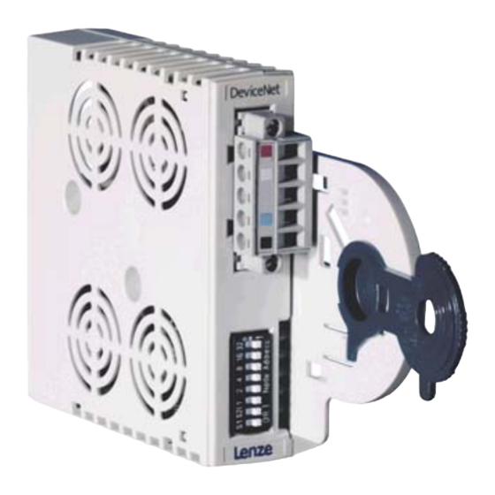
- Page 3 E894YCDN001B 0Abb. 0Tab. 0 Pos. Beschreibung Ausführliche Information ^ 20 S225 DIP−Schalter zur Einstellung der Stationsadresse (MAC ID) Übertragungsrate ^ 16 X225 Anschluss für externe Spannungsversorgung und DeviceNet−Anschluss 5−polige Steckerleiste mit Schraubanschluss ^ 22 LED−Statusanzeigen zur Diagnose EDK94AYCDN DE/EN/FR/ES/IT 4.0...
-
Page 4: Table Of Contents
Inhalt Über diese Dokumentation ......... . Verwendete Konventionen . -
Page 5: Über Diese Dokumentation
Kommunikationsmodul E94AYCDN 01.00 DeviceNet Zielgruppe Diese Dokumentation wendet sich an Personen, die das beschriebene Produkt nach Projekt- vorgabe installieren und in Betrieb nehmen. Tipp! Informationen und Hilfsmittel rund um die Lenze−Produkte finden Sie im Download−Bereich unter www.lenze.com EDK94AYCDN DE/EN/FR/ES/IT 4.0... -
Page 6: Verwendete Konventionen
Über diese Dokumentation Verwendete Konventionen Verwendete Konventionen Diese Dokumentation verwendet folgende Konventionen zur Unterscheidung verschiede- ner Arten von Information: Informationsart Auszeichnung Beispiele/Hinweise Zahlenschreibweise Dezimaltrennzeichen Punkt Es wird generell der Dezimalpunkt verwendet. Beispiel: 1234.56 Symbole Seitenverweis Verweis auf eine andere Seite mit zu- sätzlichen Informationen Beispiel: 16 = siehe Seite 16... -
Page 7: Verwendete Hinweise
Über diese Dokumentation Verwendete Hinweise Verwendete Hinweise Um auf Gefahren und wichtige Informationen hinzuweisen, werden in dieser Dokumenta- tion folgende Piktogramme und Signalwörter verwendet: Sicherheitshinweise Aufbau der Sicherheitshinweise: Gefahr! (kennzeichnet die Art und die Schwere der Gefahr) Hinweistext (beschreibt die Gefahr und gibt Hinweise, wie sie vermieden werden kann) Piktogramm und Signalwort Bedeutung Gefahr von Personenschäden durch gefährliche elektri-... - Page 8 Über diese Dokumentation Verwendete Hinweise Anwendungshinweise Piktogramm und Signalwort Bedeutung Wichtiger Hinweis für die störungsfreie Funktion Hinweis! Nützlicher Tipp für die einfache Handhabung Tipp! Verweis auf andere Dokumentation EDK94AYCDN DE/EN/FR/ES/IT 4.0...
-
Page 9: Sicherheitshinweise
Sicherheitshinweise Sicherheitshinweise Gefahr! Unsachgemäßer Umgang mit dem Kommunikationsmodul und dem Grundgerät kann schwere Personenschäden und Sachschäden verursachen. Beachten Sie die in der Dokumentation zum Grundgerät enthaltenen Sicherheitshinweise und Restgefahren. Stop! Elektrostatische Entladung Durch elektrostatische Entladung können elektronische Bauteile innerhalb des Kommunikationsmoduls beschädigt oder zerstört werden. -
Page 10: Produktbeschreibung
Produktbeschreibung Funktion Produktbeschreibung Funktion Das Kommunikationsmodul koppelt Lenze Servo Drives 9400 an das Kommunikationssys- tem DeviceNet. Bestimmungsgemäße Verwendung Das Kommunikationsmodul ... ƒ ist eine Zubehör−Baugruppe, die mit folgenden Lenze Grundgeräten eingesetzt werden kann: Produktreihe Typenbezeichnung ab Hardwarestand ab Softwarestand Servo Drives 9400 E94AxxExxxx 01.50... -
Page 11: Identifikation
Produktbeschreibung Identifikation Identifikation E94YCDN005 ‚ ƒ 1.00 Produktreihe Gerätegeneration Modulkennung: Erweiterungsmodul Modultyp: Kommunikationsmodul DeviceNet Hardwarestand Softwarestand EDK94AYCDN DE/EN/FR/ES/IT 4.0... -
Page 12: Technische Daten
Technische Daten Allgemeine Daten Technische Daten Allgemeine Daten Bereich Werte Bestell−Bezeichnung E94AYCDN Kommunikationsprofil DeviceNet Schnittstelle 5−polige Steckerleiste mit Schraubanschluss Kommunikationsmedium EN 11898 Netzwerktopologie Beidseitig abgeschlossene Linie (R = 120 DeviceNet−Teilnehmeranzahl max. 64 Max. Leitungslänge 500 m (abhängig von der gewählten Übertragungsrate und dem verwendeten Kabeltyp) DeviceNet−Teilnehmer Slave... -
Page 13: Abmessungen
Technische Daten Abmessungen Abmessungen E94YCXX005 89 mm 134 mm 87 mm 23 mm EDK94AYCDN DE/EN/FR/ES/IT 4.0... -
Page 14: Mechanische Installation
Mechanische Installation Mechanische Installation Montage E94YCXX001G Demontage E94AYCXX001H EDK94AYCDN DE/EN/FR/ES/IT 4.0... -
Page 15: Elektrische Installation
Elektrische Installation DeviceNet−Anschluss Elektrische Installation DeviceNet−Anschluss Für die Kommunikation mit dem Scanner und allen weiteren Komponenten müssen die Servo Drives 9400 mit Kommunikationsmodulen bestückt werden. Eine DeviceNet−Linie kann aus maximal 64 Teilnehmern bestehen. Zu den Teilnehmern zäh- len ... ƒ die angeschlossenen Grundgeräte; ƒ... - Page 16 Elektrische Installation DeviceNet−Anschluss Belegung der Steckerleiste Der Busanschluss des Kommunikationsmoduls erfolgt über die 5−polige Steckerleiste mit Doppel−Schraubanschluss (X225). E94YCDN001C Bezeichnung Kabelfarbe Beschreibung Externe Spannungsversorgung U = 24 V DC = 170 mA CAN_H weiß Datenleitung / Eingang für Busabschlusswiderstand (120 SHIELD Schirmung CAN_L...
- Page 17 Elektrische Installation DeviceNet−Anschluss Spezifikation des Busabels Die Teilnehmer am Bussystem müssen mit einer der DeviceNet−Spezifikation (DeviceNet Adaption of CIP, Edition 1.1, Volume 3) entsprechenden Feldbusleitung ˘ einem DeviceNet Thick− oder Thin−Kabel ˘ miteinander verdrahtet werden. Hersteller von DeviceNet Thick− und Thin−Kabel sind z. B. Belden Inc., Lapp, C&M Corp. und Madison Cable Corp. Hinweis! Wenn Sie die Verwendung eines Thick−...
- Page 18 Elektrische Installation DeviceNet−Anschluss Busleitungslänge In Abhängigkeit der Übertragungsrate und des verwendeten Kabelstyps (Thick−Kabel / Thin−Kabel) sind folgende Busleitungslängen möglich: Übertragungsrate [kBit/s] Busleitungslänge [m] Thick−Kabel Thin−Kabel Bei gemischter Verwendung der Kabeltypen "Thick" und "Thin" können Sie die maximalen Kabellängen in Abhängigkeit der Übertragungsraten wie folgt bestimmen: Übertragungsrate [kBit/s] Max.
-
Page 19: Spannungsversorgung
Elektrische Installation Spannungsversorgung Spannungsversorgung Externe Versorgung Das Kommunikationsmodul wird extern über die DeviceNet−Leitung an der 5−poligen Steckerleiste (X225) mit Spannung versorgt. Hinweis! Verwenden Sie ein nach EN 61800−5−1 sicher getrenntes Netzteil ("SELV"/"PELV"). ƒ Die externe Spannungsversorgung des Kommunikationsmoduls ist immer notwendig. -
Page 20: Inbetriebnahme
Schalter 32, 8, 4 = ON (32 + 8 + 4 = 44) Gültiger Adressbereich: 0 … 63 keine Funktion Die Lenze−Einstellung aller Schalter ist OFF. Hinweis! Beachten Sie die Informationen zur Einstellung der DIP−Schalter im Kommunikationshandbuch E94AYCDN (DeviceNet), Kapitel "Inbetriebnahme"... -
Page 21: Vor Dem Ersten Einschalten
Inbetriebnahme Vor dem ersten Einschalten Vor dem ersten Einschalten Stop! Bevor Sie das Grundgerät mit dem Kommunikationsmodul erstmalig einschalten, überprüfen Sie die gesamte Verdrahtung auf Vollständigkeit, Kurzschluss und Erdschluss. ƒ ob das Bussystem beim physikalisch ersten und letzten Busteilnehmer ƒ durch den Busabschlusswiderstand abgeschlossen ist. -
Page 22: Diagnose
Diagnose LED−Statusanzeigen Diagnose LED−Statusanzeigen Pos. Farbe / Zustand Beschreibung grün an Das Kommunikationsmodul ist mit Spannung versorgt und hat eine Verbindung zum Grundgerät. grün blinkt Das Kommunikationsmodul ist mit Spannung versorgt, hat aber keine Verbindung zum Grundgerät (Grundgerät ist ausgeschaltet, in der Initialisierungsphase oder nicht vorhanden). - Page 23 E894YCDN001B 0Fig. 0Tab. 0 Pos. Description Detailed information ^ 40 S225 DIP switch to set the Station address (MAC ID) Baud rate ^ 36 X225 Port for the external voltage supply and for connecting DeviceNet 5−pole plug connector with screw connection ^ 42 LED status displays for diagnostics EDK94AYCDN DE/EN/FR/ES/IT 4.0...
- Page 24 Contents About this documentation ......... . . Conventions used .
-
Page 25: About This Documentation
Target group This documentation is intended for persons who install and commission the described product according to the project requirements. Tip! Information and tools concerning the Lenze products can be found in the download area at www.lenze.com EDK94AYCDN DE/EN/FR/ES/IT 4.0... -
Page 26: Conventions Used
About this documentation Conventions used Conventions used This documentation uses the following conventions to distinguish between different types of information: Type of information Identification Examples/notes Numbers Decimal separator Point The decimal point is used throughout this documentation. Example: 1234.56 Symbols Page reference Reference to another page with additional information... -
Page 27: Notes Used
About this documentation Notes used Notes used The following pictographs and signal words are used in this documentation to indicate dangers and important information: Safety instructions Structure of safety instructions: Danger! (characterises the type and severity of danger) Note (describes the danger and gives information about how to prevent dangerous situations) Pictograph and signal word Meaning... - Page 28 About this documentation Notes used Application notes Pictograph and signal word Meaning Important note to ensure troublefree operation Note! Useful tip for simple handling Tip! Reference to another documentation EDK94AYCDN DE/EN/FR/ES/IT 4.0...
-
Page 29: Safety Instructions
Safety instructions Safety instructions Danger! Inappropriate handling of the communication module and the standard device can cause serious personal injury and material damage. Observe the safety instructions and residual hazards described in the documentation for the standard device. Stop! Electrostatic discharge Electronic components of the communication module can be damaged or destroyed through electrostatic discharge. -
Page 30: Product Description
The communication module couples the Lenze Servo Drives 9400 with the DeviceNet communication system. Application as directed The communication module ... ƒ is an accessory module which can be used in conjunction with the following Lenze standard devices: Product range Type designation... -
Page 31: Identification
Product description Identification Identification E94YCDN005 ‚ ƒ 1.00 Product range Version Module identification: extension module Module type: communication module DeviceNet Hardware version Software version EDK94AYCDN DE/EN/FR/ES/IT 4.0... -
Page 32: Technical Data
Technical data General data Technical data General data Field Values Order designation E94AYCDN Communication profile DeviceNet Interface 5−pole plug connector with screw connection Communication medium EN 11898 Network topology Line terminated at both ends (R = 120 Number of DeviceNet nodes Max. -
Page 33: Dimensions
Technical data Dimensions Dimensions E94YCXX005 89 mm 134 mm 87 mm 23 mm EDK94AYCDN DE/EN/FR/ES/IT 4.0... -
Page 34: Mechanical Installation
Mechanical installation Mechanical installation Mounting E94YCXX001G Dismounting E94AYCXX001H EDK94AYCDN DE/EN/FR/ES/IT 4.0... -
Page 35: Electrical Installation
Electrical installation DeviceNet connection Electrical installation DeviceNet connection To be able to communicate with the scanner and all other components, the Servo Drives 9400 must be assembled with communication modules. A DeviceNet line can consist of a maximum of 64 nodes. Nodes are ... ƒ... - Page 36 Electrical installation DeviceNet connection Plug connector assignment The bus of the communication module is connected via the 5−pole plug connector with double screw connection (X225). E94YCDN001C Designation Cable colour Description External voltage supply U = 24 V DC = 170 mA CAN_H white Data line / input for bus terminating resistor (120...
- Page 37 Electrical installation DeviceNet connection Bus cable specification The nodes on the bus system have to be wired to each other by a fieldbus cable ˘ a DeviceNet thick or thin cable ˘ in accordance with the DeviceNet specification (DeviceNet adaption of CIP, edition 1.1, volume 3).
- Page 38 Electrical installation DeviceNet connection Bus cable length Depending on the baud rate and the cable type used (thick cable/thin cable), the following bus cable lengths are possible: Baud rate [kbps] Bus cable lengths [m] Thick cable Thin cable If both thick and thin cable types are used, the maximum cable lengths can be defined according to the baud rates as follows: Baud rate [kbps] Max.
-
Page 39: Voltage Supply
Electrical installation Voltage supply Voltage supply External supply The communication module is externally supplied with voltage via the DeviceNet cable at the 5−pole plug connector (X225). Note! Use a safely separated power supply unit ("SELV"/"PELV") according to EN 61800−5−1. ƒ The external voltage supply of the communication module is always required. ƒ... -
Page 40: Commissioning
32, 8, 4 = ON (32 + 8 + 4 = 44) Valid address range: 0 … 63 No function The Lenze setting for all switches is OFF. Note! Please observe the information about the setting of the DIP switches given in the "Commissioning"... -
Page 41: Before Switching On
Commissioning Before switching on Before switching on Stop! Before you switch on the standard device with the communication module for the first time, check the entire wiring for completeness, short circuit and earth fault. ƒ whether the bus system is terminated through the bus terminating ƒ... -
Page 42: Diagnostics
Diagnostics LED status displays Diagnostics LED status displays Pos. Colour / status Description green is on The communication module is supplied with voltage and has a connection to the standard device. green is blinking The communication module is supplied with voltage but is not connected to the standard device (standard device is switched off, being initialised, or not available). - Page 43 E894YCDN001B 0Fig. 0Tab. 0 Pos. Description Informations détaillées ^ 60 S225 Interrupteurs DIP pour réglage de l’adresse de la station (MAC ID) la vitesse de transmission ^ 56 X225 Port pour alimentation externe et raccordement à DeviceNet Bornier 5 broches avec fixation par vis ^ 62 Affichage d’état par LED à...
- Page 44 Sommaire Présentation du document ......... . . Conventions utilisées .
-
Page 45: Présentation Du Document
Ce document est destiné aux personnes chargées d’installer et de mettre en service le produit décrit selon les exigences du projet. Conseil ! Toutes les informations relatives aux produits Lenze peuvent être téléchargées sur notre site à l’adresse suivante : www.Lenze.com... -
Page 46: Conventions Utilisées
Présentation du document Conventions utilisées Conventions utilisées Pour distinguer les différents types d’information, cette documentation utilise les conventions suivantes : Type d’information Aperçu Exemples/remarques Représentation des chiffres Séparateur décimal Point Le point décimal est généralement utilisé. Exemple : 1234.56 Pictogrammes Renvoi à... -
Page 47: Consignes Utilisées
Présentation du document Consignes utilisées Consignes utilisées Pour indiquer des risques et des informations importantes, la présente documentation utilise les mots et pictogrammes suivants : Consignes de sécurité Présentation des consignes de sécurité Danger ! (Le pictogramme indique le type de risque.) Explication (L’explication décrit le risque et les moyens de l’éviter.) Pictogramme et mot associé... - Page 48 Présentation du document Consignes utilisées Consignes d’utilisation Pictogramme et mot associé Explication Remarque Remarque importante pour assurer un fonctionnement correct importante ! Conseil utile pour faciliter la mise en œuvre Conseil ! Renvoi à une autre documentation EDK94AYCDN DE/EN/FR/ES/IT 4.0...
-
Page 49: Consignes De Sécurité
Consignes de sécurité Consignes de sécurité Danger ! Toute utilisation non conforme à la fonction du module de communication et de l’appareil de base risque d’entraîner des blessures graves et des dommages matériels. Tenir compte des consignes de sécurité et des dangers résiduels indiqués dans la documentation de l’appareil de base. -
Page 50: Description Du Produit
Description du produit Fonction Description du produit Fonction Le module de communication relie les appareils Servo Drives 9400 de Lenze au système de communication DeviceNet. Utilisation conforme à la fonction Le module de communication ... ƒ est un accessoire compatible avec les appareils de base Lenze suivants : Série d’appareils... -
Page 51: Identification
Description du produit Identification Identification E94YCDN005 ‚ ƒ 1.00 Série d’appareils Génération d’appareils Identification du module : module d’extension Type de module : module de communication DeviceNet Version matérielle Version logicielle EDK94AYCDN DE/EN/FR/ES/IT 4.0... -
Page 52: Spécifications Techniques
Spécifications techniques Caractéristiques générales Spécifications techniques Caractéristiques générales Domaine Valeurs Référence de commande E94AYCDN Profil de communication DeviceNet Interface Bornier 5 broches avec fixation par vis Support de communication EN 11898 Topologie du réseau Ligne fermée aux deux extrémités (R = 120 Nombre de participants au 64 maxi. -
Page 53: Encombrements
Spécifications techniques Encombrements Encombrements E94YCXX005 89 mm 134 mm 87 mm 23 mm EDK94AYCDN DE/EN/FR/ES/IT 4.0... -
Page 54: Installation Mécanique
Installation mécanique Installation mécanique Montage E94YCXX001G Démontage E94AYCXX001H EDK94AYCDN DE/EN/FR/ES/IT 4.0... -
Page 55: Installation Électrique
Installation électrique Raccordement DeviceNet Installation électrique Raccordement DeviceNet Pour pouvoir communiquer avec le scanner et les autres composants, les Servo Drives 9400 doivent être équipés de modules de communication. Une ligne DeviceNet comporte au maximum 64 participants, dont... ƒ les appareils de base raccordés ; ƒ... - Page 56 Installation électrique Raccordement DeviceNet Affectation du bornier Le raccordement du module de communication au bus s’effectue via un bornier double à raccordement par vis à 5 broches (X225). E94YCDN001C Désignation Couleur du Description câble Rouge Alimentation externe U = 24 V CC = 170 mA maxi CAN_H...
- Page 57 Installation électrique Raccordement DeviceNet Spécifications pour câble bus Les participants au bus doivent être reliés entre eux via un câble pour bus de terrain conforme aux spécifications DeviceNet (DeviceNet Adaptation of CIP, édition 1.1, volume 3), à savoir un câble DeviceNet de type « thick » ou « thin ». Exemples de fournisseurs de câbles DeviceNet de type «...
- Page 58 Installation électrique Raccordement DeviceNet Longueur de câble bus Selon la vitesse de transmission et le type de câble utilisé (Thick Cable / Thin Cable), les longueurs de câble bus suivantes sont admises : Vitesse de transmission Longueur de câble bus [m] [kbits/s] Thick Cable Thin Cable...
-
Page 59: Alimentation
Installation électrique Alimentation Alimentation Alimentation externe Le module de communication est alimenté par une source de tension externe via le câble DeviceNet relié au bornier 5 broches (X225). Remarque importante ! Utiliser un bloc d’alimentation avec coupure de sécurité ("SELV"/"PELV") conforme à... -
Page 60: Mise En Service
Exemple : adresse de la station 44 Interrupteurs 32, 8, 4 = ON (32 + 8 + 4 = 44) Plage d’adressage acceptée : 0 … 63 Réglage Lenze : tous les interrupteurs DIP en Sans fonction position OFF Remarque importante ! Tenir compte des informations relatives au réglage des interrupteurs DIP... -
Page 61: Avant La Première Mise Sous Tension
Mise en service Avant la première mise sous tension Avant la première mise sous tension Stop ! Avant la première mise sous tension de l’appareil de base avec le module de communication, vérifier le câblage dans son intégralité afin d’éviter un court−circuit ou un défaut ƒ... -
Page 62: Diagnostic
Diagnostic Affichages d’état par LED Diagnostic Affichages d’état par LED Pos. Couleur / état Description Vert / On Le module de communication est sous tension et la liaison avec l’appareil de base est établie. Vert / Clignote Le module de communication est sous tension, mais la liaison avec l’appareil de base n’est pas établie (l’appareil de base est hors tension, en cours d’initialisation ou aucun appareil de base n’est présent). - Page 63 E894YCDN001B 0Fig. 0Tab. 0 Pos. Descripción Información detallada ^ 79 S225 Interruptor DIP para la configuración de dirección de estación (MAC ID) velocidad de transmisión ^ 75 X225 Conexión para la alimentación de voltaje externa y la conexión de DeviceNet Regleta de conectores de 5 polos con racor ^ 81 Indicaciones de estado por LED para el diagnóstico...
- Page 64 Contenido Acerca de esta documentación ........Convenciones utilizadas .
-
Page 65: Acerca De Esta Documentación
Esta documentación está dirigida a las personas que tomarán parte en la puesta en servicio e instalación del producto descrito de acuerdo a las especificaciones del proyecto. ¡Sugerencia! Encontrará información y consejos sobre los productos de Lenze en el área de descargas en www.lenze.com... -
Page 66: Convenciones Utilizadas
Acerca de esta documentación Convenciones utilizadas Convenciones utilizadas Esta documentación utiliza las siguientes convenciones para distinguir diferentes tipos de información: Tipo de información Marcación Ejemplos/indicaciones Números Separador decimal Punto En general se usa el punto decimal. Ejemplo: 1234.56 Símbolos Referencia de página Referencia con información adicional sobre otra página Ejemplo:... -
Page 67: Indicaciones Utilizadas
Acerca de esta documentación Indicaciones utilizadas Indicaciones utilizadas Para indicar peligros e información importante, se utilizan en esta documentación los siguientes términos indicativos y símbolos: Instrucciones de seguridad Estructura de las instrucciones de seguridad: ¡Peligro! (indican el tipo y la gravedad del peligro) Texto indicativo (describe el peligro y da instrucciones para evitarlo) Pictograma y término indicativo... -
Page 68: Instrucciones De Seguridad
Instrucciones de seguridad Instrucciones de seguridad ¡Peligro! El uso inapropiado del módulo de comunicaciones y del equipo básico puede causar accidentes y daños materiales. Observe las Instrucciones de Seguridad y Riesgos Residuales contenidos en la documentación del equipo básico. ¡Alto! Descarga electrostática A causa de una descarga electrostática podrían resultar dañados o destruidos componentes electrónicos dentro del módulo de comunicaciones. -
Page 69: Descripción Del Producto
El módulo de comunicaciones conecta Lenze Servo Drives 9400 al sistema de comunicaciones DeviceNet. Uso previsto El módulo de comunicaciones... ƒ es un accesorio que puede conectarse con el siguiente equipo básico Lenze: Serie de producto Denominación de tipo A partir de la versión de A partir de la versión de... -
Page 70: Identificación
Descripción del producto Identificación Identificación E94YCDN005 ‚ ƒ 1.00 Serie de producto Versión del equipo Caracterización del módulo: Módulo de ampliación Tipo de módulo: Módulo de comunicaciones DeviceNet Versión de hardware Versión de software EDK94AYCDN DE/EN/FR/ES/IT 4.0... -
Page 71: Datos Técnicos
Datos técnicos Datos generales Datos técnicos Datos generales Área Valores Referencia para pedidos E94AYCDN Perfil de comunicaciones DeviceNet Interface Regleta de conectores de 5 polos con racor Medio de comunicación EN 11898 Topología de red Línea terminada a ambos lados (R = 120 Número de dispositivos máx. -
Page 72: Dimensiones
Datos técnicos Dimensiones Dimensiones E94YCXX005 89 mm 134 mm 87 mm 23 mm EDK94AYCDN DE/EN/FR/ES/IT 4.0... -
Page 73: Instalación Mecánica
Instalación mecánica Instalación mecánica Montaje E94YCXX001G Desmontaje E94AYCXX001H EDK94AYCDN DE/EN/FR/ES/IT 4.0... -
Page 74: Instalación Eléctrica
Instalación eléctrica Conexión de DeviceNet Instalación eléctrica Conexión de DeviceNet Para la comunicación con el escáner y los demás componentes, deben montarse módulos de comunicaciones en los Servo Drives 9400. Una línea de DeviceNet puede tener 64 usuarios como máximo. Se consideran usuarios ... ƒ... - Page 75 Instalación eléctrica Conexión de DeviceNet Ocupación de la regleta de enchufes La conexión de bus del módulo de comunicaciones se realiza a través de una regleta de 5 polos con conexión bipolar atornillable (X225). E94YCDN001C Denominación Color del cable Descripción rojo Alimentación de voltaje externa U = 24 V DC...
- Page 76 Instalación eléctrica Conexión de DeviceNet Especificaciones del cable de bus Los dispositivos participantes en el sistema de bus deben cablearse entre ellos con un cable de bus de campo según la especificación DeviceNet (DeviceNet Adaption of CIP, Edition 1.1, Volume 3), es decir un cable DeviceNet thick o thin. Entre las empresas fabricantes de cables DeviceNet thick y thin se encuentran Belden Inc., Lapp, C&M Corp.
- Page 77 Instalación eléctrica Conexión de DeviceNet Longitud del cable de bus En función de la velocidad de transmisión y del tipo de cable utilizado (cable thick / cable thin) se dispone de las siguientes longitudes de línea de bus: Velocidad de transmisión Longitud de línea de bus [m] [kBit/s] Cable Thick...
-
Page 78: Alimentación De Voltaje
Instalación eléctrica Alimentación de voltaje Alimentación de voltaje Suministro externo El módulo de comunicaciones se alimenta externamente del voltaje de una línea de DeviceNet en la regleta de enchufes de 5 polos (X225). ¡Aviso! Utilice una fuente de alimentación diferencial segura conforme a EN 61800−5−1 ("SELV"/"PELV"). -
Page 79: Puesta En Marcha
1 ... 32. Ejemplo: dirección de estación 44 Interruptor 32, 8, 4 = ON (32 + 8 + 4 = 44) Rango de direcciones válido: 0 … 63 La configuración Lenze de todos los interruptores Sin función es OFF. ¡Aviso! Tenga en cuenta la información para el ajuste del disyuntor DIP del Manual de... -
Page 80: Antes De La Primera Conexión
Puesta en marcha Antes de la primera conexión Antes de la primera conexión ¡Alto! Antes de conectar el equipo básico con el módulo de comunicaciones por primera vez, deberá comprobar lo siguiente: todo el cableado en cuanto a su integridad, cortocircuito y puesta a tierra. ƒ... -
Page 81: Diagnóstico
Diagnóstico Indicadores de estado LED Diagnóstico Indicadores de estado LED Pos. Color / estado Descripción verde encendido El módulo de comunicaciones está siendo alimentado y está conectado al equipo básico. verde parpadeando El módulo de comunicaciones está siendo alimentado, pero no está conectado al equipo básico (el equipo básico está... - Page 82 Diagnóstico Indicadores de estado LED EDK94AYCDN DE/EN/FR/ES/IT 4.0...
- Page 83 E894YCDN001B 0Fig. 0Tab. 0 Pos. Descrizione Informazioni dettagliate ^ 99 S225 DIP switch per l’impostazione di Indirizzo di stazione (MAC ID) Velocità di trasmissione ^ 95 X225 Collegamento per l’alimentazione esterna e la connessione DeviceNet Morsettiera a 5 poli con collegamento a vite ^ 101 Indicatori di stato a LED per la diagnostica EDK94AYCDN DE/EN/FR/ES/IT 4.0...
- Page 84 Sommario Informazioni sul manuale ..........Convenzioni utilizzate .
-
Page 85: Informazioni Sul Manuale
A chi è rivolta La presente documentazione è rivolta al personale responsabile dell’installazione e della messa in funzione come da progetto del prodotto descritto. Suggerimento: Per informazioni e ausili sui prodotti Lenze, consultare l’area Download all’indirizzo www.lenze.com EDK94AYCDN DE/EN/FR/ES/IT 4.0... -
Page 86: Convenzioni Utilizzate
Informazioni sul manuale Convenzioni utilizzate Convenzioni utilizzate La presente documentazione utilizza le seguenti convenzioni tipografiche per distinguere i diversi tipi di informazioni: Tipo di informazione Convenzione Esempi/Note tipografica Modalità di scrittura dei numeri Separatore decimale Punto Generalmente si utilizza il punto decimale. -
Page 87: Avvertenze Utilizzate
Informazioni sul manuale Avvertenze utilizzate Avvertenze utilizzate Per segnalare pericoli ed informazioni importanti, nella presente documentazione sono riportati i seguenti simboli e parole di segnalazione: Note di sicurezza Struttura delle note di sicurezza: Pericolo! (indica il tipo e la gravità del pericolo) Testo della nota (descrive il pericolo e fornisce indicazioni su come può... -
Page 88: Informazioni Sulla Sicurezza
Informazioni sulla sicurezza Informazioni sulla sicurezza Pericolo! Un utilizzo improprio del modulo di comunicazione e del dispositivo base può causare gravi danni materiali e alle persone. Rispettare le informazioni sulla sicurezza e sugli altri pericoli contenute nella documentazione relativa al dispositivo base. Stop! Scariche elettrostatiche Eventuali scariche elettrostatiche possono danneggiare o distruggere le... -
Page 89: Descrizione Del Prodotto
Descrizione del prodotto Funzione Descrizione del prodotto Funzione Il modulo di comunicazione collega il Servo Drives 9400 Lenze al sistema di comunicazione DeviceNet. Utilizzo conforme Il modulo di comunicazione ... ƒ è un modulo accessorio che può essere impiegato con i seguenti dispositivi base... -
Page 90: Identificazione
Descrizione del prodotto Identificazione Identificazione E94YCDN005 ‚ ƒ 1.00 Serie Versione Identificazione modulo: modulo di espansione Tipo di modulo: modulo di comunicazione DeviceNet Versione hardware Versione software EDK94AYCDN DE/EN/FR/ES/IT 4.0... -
Page 91: Dati Tecnici
Dati tecnici Dati generali Dati tecnici Dati generali Ambito Valori Codice per l’ordine E94AYCDN Profilo di comunicazione DeviceNet Interfaccia Morsettiera a 5 poli con collegamento a vite Mezzo di comunicazione EN 11898 Topologia della rete Linea chiusa ad entrambe le estremità (R = 120 Numero di nodi DeviceNet Max. -
Page 92: Dimensioni
Dati tecnici Dimensioni Dimensioni E94YCXX005 89 mm 134 mm 87 mm 23 mm EDK94AYCDN DE/EN/FR/ES/IT 4.0... -
Page 93: Installazione Meccanica
Installazione meccanica Installazione meccanica Montaggio E94YCXX001G Smontaggio E94AYCXX001H EDK94AYCDN DE/EN/FR/ES/IT 4.0... -
Page 94: Installazione Elettrica
Installazione elettrica Collegamento DeviceNet Installazione elettrica Collegamento DeviceNet Per la comunicazione con lo scanner e tutti gli altri componenti, i Servo Drives 9400 devono essere dotati di moduli di comunicazione. Una linea DeviceNet può avere al massimo 64 nodi. Tra i nodi rientrano ... ƒ... - Page 95 Installazione elettrica Collegamento DeviceNet Assegnazione della morsettiera estraibile La terminazione bus del modulo di comunicazione avviene tramite la morsettiera estraibile a 5 poli con doppio collegamento a vite (X225). E94YCDN001C Denominazion Colore del Descrizione cavo rosso Alimentazione esterna U = 24 V DC = 170 mA CAN_H bianco...
- Page 96 Installazione elettrica Collegamento DeviceNet Specifiche del cavo bus I nodi del bus devono essere collegati l’uno all’altro con un cavo per bus di campo conforme alla specifica DeviceNet (DeviceNet Adaption of CIP, Edition 1.1, Volume 3), ovvero un cavo Thick o Thin DeviceNet. Produttori di cavi Thick e Thin DeviceNet sono, ad esempio, Belden Inc., Lapp, C&M Corp.
- Page 97 Installazione elettrica Collegamento DeviceNet Lunghezza del cavo bus A seconda della velocità di trasmissione e del tipo di cavo utilizzato (cavo thick / cavo thin), il cavo bus è disponibile nelle seguenti lunghezze: Velocità di trasmissione [kbit/s] Lunghezza del cavo bus [m] Cavo thick Cavo thin In caso di utilizzo misto di cavi "thick"...
-
Page 98: Alimentazione
Installazione elettrica Alimentazione Alimentazione Alimentazione esterna Il modulo di comunicazione riceve la tensione di alimentazione dall’esterno tramite il cavo DeviceNet collegato alla morsettiera estraibile a 5 poli (X225). Avvertenza: Utilizzare un alimentatore con isolamento sicuro conforme alla norma EN 61800−5−1 ("SELV"/"PELV"). ƒ... -
Page 99: Messa In Servizio
32, 8, 4 = ON (32 + 8 + 4 = 44) Campo di indirizzi valido: 0 … 63 Nessuna funzione L’impostazione Lenze di tutti gli switch è OFF. Avvertenza: Attenersi alle informazioni relative all’impostazione del DIP switch contenute nel manuale di comunicazione E94AYCDN (DeviceNet), capitolo "Messa in servizio"... -
Page 100: Prima Dell'accensione
Messa in servizio Prima dell’accensione Prima dell’accensione Stop! Prima di accendere per la prima volta il dispositivo base con il modulo di comunicazione, verificare: l’intero cablaggio, accertandone integrità, cortocircuitazione e messa a ƒ terra; la chiusura del sistema bus tramite la resistenza di terminazione attiva in ƒ... -
Page 101: Diagnostica
Diagnostica Indicatori di stato a LED Diagnostica Indicatori di stato a LED Pos. Colore / Stato Descrizione verde acceso Il modulo di comunicazione riceve la tensione di alimentazione ed è connesso al dispositivo base. verde lampeggiante Il modulo di comunicazione riceve la tensione di alimentazione, ma non è... - Page 102 ã C Q © 10/2015 Lenze Automation GmbH Service Lenze Service GmbH Postfach 10 13 52, 31763 Hameln Breslauer Straße 3, D−32699 Extertal Hans−Lenze−Str. 1, 31855 Aerzen GERMANY Germany HR Hannover B 205381 +49 5154 82−0 008000 2446877 (24 h helpline) Ê...
Need help?
Do you have a question about the DeviceNet E94AYCDN and is the answer not in the manual?
Questions and answers