Lenze L-force Communication Ethernet E94AYCEN Mounting Instructions
Communication module
Hide thumbs
Also See for L-force Communication Ethernet E94AYCEN:
- Manual (68 pages) ,
- Mounting instructions (94 pages)
Table of Contents
Advertisement
Quick Links
Advertisement
Table of Contents

Related Manuals for Lenze L-force Communication Ethernet E94AYCEN


Summary of Contents for Lenze L-force Communication Ethernet E94AYCEN
- Page 1 EDK94AYCEN L−force Communication .BA^ Montageanleitung Mounting Instructions Instructions de montage Instrucciones para el montaje Istruzioni per il montaggio Ethernet E94AYCEN Kommunikationsmodul Communication module Module de communication Módulo de comunicación Modulo di comunicazione...
- Page 2 Lesen Sie zuerst diese Anleitung, bevor Sie mit den Arbeiten beginnen! Beachten Sie die enthaltenen Sicherheitshinweise. Please read these instructions before you start working! Follow the enclosed safety instructions. Veuillez lire attentivement cette documentation avant toute action ! Les consignes de sécurité doivent impérativement être respectées. Lea las instrucciones antes de empezar a trabajar.
- Page 3 E94YCEN001A E94AYCET017...
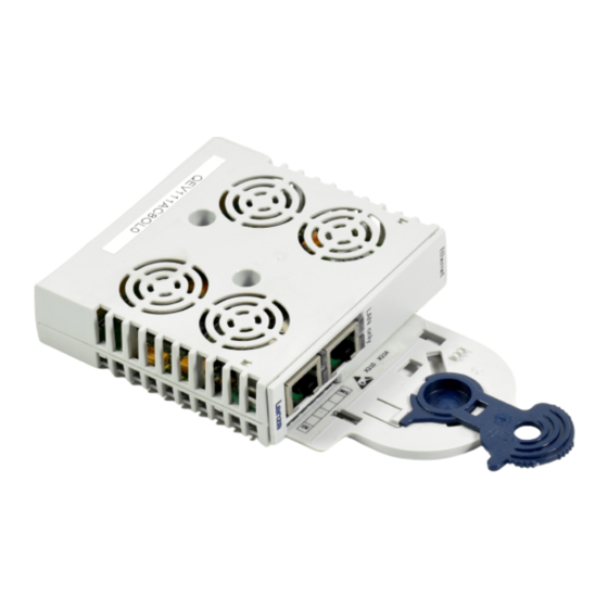
- Page 4 0Fig. 0Tab. 0 Scope of supply Pos. Description Communication module E94AYCEN (Ethernet) Mounting Instructions Connections Pos. Description Ethernet connections X215 Design: RJ45 socket to IEC 60603−7 X216 Status displays Pos. Colour Condition Description Green The communication module is supplied with voltage. The communication module is not accepted by the standard device (see notes given in the documentation for the standard device).
-
Page 5: Table Of Contents
Contents About this documentation ..........Conventions used . -
Page 6: About This Documentation
ƒ information about the mechanical and electrical installation of the communication module; ƒ safety instructions which must be followed; ƒ specifications for the versions of the Lenze standard devices to be used. Validity information The information given in this documentation is valid for the following devices:... -
Page 7: Conventions Used
About this documentation Conventions used Conventions used This documentation uses the following conventions to distinguish between different types of information: Type of information Identification Examples/notes Numbers Decimal separator Point The decimal point is used throughout this documentation. Example: 1234.56 Symbols Page reference Reference to another page with additional information... -
Page 8: Notes Used
About this documentation Notes used Notes used The following pictographs and signal words are used in this documentation to indicate dangers and important information: Safety instructions Structure of safety instructions: Danger! (characterises the type and severity of danger) Note (describes the danger and gives information about how to prevent dangerous situations) Pictograph and signal word Meaning... - Page 9 About this documentation Notes used Application notes Pictograph and signal word Meaning Important note to ensure troublefree operation Note! Useful tip for simple handling Tip! Reference to another documentation EDK94AYCEN DE/EN/FR/ES/IT 6.0...
-
Page 10: Safety Instructions
Safety instructions Safety instructions Danger! Inappropriate handling of the communication module and the standard device can cause serious personal injury and material damage. Observe the safety instructions and residual hazards described in the documentation for the standard device. Stop! Electrostatic discharge Electronic components of the communication module can be damaged or destroyed through electrostatic discharge. -
Page 11: Product Description
The communication module connects Lenze Servo Drives 9400 with the Ethernet communication system. Application as directed The communication module ... ƒ is an accessory which can be used in conjunction with the following Lenze standard devices: Product series Type designation... -
Page 12: Identification
Product description Identification Identification Type HW Ver. MAC ID E94YCEN008 ‚ Type code Product series Device generation Module identification: extension module Module type: communication module Ethernet Hardware version EDK94AYCEN DE/EN/FR/ES/IT 6.0... -
Page 13: Mechanical Installation
Mechanical installation Mechanical installation Note! The Servo Drives 9400 must only be equipped with one Ethernet module, either in module slot MXI1 or in module slot MXI2. Mounting E94YCXX001G EDK94AYCEN DE/EN/FR/ES/IT 6.0... - Page 14 Mechanical installation Dismounting E94AYCXX001H EDK94AYCEN DE/EN/FR/ES/IT 6.0...
-
Page 15: Electrical Installation
Electrical installation Wiring according to EMC Electrical installation Wiring according to EMC In typical systems, the standard Ethernet cable shielding is sufficient. In environments that are subject to strong interferences, the electromagnetic compatibility can be improved through an additional PE connection of the cable shield. Please observe the following notes: 1. -
Page 16: Ethernet Connection
Note! Isolate your Ethernet home network from the operating network for ƒ Ethernet−capable Lenze devices to avoid Ethernet communication errors. More information about this can be found in the Manual "Ethernet in industrial applications". Plug/remove the Ethernet cable plug vertically into/from the socket to ƒ... - Page 17 Electrical installation Ethernet connection Ethernet cable specifications Note! Only use cables complying with the below specifications. Specification of the Ethernet cable Ethernet standard Standard Ethernet (in accordance with IEEE 802.3), 100Base−TX (Fast Ethernet) Cable type S/FTP (Screened Foiled Twisted Pair, ISO/IEC 11801 or EN 50173), CAT 5e Damping 23.2 dB (at 100 MHz and per 100 m)
- Page 18 Electrical installation Ethernet connection Colour code of Ethernet cable Note! Wiring and colour code are standardised in EIA/TIA 568A/568B. You can use 4−pin Ethernet cables in accordance with the industrial standard. The cable type only connects the assigned pins 1, 2, 3 and 6 with each other. E94YCEI004A Fig.
-
Page 19: Voltage Supply
Electrical installation Voltage supply Voltage supply Internal supply The communication module is exclusively internally supplied with voltage by the standard device. Note! With a line topology, data transfer between the Ethernet nodes at interface X215 and the Ethernet nodes at interface X216 will be interrupted when the standard device fails. - Page 20 0Fig. 0Tab. 0 Contenido del suministro Pos. Descripción Módulo de comunicación E94AYCEN (Ethernet) Instrucciones de montaje Conexiones Pos. Descripción Conexiones Ethernet X215 Ejecución: conector RJ45 según IEC 60603−7 X216 Indicaciones de estado Pos. Color Estado Descripción verde encendido El módulo de comunicación está siendo alimentado con voltaje. rojo encendido El módulo de comunicación no es aceptado por el equipo básico...
Need help?
Do you have a question about the L-force Communication Ethernet E94AYCEN and is the answer not in the manual?
Questions and answers