
Related Manuals for ESCO Technologies ETS-LINDGREN BiConiLog 3142E


Summary of Contents for ESCO Technologies ETS-LINDGREN BiConiLog 3142E
- Page 1 Model 3142E BiConiLog ™ Antenna User Manual PN: 399337 Feb, 2021 Rev C ets-lindgren.com...
- Page 2 ETS-Lindgren Inc. reserves the right to make changes to any products herein to improve functioning or design. Although the information in this document has been carefully reviewed and is believed to be reliable, ETS-Lindgren does not assume any liability arising out of the application or use of any product or circuit described herein;...
-
Page 3: Table Of Contents
TABLE OF CONTENTS NOTES, CAUTIONS AND WARNINGS INTRODUCTION Tripod Options � � � � � � � � � � � � � � � � � � � � � � � � � � � � � � � � � � � � � � �6 ETS-Lindgren Product Information Bulletin �... - Page 4 700MHz-800MHz � � � � � � � � � � � � � � � � � � � � � � � � � � � � � � � � � � � � � 21 900MHz-1000MHz � � � � � � � � � � � � � � � � � � � � � � � � � � � � � � � � � � � � � 22 2000MHz-3000MHz �...
-
Page 5: Notes, Cautions And Warnings
NOTES, CAUTIONS AND WARNINGS Note: Denotes helpful information intended to provide tips for better use of the product. CAUTION: Denotes a hazard. Failure to follow instructions could result in minor personal injury and/or property damage. Included text gives proper procedures. WARNING: Denotes a hazard. -
Page 6: Introduction
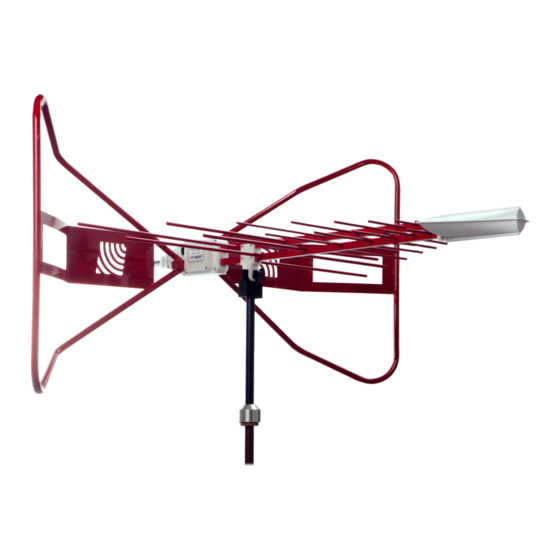
INTRODUCTION The ETS-Lindgren Model 3142E BiConiLog™ Antenna is designed as a dual-purpose antenna that can be used for both immunity and emission testing. From 30 MHz to 6 GHz, the Model 3142E exhibits an average 5.5 dB gain. Applications for the Model 3142E include emissions testing, immunity measurements, and medical equipment testing. -
Page 7: Tripod Options
Tripod Options ETS-Lindgren offers the following non-metallic, non-reflective tripods for use at both indoor and outdoor EMC test sites. • 4-TR Tripod—Constructed of linen phenolic and delrin, designed with an adjustable center post for precise height adjustments. Maximum height is 2.0 m (80.0 in), and minimum height is 94 cm (37.0 in). -
Page 8: Maintenance
MAINTENANCE Replacement and Optional Parts Before performing any maintenance, follow The following are the part numbers for ordering replacement or the safety information optional parts for the Model 3142E. in the ETS-Lindgren Product Information Bulletin included with Part Description Part Number your shipment. -
Page 9: Specifications Electrical Specifications
SPECIFICATIONS Electrical Specifications Frequency Range: 30 MHz–6 GHz Input Impedance (Nominal): 50 Ω VSWR (Average): 2:1 above 50 MHz Maximum Continuous Power Continuous Peak 30 MHz-60 MHz: 500 W 800 W 60 MHz-600 MHz: 1 kW 1.5 kW 600 MHz-1 GHz: 500 W 800 W 1 GHz-6 GHz:... -
Page 10: Assembly
ASSEMBLY Before connecting any components, follow the safety information in the ETS-Lindgren Product Information Bulletin included with your shipment. Model 3142E shown in vertical polarization The Model 3142E BiConiLog™ Antenna is comprised of the following parts: • Antenna • Bowtie elements (2) •... - Page 11 For stability, mount the Model 3142E onto a tripod or tower. See Mounting Instructions on page 19 for the steps to mount the antenna. 2. Slide the narrow end of one of the bowtie elements into the receptacle hole on the antenna balun, and then align the bowtie with the receptacle on the balun.
-
Page 12: Mounting
MOUNTING Contact with any metal or non-metallic structure can capacitively load the antenna, which may cause unrepeatable results. Therefore, make sure that no part of the dipole elements or bowties is in contact with the tripod or tower, particularly in vertically-polarized tests. Where possible, run the feed cable Before connecting any straight one meter or more back from the Model 3142E BiConiLog™... -
Page 13: Using The Stinger To Mount To A Model 2175 Minimast
To attach the included adapters to the Model 3142E: Model 3142E mounted onto 4-TR using included 100989 Polarizing Mounting Adapter and 105861 1/4–20 Thread Insert If required, insert the 1/4–20 thread insert into the mounting adapter. 2. Remove the mounting knob from the mounting bracket on the antenna. 3. - Page 14 Thread the antenna feed or receiving cable through the center of the boom so that the antenna connector emerges a few inches out of the clamp Before connecting any end of the boom. components, follow the safety information in the ETS-Lindgren Product Information Bulletin included with your shipment.
-
Page 15: Additional Mounting Options
5. Tighten the clamp knobs on the boom to secure the antenna into place. Additional Mounting Options 4-TR Mounting Options Following are additional options for mounting the Model 3142E onto an ETS-Lindgren 4-TR tripod. Contact the ETS-Lindgren Sales Department for information on ordering optional mounting hardware. -
Page 16: 7-Tr And Mast Mounting Options
7-TR and Mast Mounting Options The stinger on the Model 3142E enables you to mount to antenna directly to an ETS-Lindgren 7-TR Tripod Positioner. However, following are additional options for mounting the Model 3142E onto an ETS-Lindgren 7-TR Tripod Positioner. Contact the ETS-Lindgren Sales Department for information on ordering... -
Page 17: 2X2 Boom Mounting Options
2X2 Boom Mounting Options Following are additional options for mounting the Model 3142E onto a 2x2 boom. Contact the ETS-Lindgren Sales Department for information on Note: ordering optional mounting hardware. 2x2 boom refers to a typical 2-inch by 2-inch boom. -
Page 18: Typical Data
TYPICAL DATA Typical Antenna Factor and Gain Distance for the ANSI 3-meter and 10-meter calibrations is measured from the antenna midpoint, and for SAE 1-meter calibrations the distance is measured from the antenna tip. Midpoint is defined as half the distance between the small elements and the bowties, which is about 45 cm from the small end tip. -
Page 19: Typical Vswr
Typical VSWR Typical Half Power Beamwidth... -
Page 20: Typical Radiation Patterns
Typical Radiation Patterns 30MHz-50MHz 70MHz-90MHz... -
Page 21: 100 Mhz-200Mhz
100 MHz-200MHz 300MHz-400MHz... -
Page 22: 500Mhz-600Mhz
500MHz-600MHz 700MHz-800MHz... -
Page 23: 900Mhz-1000Mhz
900MHz-1000MHz 2000MHz-3000MHz... -
Page 24: 4000Mhz-5000Mhz
4000MHz-5000MHz 6000MHz... -
Page 25: Typical Cross Polarization
Typical Cross Polarization... -
Page 26: Appendix A: Warranty
APPENDIX A: WARRANTY See the Product Information Bulletin included with your shipment for the complete ETS-Lindgren warranty for your Model 3142E BiConiLog™ Antenna.
Need help?
Do you have a question about the ETS-LINDGREN BiConiLog 3142E and is the answer not in the manual?
Questions and answers