Table of Contents
Advertisement
Quick Links
Advertisement
Table of Contents

Subscribe to Our Youtube Channel
Related Manuals for ESCO Technologies ETS-Lindgren 3301B


Summary of Contents for ESCO Technologies ETS-Lindgren 3301B
- Page 1 Model 3301B Active Rod & Field Antenna User Manual...
- Page 2 ETS-Lindgren L.P. reserves the right to make changes to any products herein to improve functioning or design. Although the information in this document has been carefully reviewed and is believed to be reliable, ETS-Lindgren does not assume any liability arising out of the application or use of any product or circuit described herein;...
-
Page 3: Table Of Contents
Table of Contents Safety Symbol Definitions.........................v General Safety Considerations......................v 1.0 Introduction ..........................7 2.0 Receiving Your Order ........................ 9 2.1 Unpacking and Acceptance ....................9 2.2 Service Procedures........................ 9 3.0 Maintenance ..........................11 3.1 Maintenance Recommendations ..................11 3.2 Replacement and Optional Parts..................11 4.0 Standard Configuration...................... - Page 4 9.0 Theory of Operation......................... 29 9.1 The Rod ..........................29 9.2 The Pre-Amplifier ......................... 30 10.0 The Antenna Factor....................... 33 11.0 Antenna Impulse Response ....................35 11.1 Impulse Characteristics...................... 35 11.2 Pulse Desensitization......................36 11.3 Pulse Charging ........................37 12.0 Calibration Procedure......................39 Appendix A: Warranty Policy for Standard EMCO Brand Products ..........
-
Page 5: Safety Symbol Definitions
Safety Symbol Definitions This product and related documentation must be reviewed for familiarization with safety markings and instructions prior to operation of the product. Safety Symbol Definition REFER TO MANUAL—When the product is marked with this symbol refer to the instruction manual for additional information. If the instruction manual has been misplaced, go to www.ets-lindgren.com downloadable files or contact ETS-Lindgren customer service. - Page 6 This page intentionally left blank.
-
Page 7: Introduction
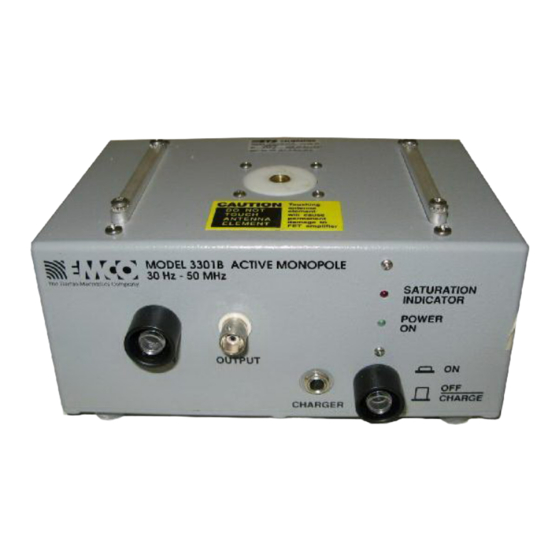
1.0 Introduction The ETS-Lindgren Model 3301B is a broadband, high sensitivity electric-field receiving antenna. The Model 3301B is composed of a monopole rod antenna with a counterpoise, and a broadband, high impedance pre-amplifier. It is designed to provide reception of an electric field in a signal band without tuning or band switching from 30 Hz to 50 MHz. - Page 8 This page intentionally left blank. Introduction...
-
Page 9: Receiving Your Order
2.0 Receiving Your Order 2.1 Unpacking and Acceptance Step 1. Upon delivery of your order, inspect the shipping container(s) for evidence of damage. Record any damage on the delivery receipt before signing it. In case of concealed damage or loss, retain the packing materials for inspection by the carrier. - Page 10 This page intentionally left blank. Receiving Your Order...
-
Page 11: Maintenance
3.0 Maintenance 3.1 Maintenance Recommendations To ensure reliable and repeatable long-term performance, annual recalibration of your antenna by an ETS-Lindgren experienced technician is recommended. Our staff can recalibrate almost any type or brand of antenna. Please call to receive a Service Order Number prior to sending an antenna for calibration. - Page 12 This page intentionally left blank. Maintenance...
-
Page 13: Standard Configuration
4.0 Standard Configuration • Adjustable monopole element • Antenna base with built-in preamplifier and an isolated female BNC connector • Counterpoise (60 cm) • Base drilled to accept EMCO or other tripod mounts with standard ¼” x 20 threads • Batteries and battery charger •... - Page 14 This page intentionally left blank. Standard Configuration...
-
Page 15: Specifications
5.0 Specifications 5.1 Operational Specifications 30 Hz to 50 MHz (maximum usable Frequency Range: bandwidth) The low frequency roll off is switch Low Frequency Roll Off: selectable to be 3 dB down at 22 kHz, 1.9 kHz, or 170 Hz. High Frequency Roll Off: Antenna factor is 3 dB down at 30 MHz See data graphs included with manual. -
Page 16: Table Of Acceptable Pulse Repetition Rates
The saturation indicator will properly indicate saturation for pulsed signals which fall within the following boundaries: 1. The product of the pulse width to pulse Saturation Indicator Impulse Response: repetition rate must be greater than .003. 2. The pulse repetition rate must be less than value listed for the applicable duty cycle. -
Page 17: Mechanical Specifications
The Model 3301B is supplied with two 6V sealed lead-acid batteries. The batteries will Batteries: operate for approximately 10 hours between charges. 115/230 VAC 50/60 Hz switch selectable, Battery Charger: IEC input, two-stage battery charger with fast and trickle charge modes. •... - Page 18 This page intentionally left blank. Specifications...
-
Page 19: Principles Of Operation
6.0 Principles of Operation 6.1 Description The ETS-Lindgren Model 3301B electric field receiving antenna is composed of three principal sections: a sensing rod, a ground plane or counterpoise, and a broadband, high input impedance pre-amplifier. The rod and counterpoise function together as an electrically short antenna over ground plane. -
Page 20: Internal Options
ATURATION NDICATOR The Saturation indicator is located above the power indicator. Readings should not be taken when the unit indicates it is in saturation. If this occurs, input to the unit should be reduced by placing the unit in the low gain mode or by switching in internal attenuation. -
Page 21: Factory Settings
The antenna rod terminal is directly connected to the high impedance gate of a field effect transistor. Do not lift the antenna by the rod or touch it before properly grounding out to the unit case. Accumulated static charge on test personnel may damage the FET. -
Page 22: Proper Selection Of Internal Attenuation
If both roll off switches are simultaneously set in the on position, the low frequency 3 dB roll of point will be approximately 23 kHz. 6.3.2 Proper Selection of Internal Attenuation When dealing with CW type signals, no attenuation is needed to measure field strengths below 0.7 V/m. -
Page 23: Power Circuitry
7.0 Power Circuitry The Model 3301B is powered by two 6 VDC sealed lead-acid batteries. A battery charger is supplied with the unit. The battery charging port of the front of the unit allows for easy recharging of the unit. Two internal fuses protect the unit from unintentional shorting. -
Page 24: Specifications
The battery charger is protected against overcurrent by a 200 mA 250 VAC time-delay fuse. If it becomes necessary to replace the fuse, use a fuse of the same type and rating to maintain safe operations. The fuse is accessible by removing the two Phillips head screws on the underside of the unit. - Page 25 2. Locate the two fuses in their holders mounted on the circuit board, and replace the fuses. 3. Replace the bottom panel of the unit and reinstall the screws. Power Circuitry...
- Page 26 This page intentionally left blank. Power Circuitry...
-
Page 27: Setup And Use
8.0 Setup and Use The Model 3301B is designed for ease of use, and is designed for five accurate reading types in a variety of test environments. However, precision measurements require an understanding of the test parameters that will adversely affect test results. No single test instrument can insure accurate results. -
Page 28: High Sensitivity Readings
8.2 High Sensitivity Readings The Model 3301B is optimized to facilitate extremely sensitive readings. For best performance, all internal attenuation should be off. The gain switch should be placed in the low gain setting. The noise limiting factor on the Model 3301B is the high front end impedance presented to the FET. -
Page 29: Theory Of Operation
9.0 Theory of Operation 9.1 The Rod There are three factors of primary interest in understanding a rod antenna. These factors are its effective electrical length, the impedance it presents to the measurement system, and the interaction of the rod with the ground. The discussion here will contain itself to discussing an electrically short antenna element. -
Page 30: The Pre-Amplifier
Finally, the interaction of the rod with the ground must be understood. The theoretical understanding of the rod assumes that it operates in reference to an infinite ground at 0 Volt potential. The closer the test situation is to this scenario the more accurate will be the readings. - Page 31 It is the output impedance which determines the effective low frequency cutoff of the unit. The Model 3301B is still usable at an extremely low 30 Hz. In fact, artificial limiting was introduced to protect the unit in situations where overloading from power frequencies would be a problem.
- Page 32 high. However, the amplifier is being called upon to amplify signals at many frequencies simultaneously. In the time domain, the amplifier would be seen to be presented with quite a large power demand. The result is that impulsive signals appear to saturate the amplifier at must lower signal levels. The Model 3301B has been measured to begin going non-linear at 64 dBuV/m/MHz.
-
Page 33: The Antenna Factor
10.0 The Antenna Factor The antenna factor data provided with the unit is simply a ratio of the field strength presented to the unit to the voltage output from the unit at that field strength. By adding the antenna factor to a given output, the field strength may be derived. - Page 34 This page intentionally left blank. The Antenna Factor...
-
Page 35: Antenna Impulse Response
11.0 Antenna Impulse Response The Model 3301B is designed and optimized for the measurement of CW type signals. However, this unit is fully capable of dealing accurately with impulsive type signals, with some special considerations. This section guides the user who intends to use the Model 3301B to measure impulsive signals. -
Page 36: Pulse Desensitization
In the same way, the antenna will not efficiently pass spectral components that fall below its bandwidth. For the Model 3301B, the selected low frequency roll off will determine how wideband the response is. The very low frequency components basically describe the flat top and bottom of the time domain pulse. So, when the waveform is band limited by the antenna, the resulting waveform will have a decay constant returning the output to ground rather than maintaining a flat topped pulse. -
Page 37: Pulse Charging
begins to discharge through its resistance to ground. If the PRF is slow enough so that the capacitor is fully discharged before the next pulse arrives, it may never trigger the indicator. The antenna amplifier, on the other hand, must satisfy the instantaneous energy demand. - Page 38 This page intentionally left blank. Antenna Impulse Response...
-
Page 39: Calibration Procedure
12.0 Calibration Procedure ETS-Lindgren recommends the equivalent capacitance method of calibration for the Model 3301B active rod antenna. To check the calibration, a Model 3301B calibration test fixture is required. This fixture contains a resistive T and a capacitor. The T allows for accurate reading of the input to the fixture. The capacitor feeds the amplifier through the same impedance as the 41”... - Page 40 This page intentionally left blank. Calibration Procedure...
-
Page 41: Appendix A: Warranty Policy For Standard Emco Brand Products
Appendix A: Warranty Policy for Standard EMCO Brand Products COPE AND URATION OF ARRANTIES Seller warrants to Buyer that the Standard EMCO Brand Products Excluding 5211 & 5220 be (1) free from defects in material, manufacturing workmanship, and title, and (2) conform to the Seller’s applicable product descriptions and specifications, if any, contained in or attached to Seller’s quotation. -
Page 42: Buyer's Remedies
Warranty coverage does not include any defect or performance deficiency (including failure to conform to product descriptions or specifications) which results, in whole or in part, from (1) negligent storage or handling of the product by Buyer, its employees, agents, or contractors, (2) failure of Buyer to prepare the site or provide an operating environmental condition in compliance with any applicable instructions or recommendations of Seller, (3) absence of any product, component, or accessory recommended by Seller but omitted at Buyer’s direction, (4) any design, specification, or... - Page 43 MADE BY BUYER EXCEED THE PURCHASE PRICE OF THE PRODUCT IN RESPECT OF WHICH DAMAGES ARE CLAIMED This agreement shall be construed in accordance with laws of the State of Illinois In the event that any provision hereof shall violate any applicable statute, ordinance, or rule of law, such provision shall be ineffective to the extent of such violation without invalidating any other provision hereof.
- Page 44 This page intentionally left blank. Warranty Policy for Standard EMCO Brand Products...
-
Page 45: Appendix B: European Community Declaration Of Conformity
Appendix B: European Community Declaration of Conformity The EC Declaration of Conformity is the method by which EMC Test Systems, L.P. declares that the equipment listed on this document complies with the EMC and Low- voltage Directives. Factory Issued by EMC Test Systems, L.P. - Page 46 This page intentionally left blank. European Community Declaration of Conformity...
-
Page 47: Appendix C: Data And Illustrations
Appendix C: Data and Illustrations ERIODIC ECTANGULAR ULSE RAIN PECTRUM OF ECTANGULAR ULSE Amplitudes and phases of an infinite number of harmonics are required to fully describe the envelope. Data and Illustrations... -
Page 48: Altering Pulse Width / Pulse Repetition Rate
LTERING ULSE IDTH ULSE EPETITION The following figures A–D depict the effect of altering either the pulse width or pulse repetition rate. A narrow pulse width (A, C) spreads the pulse energy over a wider frequency band. Wider pulses (B, D) cause narrower lobes. A low pulse repetition rate (A, B) creates widely spaced spectral lines. -
Page 49: Active Electric Field Antenna Calibration Fixture
CTIVE LECTRIC IELD NTENNA ALIBRATION IXTURE Data and Illustrations... -
Page 50: Active Rod Antenna Calibration Setup
CTIVE NTENNA ALIBRATION ETUP Data and Illustrations... -
Page 51: Typical Curves-Minimum Discernible Signal At Various Bandwidths
—M YPICAL URVES INIMUM ISCERNIBLE IGNAL AT ARIOUS ANDWIDTHS Data and Illustrations... -
Page 52: Typical Attenuation Effect For Switches 1 And 2
YPICAL TTENUATION FFECT FOR WITCHES Data and Illustrations... -
Page 53: Typical Roll Off Curves For Switches 3 And 4
YPICAL URVES FOR WITCHES Data and Illustrations... -
Page 54: Typical Roll Off Curves-41" Rod Antenna, 0 Db Attenuation
—41” R YPICAL URVES NTENNA TTENUATION Generator output 250 mV Data and Illustrations... -
Page 55: Typical Roll Off Curves-41" Rod Antenna, 10 Db Attenuation
—41” R , 10 YPICAL URVES NTENNA TTENUATION Generator output 250 mV Data and Illustrations... -
Page 56: Typical Roll Off Curves-41" Rod Antenna, 30 Db Attenuation
—41” R , 30 YPICAL URVES NTENNA TTENUATION Generator output 8000 mV Data and Illustrations...
Need help?
Do you have a question about the ETS-Lindgren 3301B and is the answer not in the manual?
Questions and answers