Table of Contents
Advertisement
Quick Links
Advertisement
Table of Contents

Related Manuals for Kikusui PAD-LA Series


Summary of Contents for Kikusui PAD-LA Series
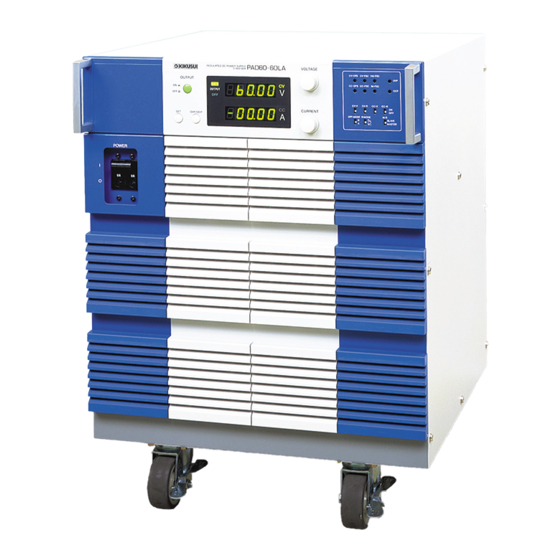
- Page 1 Part No. Z1-002-712, I0041001 May 2021 OPERATION MANUAL Regulated DC Power Supply PAD-LA Series TYPE III PAD 16 -100LA PAD 36 -60LA PAD 60 -35LA PAD 72 -30LA PAD 110 -20LA PAD 250 -8LA TYPE IV PAD 36-100LA PAD 60 -60LA...
- Page 2 If you find any incorrectly arranged or missing pages in this manual, they will be replaced. If the manual it gets lost or soiled, a new copy can be provided for a fee. In either case, please contact Kikusui distributor/ agent, and provide the “Kikusui Part No.”...
- Page 3 Green/Yellow (GND) Green or Green/Yellow (GND) Plug for USA Plug for Europe Plug for China 2P plug NEMA5-15 CEE7/7 GB1002 JIS C 8303 Provided by Kikusui distributor/agent Kikusui agents can provide you with suitable power cord. For further information, contact Kikusui distributor/agent. PAD-LA...
- Page 4 PAD-LA...
- Page 5 Safety Symbols For the safe use and safe maintenance of this product, the following sym- bols are used throughout this manual and on the product. Understand the meanings of the symbols and observe the instructions they indicate (the choice of symbols used depends on the products). Indicates that a high voltage (over 1000 V) is used here.
-
Page 6: Safety Precautions
Safety Precautions The following safety precautions must be observed to avoid fire hazard, electrical shock, accidents, and other failures. Keep them in mind and make sure that all of them are observed properly. Using the product in a manner that is not specified in this manual may impair the protection functions provided by the product. - Page 7 • To maintain performance and safe operation of the product, it is recommended that periodic maintenance, checking, cleaning, and calibration be performed. Service • Internal service is to be done by Kikusui service engineers. If the product must be adjusted or repaired, contact Kikusui distributor/agent. PAD-LA...
- Page 8 Arrangement of this manual This Operation Manual is made up of the following sections. Preface Provides a brief descriptions of the product and specifies its features. Chapter 1 Setup This chapter describes the necessary procedure from unpacking to preparation before use. Chapter 2 Before Using the Power Supply Before using the power supply, users are requested to thoroughly understand the fol-...
-
Page 9: Table Of Contents
Contents Safety Symbols ____________________________________________ III Safety Precautions _________________________________________ IV Preface _________________________________________________ P-1 Chapter 1 Setup _________________________________________ 1-1 Checking the Package Contents - - - - - - - - - - - - - - - - - - - - - - - - - - - - - 1-2 Precautions Concerning Installation Location - - - - - - - - - - - - - - - - - - - 1-4 Precautions When Moving the Power Supply... - Page 10 4.3.3 Connection and Setup for Output Current Control Using an External Re- sistor (CC-R) - - - - - - - - - - - - - - - - - - - - - - - - - - - - - - - - - - - 4-16 4.3.4 Connection and Setup for Output Current Control Using an External Volt- age (CC-V)
-
Page 11: Preface
• PAD250-15LA Product Overview The PAD-LA series is a regulated DC power supply with a constant voltage/current automatic crossover function utilizing a switching regulator system. The series reg- ulator system equipped with phase-control preregulators achieves stable output with small amount of noise. The power supply can be used in a wide range of applica- tions including use in the laboratory for experiment equipment, for tests on mass production lines, and for aging tests. - Page 12 Controllers. NOTE • Since the PAD-LA series power supplies use a phase control circuit for the prereg- ulator, pulse-shaped noise is superimposed on the output signal. The noise level is suppressed to few hundred mV, but this may constitute a problem depending on the application.
- Page 13 Required blank panel width Blank panel 1U or greater BP191(-M) BP1H(-M) Blank panel 1U or greater BP191(-M) BP1H(-M) 1U or Blank panel greater BP191(-M) BP1H(-M) When one power supply is rack mounted When two power supplies are rack mounted *1: 1U; JIS standard: 50 mm, EIA standard: 44.45 mm Fig.
- Page 14 Bracket KRB11-PAD KRB500-PAD NOTE • The PAD-LA type IV model, it is not necessary to install blank panels when the power supplies are rack mounted. For details, contact your Kikusui agent or distributor. Bracket KRB11-PAD Bracket KRB500-PAD Unit: mm Fig.P-1...
-
Page 15: Chapter 1 Setup
Chapter 1 Setup This chapter describes the necessary procedure from unpacking to preparation before use. PAD-LA Setup 1-1... -
Page 16: Checking The Package Contents
When you receive the product, check that all accessories are included and that the accessories have not been damaged during transportation. If any of the accessories are damaged or missing, contact your Kikusui agent or dis- tributor. The Type III model includes the following accessories. - Page 17 The Type IV model includes the following accessories. Operation manual (1 pc.) Guard cap (2 pcs.) GP01-PMC [83130] Do not attach the sticker CAUTION where the intake and exhaust ports of the power supply will be obstructed. Power cord (1 set) Weight sticker (1 pc.) [91-87-6316] [A8-000-017]...
-
Page 18: Precautions Concerning Installation Location
However, operation in such environments may be possible through alteration. If you wish to use the power supply in such environments, consult your Kikusui agent or distributor. ■ Do not place the power supply in a dusty location. - Page 19 ■ Do not use the power supply in a location subject to strong magnetic or electric fields. The power supply may malfunction and cause electric shock or fire. ■ Do not use the product near highly sensitive measuring instruments or transceivers. The noise generated by the power supply may affect them.
- Page 20 Using the Stopper of Type IV model Fixing stoppers are attached to the front caster on bottom. Moving down strongly fixing stoppers with your foot toward the ON until stop. NOTE • These Stoppers are temporary. When fix certainly, power supplies are rack mounted For details, see Page P-4 "Rack mounting option of the type IV model".
-
Page 21: Precautions When Moving The Power Supply
Precautions When Moving the Power Supply When moving or transporting the power supply to the installation site, observe the following precautions. ■ Turn off the POWER switch. Moving the power supply with the power on may result in electric shock or damage. ■... -
Page 22: Connecting The Power Cord
Connecting the Power Cord WARNING • Connection of the AC power cord to the switchboard must be carried out by qualified personnel. • To prevent electric shock, turn off the switch on the switchboard (to cut off the power feed from the switchboard) and then connect the AC power cord. - Page 23 N (white) GND (green) L (black) AC INPUT terminal block (Terminal screw diameter: M6) Tightening torque: 3.0 N・m Clamper (Attachment screw diameter: M4) Terminal cover (Attachment screw diameter: M3) Fig. 1-5 AC INPUT terminal block connection of Type III model Connection procedure of Type IV model Connect the power cord provided to the AC INPUT terminal block and fix the cables securely by clamper as shown in Fig.
-
Page 24: Grounding
Grounding WARNING • Electric shock may occur, if proper grounding is not furnished. Be sure to ground the power supply to prevent accidents resulting in death or injury. • Connect the ground terminal to an adequate earth ground. CAUTION • If you do not ground the power supply, malfunction may occur due to exter- nal noise, or the noise generated by the power supply may become large. -
Page 25: Chapter 2 Before Using The Power Supply
Chapter 2 Before Using the Power Supply Before using the power supply, users are requested to thoroughly understand the fol- lowing matters. PAD-LA Before Using the Power Supply 2-1... -
Page 26: Inrush Current
Inrush Current An inrush current indicated below may flow when the POWER switch is turned on. If you are planning to use several power supplies in a system and turn on their POWER switches simultaneously, check that the AC power source or the switch- board is of sufficient capacity. -
Page 27: When The Load Current Has Peaks Or Is Pulse-Shaped
2.3.1 When the Load Current Has Peaks or Is Pulse-shaped Even when the power supply indicates a current less than the output current limit, the peak value may actually exceed the limit. This is due to the fact that the meter indi- cates mean values. -
Page 28: When The Load Has Accumulated Energy Such As Batteries
2.3.3 When the Load Has Accumulated Energy such as Bat- teries Connecting a load with accumulated energy, such as a battery, to the power supply may cause large current to flow from the load into the capacitor inside the power supply through the protection diode of the internal output control circuit. -
Page 29: Cv Power Supply And Cc Power Supply
CV Power Supply and CC Power Supply The power supply is capable of both constant voltage and constant current opera- tion. This section describes these operations. An ideal constant voltage power supply has zero output impedance at all frequencies and maintains a constant voltage against all types of load current variations. An ideal constant current power supply has infinite output impedance at all frequencies and maintains constant current against load resistance variations. - Page 30 power supply automatically switches from the constant voltage to constant current operation to prevent an overcurrent from flowing. (The point at which the operation mode switches is called the “crossover point”.) If the current limit is raised in this condition, the power supply returns to the previous constant voltage operation, allowing you to increase the output voltage further.
-
Page 31: Protective Circuit
Protective Circuit It is important to remember that a regulated power supply handles “power.” Acci- dents due to malfunction or erroneous operation of the power supply can cause the operation of an entire system to halt or cause damage to the power supply unit and load or in the worst case a fire. -
Page 32: Output Terminal Isolation
Output Terminal Isolation ■ The output terminal is insulated The output terminal of the power supply is insulated from the chassis. By connect- ing the GND wire of the power cord to the ground terminal of the switchboard, the chassis of the power supply is set to ground potential as shown in Fig. 2-8. ■... - Page 33 ■ When the negative output terminal is connected to the chassis terminal As shown in Fig. 2-9, the negative output terminal will be at ground potential. Con- sequently, the cable and load that are connected to the output terminal (including the sensor terminal) must have an insulation capacity that is greater than the maximum output voltage of the power supply with respect to the chassis.
- Page 34 In summary, connect either output terminal to the chassis terminal for safety reasons unless your application requires the output terminal to be floating. Moreover, the output ripple may become large if the output terminal is not connected to the chassis terminal.
-
Page 35: Chapter 3 Basic Operation
Chapter 3 Basic Operation This chapter describes the basic operations that you can perform from the front panel. PAD-LA Basic Operation 3-1... -
Page 36: Turning On The Power
Turning On the Power Overview of the procedure Turn off the OUTPUT switch before turning on the POWER switch. Turn on the power without connecting the load. Preparation Main operation Power supply behavior Output voltage can be Operate the switch and Turn on the POWER specified. - Page 37 Power up procedure Turn off the POWER switch. Turn off the OUTPUT switch. Turn off all control switches or set them to the bottom side. Check that the power cord is correctly connected. Turn on the switch of the switchboard supplying power to the power supply.
-
Page 38: Basic Operation
Basic Operation The power supply has two modes: constant voltage operation (CV) mode and con- stant current operation (CC) mode. Before using the power supply, check which mode is to be used, and follow the procedure for the corresponding operation mode. 3.2.1 Setting the OVP (Overvoltage Protection) and OCP (Overcurrent Protection) Trip Points... - Page 39 Setting the OVP/OCP trip point Turn off the OUTPUT switch. Turn on the POWER switch. While holding down the OVP/OCP switch, turn the OVP variable resistor or the OCP variable resistor using a Phillips screwdriver to the desired value. While the OVP/OCP switch is held down, the voltmeter and ammeter indicate the current OVP trip point and the current OCP trip point, respectively.
- Page 40 Checking the OVP/OCP operation After setting the OVP/OCP trip point, be sure to check that OVP or OCP operates. ■ Checking the OVP operation Turn off the OUTPUT switch. Turn on the POWER switch. Turn the VOLTAGE knob counterclockwise all the way. Turn the CURRENT knob two to three times in the clockwise direction.
-
Page 41: Using The Power Supply As A Constant Voltage Power Supply
3.2.2 Using the Power Supply as a Constant Voltage Power Supply Overview of the procedure Set the output voltage using the VOLTAGE knob. Set the appropriate current for the load using the CURRENT knob. Preparation Main operation Power supply behavior The voltmeter and Set the current and Turn off the OUTPUT... -
Page 42: Using The Power Supply As A Constant Current Power Supply
3.2.3 Using the Power Supply as a Constant Current Power Supply Overview of the procedure Set the output current using the CURRENT knob. Set the appropriate voltage for the load using the VOLTAGE knob. Preparation Main operation Power supply behavior The ammeter and volt- Set the voltage and Turn off the OUTPUT... -
Page 43: Connecting The Load
For measures against noise in the load cables, installing the positive and negative output lines side by side or bundling them together is more effective against unwanted noise. The Kikusui-recommended currents shown in Table 3-1 are allow- able current values that have been reduced in consideration of the potential bundling of wires. -
Page 44: Connecting To The Output Terminals
Table 3-1 Nominal cross-sectional area of wires and allowable currents Nominal Cross- (Reference Cross- Allowable Current(*) Kikusui-Recom- Sectional Area Sectional Area) mended Current (Ta = 30 °C) (2.08) (3.31) (5.26) (8.37) (13.3) (21.15) (33.62) (42.41) (53.49) (67.43) (85.01) (107.2) *Excerpts from Japanese laws related to electrical equipment... - Page 45 Connection procedure of Type III model Remove the terminal cover. (See Fig. 3-3 for the following procedure.) Loosen the screws fixing the wire hole cover and move the cover all the way to the left. Attach the load cables. Run the cable vertically. Move the wire hole cover to the right so that it touches the cables and fix it in place by tightening the screws.
- Page 46 Connection procedure of Type IV model Remove the terminal cover. (See Fig. 3-4 for the following procedure.) Attach the load cables. Run the cable vertically. Attach the terminal cover. Terminal cover M8 screw (Attachment screw Tightening torque: 11.22 N•m diameter: M3) Fig.
-
Page 47: Fixing The Output Setting
Fixing the Output Setting The power supply comes with guard caps for fixing or partially fixing the VOLT- AGE knob or CURRENT knob mechanically. Use them when you wish to prevent changing the output setting inadvertently. Using guard caps Turn off the OUTPUT switch. Turn on the POWER switch. - Page 48 Fixed Pierce this surface Partially fixed using a screwdriver. Perform the work on a hard surface such as a hard table. Fig. 3-5 Attaching the guard cap Fitting Fig. 3-6 Fitting inside the bearing Reattaching the preset knob There is a groove on the axis of the variable resistor. The knob must be attached so that it engages with this groove.
-
Page 49: Chapter 4 Application Operation
Chapter 4 Application Operation This chapter describes remote sensing, external output control, parallel operation, and series operation using the control terminal block on the rear panel. PAD-LA Application Operation 4-1... -
Page 50: Remote Sensing
Remote Sensing The remote sensing function is used to reduce the influence of voltage drops due to the load cable resistance and stabilize the output voltage across the load. The remote sensing function of this power supply can compensate up to approximately 0.6 V for a single line. - Page 51 Table 4-1 Remote sensing connection check list Item Description For sensing wires, use cables with a higher voltage rating than the isolation voltage of the power supply. For details, see section 2.6, “Output Terminal Iso- lation.” Insulation When using shielded wires, protect the uncovered section of the shielded wire by using insulation tubes with a withstand voltage greater than the isolation voltage of the power supply.
- Page 52 NOTE • When using the PAD16-100LA around the rated output voltage, use a load cable with a large cross-sectional area. To achieve 16 V at the load end, be sure that the one-way voltage drop in the load wire is less than or equal to 0.24 V. If approximately 0.6 V of compensation is per- formed on one way, the voltage at the load end will be less than or equal to the rated voltage.
-
Page 53: Control Terminal Block
Control Terminal Block The control terminal block on the rear panel can be used to perform the following operations. • Control the output using an analog signal • Control the output ON/OFF using an external contact • Control the output shutdown using an external contact •... - Page 54 Table 4-2 Control terminal block arrangement Input/ Terminal Signal Output/ Description Panel Marking Common 1 SERIES SIG OUT Output Signal for master-slave series connection SER OUT 2 A COM Common Control signal for output voltage using an external voltage 3 CV V CONT Input 4 CV R CONT OUT Output...
- Page 55 Control terminal block connection procedure WARNING • Possible electric shock. May lead to death or injury. Turn off the POWER switch when wiring the control terminal block. • Electric shock or damage to the internal circuit may result if wire scraps protruding from the control terminal block come in contact with the chassis.
-
Page 56: Analog Remote Control
Analog Remote Control This section describes remote control using an analog signal and external contact. Table 4-3 Output voltage control using an external resistor (CV-R) Output voltage control using an external voltage (CV-V) Output current control using an external resistor (CC-R) Output current control using an external voltage (CC-V) OUTPUT ON/OFF using an external contact Output shutdown using an external contact (TRIP) - Page 57 ■ Mode in which the output is controlled using an external resistor You can use one of the following two modes when controlling the output voltage or output current using an external resistor. Eo max 10 k MAX OUT mode Io max Mode in which the output voltage or output current increases as the resistance increases (0 to the rated...
-
Page 58: Connection And Setup For Output Voltage Control Using An External Resistor (Cv-R)
4.3.1 Connection and Setup for Output Voltage Control Using an External Resistor (CV-R) This mode is used to control the output voltage using an external resistor (Rext) in the range of 0 to approx. 10 kΩ. Table 4-4 CV-R switch setting Switch Setting Description... - Page 59 Table 4-5 CV-R connection checklist Item Description The insulation of the Rext and the cable connecting to it should be greater than the iso- lation voltage of the power supply. For details, see section 2.6, “Output Terminal Isola- tion.” Insulation When using shielded wires, protect the uncovered section of the shielded wire by using insulation tubes with a withstand voltage greater than the isolation voltage of the power supply.
-
Page 60: Connection And Setup For Output Voltage Control Using An External Voltage (Cv-V)
4.3.2 Connection and Setup for Output Voltage Control Using an External Voltage (CV-V) This mode is used to control the output current using an external voltage (Vext) in the range 0 to approx. 10 V. Table 4-7 CV-V switch setting Switch Setting Description... - Page 61 Table 4-8 CV-V connection checklist Item Description The insulation of the Vext and the cable connecting to it should be greater than the iso- lation voltage of the power supply. For details, see section 2.6, “Output Terminal Isola- tion.” Insulation When using shielded wires, protect the uncovered section of the shielded wire by using insulation tubes with a withstand voltage greater than the isolation voltage of the power supply.
- Page 62 ■ CV-V control source The control source for CV-V control is an external voltage. The control source when combined with another analog control is indicated below. Table 4-9 Combination of analog control and control source Control Source for Output Control Source for Output Combination Voltage Current...
- Page 63 Connecting the shield to the Vext side CAUTION • Possible damage to internal circuit due to short circuit. If you are connect- ing the shield to the Vext side, do not connect the shield to the positive out- put terminal of the power supply. When using shielded wires, some of Vexts may require that the shield be connected to the Vext.
-
Page 64: Connection And Setup For Output Current Control Using An External Resistor (Cc-R)
4.3.3 Connection and Setup for Output Current Control Using an External Resistor (CC-R) This mode is used to control the output current using an external resistor in the range of 0 to approx. 10 kΩ. Table 4-10 CC-R switch setting Switch Setting Description... - Page 65 Table 4-11 CC-R connection checklist Item Description The insulation of the Rext and the cable connecting to it should be greater than the iso- lation voltage of the power supply. For details, see section 2.6, “Output Terminal Isola- tion.” Insulation When using shielded wires, protect the uncovered section of the shielded wire by using insulation tubes with a withstand voltage greater than the isolation voltage of the power supply.
-
Page 66: Connection And Setup For Output Current Control Using An External Voltage (Cc-V)
4.3.4 Connection and Setup for Output Current Control Using an External Voltage (CC-V) This mode is used to control the output current using an external voltage in the range of 0 to approx. 10 V. Table 4-13 CC-V switch setting Switch Setting Description... - Page 67 Table 4-14 CC-V connection checklist Item Description The insulation of the Vext and the cable connecting to it should be greater than the iso- lation voltage of the power supply. For details, see section 2.6, “Output Terminal Isola- tion.” Insulation When using shielded wires, protect the uncovered section of the shielded wire by using insulation tubes with a withstand voltage greater than the isolation voltage of the power supply.
- Page 68 ■ CC-V control source The control source for CC-V control is an external voltage. The control source when combined with another analog control is indicated below. Table 4-15 Combination of analog control and control source Control Source for Output Control Source for Output Combination Current Voltage...
- Page 69 Connecting the shield to the Vext side CAUTION • Possible damage to internal circuit due to short circuit. If you are connect- ing the shield to the Vext side, do not connect the shield to the positive out- put terminal of the power supply. When using shielded wires, some of Vexts may require that the shield be connected to the Vext.
-
Page 70: Connection And Setup For Output On/Off Control Using An External Contact
4.3.5 Connection and Setup for OUTPUT ON/OFF Control Using an External Contact This mode is used to control the output on/off status using an external contact. One of two modes can be selected. Table 4-16 OUTPUT ON/OFF control mode using an external contact Control Mode Description A mode... - Page 71 Table 4-18 OUTPUT ON/OFF switch setting Switch Setting Description CV-V OFF/ON When controlling the output voltage externally, turn on CV-V or CV-R. CV-R OFF/ON CC-V OFF/ON When controlling the output current externally, turn on CC-V or CC-R. CC-R OFF/ON Selects A mode (output turns OFF when the external contact is closed) OFF-MODE Selects B mode (output turns ON when the external contact is closed) R-MODE...
- Page 72 Table 4-19 OUTPUT ON/OFF connection checklist Item Description The insulation of the external contact (S) and the cable connecting to it should be greater than the isolation voltage of the power supply. For details, see section 2.6, “Out- put Terminal Isolation.” Insulation When using shielded wires, protect the uncovered section of the shielded wire by using insulation tubes with a withstand voltage greater than the isolation voltage of the power...
-
Page 73: Connection And Setup For Output Shutdown (Trip) Control Using An External Contact
4.3.6 Connection and Setup for Output Shutdown (TRIP) Control Using an External Contact The output can be tripped using an external contact such as when abnormalities occur. When the external contact is closed, the POWER switch is turned off. When turning the POWER back on, wait approximately 60 s, remove the cause that caused the external contact to close, and then turn on the POWER switch. -
Page 74: Master-Slave Parallel Operation
CAUTION • Connecting power supplies with different rated outputs can cause a mal- function. Only PAD-LA series power supplies with the same rated output voltage and rated output current can be connected in parallel. • Be sure to use master-slave parallel operation when using parallel opera- tion. - Page 75 Connection and setup procedure Turn off the OUTPUT switches of all power supplies. Turn off the POWER switches of all power supplies. Choose the power supply that will be the master. Set the OVP (overvoltage protection) trip point on the master and slave power supplies.
- Page 76 10 11 12 13 14 15 16 17 18 – OUTPUT PARALLEL Slave 2 MONITOR ALARM TRIP DC OUTPUT 25 26 27 28 29 30 31 32 Remove the grounding short bar. 10 11 12 13 14 15 16 17 18 –...
- Page 77 Table 4-22 Master-slave parallel operation wiring list Wiring Load Master Slave 1 Slave 2 Note Name Terminal Terminal Terminal Terminal Control wire Terminal 17 Terminal 15 LC1S (MASTER) (SLAVE1) Terminal 16 Terminal 14 LC1C (COM) (COM) Terminal 28 Terminal 26 LC2S (ALM IN) (ALM OUT 1)
- Page 78 Table 4-23 Master-slave parallel operation connection checklist Item Description Use wires with sufficient current capacity with respect to the rated current. Use wires of Load wire the same length and thickness for connecting each power supply to the load. Otherwise, the output current of each power supply may not match.
- Page 79 Starting the parallel operation Overview of the procedure The POWER switch and OUTPUT switch on the master and slave power supplies must be turned on in a certain order. Preparation Operation Operation First: Turn on the First: Turn on the OUT- POWER switch PUT switches of of the master...
- Page 80 Stopping the parallel operation Overview of the procedure The POWER switch and OUTPUT switch on the master and slave power supplies must be turned off in a certain order. Preparation Operation Operation First: Turn off the First: Turn off the OUTPUT switch POWER switches of the master...
-
Page 81: Master-Slave Series Operation
CAUTION • Only PAD-LA series power supplies with the same rated output voltage and rated output current can be connected in series. Connecting power supplies with different rated outputs can cause a malfunction. - Page 82 ■ OVP/OCP trip point setting during Master-Slave series operation When using series operation, be sure to set the OVP (overvoltage protection) trip point on the slave power supplies in addition to the master power supply. Set the OVP trip point of the slave power supply approximately 1 % higher than the OVP trip point setting of the master power supply.
- Page 83 Connection and setup procedure Turn off the OUTPUT switches of all power supplies. Turn off the POWER switches of all power supplies. Choose the power supply that will be the master. Set the OVP/OCP trip point on the master and slave power supplies. Set the OVP/OCP trip point of the slave power supply approximately 1 % higher than the OVP/OCP trip point setting of the master power supply.
- Page 84 When using remote sensing, remove the sensing short bar. 10 11 12 13 14 15 16 17 18 – OUTPUT PARALLEL Slave 2 MONITOR ALARM TRIP DC OUTPUT 25 26 27 28 29 30 31 32 10 11 12 13 14 15 16 17 18 –...
- Page 85 Table 4-25 Master-slave series operation wiring list Wiring Load Master Slave 1 Slave 2 Note Name Terminal Terminal Terminal Terminal Control wire Terminal 1 Terminal 3 (SER OUT) (CV-V) Terminal 1 Terminal 3 (SER OUT) (CV-V) Wire only when a Positive out- LC1 shield LC2 shield...
- Page 86 Starting the series operation Overview of the procedure The POWER switch and OUTPUT switch on the master and slave power supplies must be turned on in a certain order. Preparation Operation Operation First: Turn on the First: Turn on the OUT- POWER switch PUT switches of of the master...
- Page 87 Stopping the series operation Overview of the procedure The POWER switch and OUTPUT switch on the master and slave power supplies must be turned off in a certain order. Preparation Operation Operation First: Turn off the First: Turn off the OUTPUT switch POWER switches of the master...
-
Page 88: External Monitoring Of The Output
External Monitoring of the Output Output voltage and output current monitor outputs are provided on the control ter- minal block. Table 4-27 Monitor output of output voltage and output current Terminal Signal Name Operation V MONITOR COM Common terminal of the output voltage monitor Output voltage monitor output V MONITOR OUT 0 V to approx. -
Page 89: Chapter 5 Names And Functions Of Controls
Chapter 5 Names and Functions of Controls This chapter describes the names and functions of switches, displays, terminals, and other parts of the front panel and rear panel. Read this chapter to learn about the details of the (alert) marks inscribed on the panel. -
Page 90: Front Panel
REGULATED DC POWER SUPPLY VOLTAGE 0--16 V 100A CV--OFS CV--FSC VM--FSC OUTPUT CC--OFS CC--FSC IM--FSC OUTPUT CV- -V CV--R CC--V CC--R CURRENT OVP OCP OFF-MODE R-MODE SLAVE MASTER Fig.5-1 PAD-LA series front panel (Type III model) 5-2 Names and Functions of Controls PAD-LA... - Page 91 CC--V CC--R CURRENT OVP OCP OFF-MODE R-MODE SLAVE MASTER POWER Fig. 5-2 PAD-LA series front panel (Type IV model) REGULATED DC POWER SUPPLY VOLTAGE 0 -- 16V 100A OUTPUT OUTPUT CURRENT OVP OCP Fig. 5-3 Control panel section 1 PAD-LA...
- Page 92 [1] Handle The handles are used to grab the power supply when moving power supply on the casters. The handles are not strong enough to support the weight of the power supply. [2] POWER switch Power switch of the power supply. Set the lever to the up position for ON ( ...
- Page 93 CV - - OFS CV -- FSC VM -- FSC CC - - OFS CC -- FSC IM - - FSC CV - - V CV -- R CC -- V CC -- R OFF-MODE R-MODE SL AVE MASTER Fig. 5-4 Control panel section 2 [14] Adjustment variable resistor Variable resistor used to adjust the output and display.
-
Page 94: Rear Panel
25 26 27 28 29 30 31 32 AC INPUT 200V 〜 50 / 60Hz 4.3kVA MAX NB006431 KIKUSUI ELECTRONICS CORP. MADE IN JAPAN Output terminal section Fig. 5-5 PAD-LA series rear panel (Type III model) 5-6 Names and Functions of Controls PAD-LA... - Page 95 50 / 60Hz 8.0kVA MAX Output terminal section Fig. 5-6 PAD-LA series rear panel (Type IV model) [19] Exhaust port Exhaust port used to exhaust the internal heat using a fan. Provide adequate space around the power supply to allow sufficient air circulation.
- Page 96 [21] AC INPUT terminal block AC input terminal. Connect the power cord that came with the package. WARNING • Possible electric shock. May lead to death or injury. Be sure to follow the directions given in section 1.4, “Connecting the Power Cord.” •...
- Page 97 [26] Chassis terminal Connected to the chassis of the power supply. [27] Sensing short bar Used to connect the sensing terminal and the output terminal. Be sure the terminal is connected when not using the sensing function. PAD-LA Names and Functions of Controls 5-9...
- Page 98 5-10 Names and Functions of Controls PAD-LA...
-
Page 99: Chapter 6 Maintenance
Chapter 6 Maintenance This chapter describes maintenance and calibration of the power supply. It also describes troubleshooting measures when you suspect a malfunction in the power supply. PAD-LA Maintenance 6-1... -
Page 100: Cleaning
WARNING • Possible electric shock. May lead to death or injury. Do not remove the external cover. Cleaning WARNING • Possible electric shock. May lead to death or injury. Be sure to turn off the POWER switch and the switchboard switch. 6.1.1 Cleaning the Panels If the panel needs cleaning, gently wipe using a soft cloth with water-diluted neutral... - Page 101 level level Fig.6-1 Removing the louver Remove the dust filter from the inside of the louver and clean it. Remove the dust on the dust filter such as by using a vacuum cleaner. If the fil- ter is extremely dirty, clean it using a water-diluted neutral detergent and dry it completely.
-
Page 102: Inspection
The power supply is adjusted at the factory before shipment. However, adjustment is necessary after a long period of use. For adjustment, contact your Kikusui agent or distributor. If you wish to adjust the power supply yourself, follow the procedure below. -
Page 103: Adjustment Procedure
6.3.3 Adjustment Procedure Adjustment items can be grouped into two types: voltage system and current sys- tem. There is adjustment also for remote control. Adjustment procedure for the voltage system The following three items are available in the voltage system. Since the items are related, be sure to perform all three items according to the following procedure. - Page 104 Turn on the OUTPUT switch. Turn off the OUTPUT switch after at least 30 minutes elapses. Output voltage offset 10. Set the output voltage to the minimum. When using local control, turn the VOLTAGE knob counterclockwise all the way. When using analog remote control, set the control signal to 0 V or 0 Ω. 11.
- Page 105 Output voltage in full scale Output voltage offset (CV-FSC) CV -- OFS CV -- FSC VM -- FSC (CV-OFS) Output voltage display in full scale CC -- OFS CC - - FSC IM -- FSC (VM-FSC) CV -- V CV - - R CC -- V CC -- R OFF-MODE...
- Page 106 Turn on the POWER switch. ■ Warm-up To minimize the adjustment error due to initial drift, warm up (turn on) the power supply for at least 30 minutes before adjustment. Set the output current to the rated output current. When using local control, turn the CURRENT knob clockwise all the way. When using remote control, set the control signal to 10 V or 9.5 kΩ.
- Page 107 Output current display in full scale 15. Set the output current (current value determined from the external volt- meter and shunt resistor) to the rated output current using the CUR- RENT knob. 16. Adjust the IM-FSC variable resistor so that the output current indication of the power supply matches the current value determined from the external voltmeter and shunt resistor.
-
Page 108: Malfunctions And Causes
If you find an item that corresponds to your case, follow the remedy for the item. If the remedy does not solve the problem or if your case does not match any of the items, contact your Kikusui agent. Symptom 1: Nothing appears on the control panel when the POWER switch is turned on. - Page 109 Symptom 3: When the OUTPUT switch is turned on, the POWER switch turns off. Check Item Possible Cause Remedy Location and Status Check Result of the Object [6.4.3.1] Set the OVP trip point to a voltage greater than or equal to the output voltage. The overvoltage protection Reference: Section 3.2.1, “Setting the OVP circuit is tripped.
- Page 110 Symptom 4: Output does not turn on even when the OUTPUT switch is turned on. Check Item Possible Cause Remedy Location and Status Check Result of the Object [6.4.4.1] Both LEDs may not light up The VOLTAGE and CUR- depending on the offset adjustment. This is RENT knobs are turned not a malfunction.
- Page 111 Symptom 5: Output does not turn on even when the OUTPUT switch is turned on, or the output is unstable. Check Item Possible Cause Remedy Location and Status Check Result of the Object [6.4.5.1] Set the knob that is limiting the out- The preset amount (VOLT- put (VOLTAGE or CURRENT) clockwise.
- Page 112 Symptom 6: The output ripple is large. Check Item Possible Cause Remedy Location and Status Check Result of the Object [6.4.6.1] Supply a voltage that is within the The input line voltage is low. input voltage range. Is the input power out of range? The power cord is too long [6.4.6.2] Use the power cord that came with...
-
Page 113: Chapter 7 Specifications
Chapter 7 Specifications This chapter describes the electrical and mechanical specifications of the product. PAD-LA Specifications 7-1... -
Page 114: Specifications Of Type Iii Model
Specifications of Type III model Unless specified otherwise, the specifications are for the following conditions. • The load is a pure resistance. • The negative terminal is connected to the chassis terminal using the short bar. • After the warm-up time of 30 minutes has elapsed. Standard values and logical values do not guarantee the performance. - Page 115 16-100LA 36-60LA 60-35LA 72-30LA 110-20LA 250-8LA Constant current characteristics Ripple noise 100 mArms 10 mArms 8 mArms 6 mArms 4 mArms 4 mArms (5 Hz to 1 MHz, RMS) Source effect (with respect to 3 mA 3 mA 3 mA 3 mA 1 mA 1 mA...
- Page 116 16-100LA 36-60LA 60-35LA 72-30LA 110-20LA 250-8LA Control terminal block function Output voltage/control voltage ratio 16 V/10 V 36 V/10 V 60 V/10 V 72 V/10 V 110 V/10 V 250 V/10 V (1 % of rating at 23 °C ± 5 °C) Output voltage/control resistance 16 V/approx.
- Page 117 Outline drawing (Type III model) MAX625 MAX275 Unit: mm PAD-LA Specifications 7-5...
- Page 118 Input current vs. output voltage characteristics (Type III model) 18.00 16.00 14.00 12.00 PAD16-100LA Output current 100 A 10.00 Output current 75 A Output current 50 A 8.00 Output current 25 A 6.00 4.00 2.00 0.00 Output voltage [V] 20.00 18.00 16.00 14.00...
- Page 119 20.00 18.00 16.00 14.00 12.00 Output current 30 A PAD72-30LA Output current 22.5 A 10.00 Output current 15 A Output current 7.5 A 8.00 6.00 4.00 2.00 0.00 Output voltage [V] 20.00 18.00 16.00 14.00 12.00 Output current 20 A PAD110-20LA Output current 15 A 10.00...
-
Page 120: Specifications Of Type Iv Model
Specifications of Type IV model Unless specified otherwise, the specifications are for the following conditions. • The load is a pure resistance. • The negative terminal is connected to the chassis terminal using the short bar. • After the warm-up time of 30 minutes has elapsed. Standard values and logical values do not guarantee the performance. - Page 121 PAD36-100LA PAD60-60LA PAD110-32LA PAD250-15LA Insulation resistance Chassis - input terminals 500 VDC, 30 MΩ or more Chassis - output terminals 500 VDC, 20 MΩ or more Withstanding voltage Input terminals - output terminals No abnormalities at 1500 VAC for 1 minute. Input terminals - chassis No abnormalities at 1500 VAC for 1 minute.
- Page 122 PAD36-100LA PAD60-60LA PAD1100-32LA PAD250-15LA Protective circuit Operation POWER switch shutdown Temperature detection circuit operating tem- 95 °C perature (at cooling package) Overvoltage Preset voltage range 3.6 V to 39.6 V 6 V to 66 V 11 V to 121 V 25 V to 275 V protection circuit Operating pulse width...
- Page 123 Input current vs. output voltage characteristics (Type IV model) 40.00 35.00 30.00 25.00 Output current 100A PAD36-100LA Output current 75A 20.00 Output current 50A Output current 25A 15.00 10.00 5.00 0.00 13.5 22.5 31.5 Output current [V] 35.00 30.00 25.00 Output current 60A 20.00 PAD60-60LA...
- Page 124 30.00 25.00 20.00 PAD250-15LA Output current 11.25A Output current 15.00 Output current 7.5A 3.75A Output current 10.00 5.00 0.00 Output voltage [V] 7-12 Specifications PAD-LA...
-
Page 125: Index
Index OUTPUT ON/OFF 4-22 output shutdown 4-25 , AC INPUT terminal block external resistor, using AC ripple component output current control 4-16 output voltage control 4-10 accessories external voltage, using adjustment output current control 4-18 ... - Page 126 master-slave parallel operation 4-26 master-slave series operation 4-33 transporting the power supply monitor output 4-40 TRIP 4-25 moving the power supply VOLTAGE knob negative voltage voltage of negative polarity voltage system, adjustment of ...
- Page 128 KIKUSUI ELECTRONICS CORP. 1-1-3 Higashiyamata, Tsuzuki-ku, Yokohama, 224-0023, Japan Phone: +81-45-482-6353 Facsimile: +81-45-482-6261 www.kikusui.co.jp/en/...
Need help?
Do you have a question about the PAD-LA Series and is the answer not in the manual?
Questions and answers