Table of Contents
Advertisement
USER'S MANUAL
Regulated DC Power Supply
PAS Series
350W Type
PAS 10-35
PAS 20-18
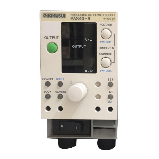
PAS 40-9
PAS 60-6
700W Type
PAS 10-70
PAS 20-36
PAS 40-18
PAS 60-12
1000W Type
PAS 10-105
PAS 20-54
PAS 40-27
PAS 60-18
PAS 80 -4.5
PAS 160-2
PAS 320-1
PAS 500-0.6
PAS 80 -9
PAS 160-4
PAS 320-2
PAS 500-1.2
PAS 80 -13.5
PAS 160-6
PAS 320-3
PAS 500-1.8
Part No. IA005084
Jan. 2017
Advertisement
Table of Contents

Subscribe to Our Youtube Channel
Related Manuals for Kikusui PAS 10-35


Summary of Contents for Kikusui PAS 10-35
- Page 1 Part No. IA005084 Jan. 2017 USER’S MANUAL Regulated DC Power Supply PAS Series 350W Type PAS 10-35 PAS 80 -4.5 PAS 160-2 PAS 20-18 PAS 40-9 PAS 320-1 PAS 60-6 PAS 500-0.6 700W Type PAS 80 -9 PAS 10-70 PAS 20-36...
- Page 2 Regulated DC Power Supply and their provided for a fee. To replace or purchase a instructors. It is assumed that the reader has manual, please contact your Kikusui agent or knowledge about electrical aspects distributor.
-
Page 3: Safety Symbols
Safety Symbols For the safe use and safe maintenance of this product, the following symbols are used throughout this manual and on the product. Understand the meanings of the symbols and observe the instructions they indicate (the choice of symbols used depends on the products). -
Page 4: Safety Precautions
Safety Precautions The following safety precautions must be observed to avoid fire hazard, electrical shock, accidents, and other failures. Keep them in mind and make sure that all of them are observed properly. Using the product in a manner that is not specified in this manual may impair the protection functions provided by the product. - Page 5 Cover • There are parts inside the product which may cause physical hazards. Do not remove the external cover. Installation • When installing products be sure to observe "1.2 Precautions for installation" described in this manual. • To avoid electrical shock, connect the protective ground terminal to electrical ground (safety ground).
- Page 6 • To maintain performance and safe operation of the product, recommended that periodic maintenance, checking, cleaning, and calibration be performed. Service • Internal service is to be done by Kikusui service engineers. If the product must be adjusted or repaired, contact Kikusui agent/distributor. IV Safety Precautions PAS SERIES...
-
Page 7: Table Of Contents
Contents Safety Symbols - - - - - - - - - - - - - - - - - - - - - - - - - - - - - - - - - - - - - - - - - - -I Safety Precautions - - - - - - - - - - - - - - - - - - - - - - - - - - - - - - - - - - - - - - - - II Preface About this manual - - - - - - - - - - - - - - - - - - - - - - - - - - - - - - - P-1... - Page 8 Chapter4 Remote Control Analog Remote Control - - - - - - - - - - - - - - - - - - - - - - - - - - - - - - - -4-1 4.1.1 About the J1 Connector - - - - - - - - - - - - - - - - - - - - - - - - - - - -4-2 4.1.2 Controlling the Output Voltage Using External Voltage - - - - - -4-5 4.1.3...
- Page 9 7.3.2 Environment - - - - - - - - - - - - - - - - - - - - - - - - - - - - - - - - - - - 7-9 7.3.3 Calibration Mode - - - - - - - - - - - - - - - - - - - - - - - - - - - - - - - 7-10 7.3.4 Calibration Procedure - - - - - - - - - - - - - - - - - - - - - - - - - - - - 7-11 Malfunctions and Causes- - - - - - - - - - - - - - - - - - - - - - - - - - - - - - 7-17...
- Page 10 This page has been intentionally left blank. VIII PAS SERIES...
-
Page 11: Preface
Preface About this manual The PAS series is classified into three types depending on the output capacity. This manual describes the following models. 350W type PAS10-35, PAS20-18, PAS40-9, PAS60-6, PAS80-4.5 REGULATED DC POWER SUPPLY PAS10 10V 35A VOLTAGE PAS160-2, PAS320-1, PAS500-0.6 OUTPUT PWR DSPL OUTPUT... -
Page 12: Outline Of The Pas Series
Equipped with a digital remote control function through TP-BUS (Twist Pair-BUS) communication. (Total length of TP-BUS is 200 m.) By combining with Kikusui's PIA4800 Series Power Supply Control- ler, systemization for applications such as an automatic tester is possi- ble. -
Page 13: Options
Options Below are options available for the PAS series. For details on the options, contact your Kikusui agent or distributor. Rack adapter KRA3 Inch rack EIA standard KRA150 Milli rack JIS standard Unit: mm (inch) Fig.P-1 Rack adapter For information on rack adapter mounting, see the KRA3 or KRA150 operation manual. - Page 14 Analog Remote Control Connector Kit (OP01-PAS) A kit for connecting to the J1 connector on the rear panel. Component Quantity Socket 1 pc. Pins 10 pcs. Protection cover 1 set Chassis connection wire 1 pc. Fig.P-2 Analog remote control connector kit P-4 Preface PAS SERIES...
-
Page 15: Chapter1 Setup
Chapter. 1 Setup This chapter describes the necessary procedure from unpacking to preparation before use. Checking at unpacking When you receive the product, check that all accessories are included and that the accessories have not been damaged during transportation. If any of the accessories are damaged or missing, contact your Kiku- sui agent /distributor. - Page 16 Plug:NEMA5-15 Pulg: CEE7/7 Pulg: GB1002 Rating:125 Vac/10 A Rating: 250 Vac/10 A Rating: 250 Vac/10 A [85-AA-0003] [85-10-1070] [85-10-0790] The power cord that is provided varies depending on the destination for the product at the factory-shipment. Power cord for the 350W/700W type (approx. 2.5 m) Accompanying nuts: [M8-500-003] 2 pcs.
-
Page 17: Precautions For Installation
3 m or less in length. If obtaining a power cord is difficult, contact your Kikusui agent or distributor. PAS SERIES Setup 1-3... - Page 18 • Do not use the AC power cord provided with the product as a AC power cord for other instruments. • The power cord with a plug can be used to disconnect the PAS series from the AC power line in an emergency. Connect the plug to an easily accessible power outlet so that the plug can be removed from the outlet at any time.
- Page 19 1000W type The AC power cord that is included with the 1000W type can be used on either a 100-VAC or 200-VAC system. WARNING Risk of electric shock. • Before you connect the power cord, turn off the switchboard breaker (a switch that cuts off the power supply from the switchboard).
- Page 20 Example circuit breaker label Example: PAS10-105 For PAS10-105 For PAS10-105 exclusive use exclusive use Switchboard (black or brown) PAS10-105 (white of blue) Supplied power cord (green or green/yellow) Fig.1-3 Connecting to the switchboard ( Example: PAS10-105 Connection procedure 1. Check that the supply voltage is within the line voltage range of the power supply.
-
Page 21: Chapter2 Before Using The Unit
Chapter. 2 Before Using the Unit Before using the unit, users are requested to thoroughly understand the following matters. Inrush Current An inrush current flows when the POWER switch is turned on. If you are planning to use several sets of the unit in a system and turn on their POWER switches simultaneously, check that the AC power source or the switchboard is of sufficient capacity. -
Page 22: When The Load Generates A Reverse Current To The Power Supply2-2
Preset constant current value Preset constant current value Meter indication value (mean value) Meter indication value (mean value) Fig.2-1 Load current with peaks Fig.2-2 Pulse-shaped load cur- rent 2.2.2 When the Load Generates a Reverse Current to the Power Supply The unit cannot absorb a reverse current from a regenerative load such as an inverter, converter, or transformer that supplies current to a power supply. -
Page 23: When The Load Has Accumulated Energy Such As Batteries
2.2.3 When the Load Has Accumulated Energy Such as Batteries Connecting a load with accumulated energy, such as a battery, to the unit may cause current to flow from the load to the internal circuit of the unit. This current may damage the unit or reduce the life of the load. -
Page 24: Cv Power Supply And Cc Power Supply
CV Power Supply and CC Power Supply This unit is capable of both constant voltage and constant current operation. This section describes these operations. An ideal constant voltage power supply has zero output impedance at all frequencies and maintains a constant voltage against all types of load current variations. - Page 25 output current increases as the output voltage increases. When the output voltage reaches 50 V (that is, the output current has reached 5 A), the output voltage no longer increases even if you attempt to raise it. This is because the output current is limited to 5 A specified initially, causing the power supply to switch to the constant current (CC) operation mode.
- Page 26 output voltage further, the unit needs to be replaced by a model hav- ing larger current capacity. Particularly for loads into which a tran- sient peak current flows, the current must be set such that its peak does not reach (or exceed) the current limit. If the unit enters constant current operation mode even when the current is set to the rated out- put current, the current capacity needs to be raised.
-
Page 27: Alarm
Alarm The unit is equipped with the following protection function. When the protection function is activated, "ALM" on the front panel display lights, and the OUTPUT is turned off or the POWER switch is shut down. However, the only action available when OHP is activated is turning off the OUTPUT. - Page 28 • OCP (overcurrent protection) The overcurrent protection function protects a load from unexpect- edly high current. The function is activated when the current exceeds a preset current (OCP trip point). Selectable range: 10 % to 110 % of the rated output current. If the OCP function is activated when CONFIG is set to OUTPUT OFF, the voltage display shows "OCP."...
- Page 29 • SHUT (Shutdown) The OUTPUT or the POWER switch can be turned OFF by applying a shutdown signal to the J1 connector on the rear panel. If the shut- down signal is applied when CONFIG is set to OUTPUT OFF, the voltage display shows "SHUT."...
-
Page 30: Grounding The Output Terminal
Grounding the Output Terminal • For safety reasons, even if the output terminal is WARNING grounded, make sure the insulation capacity of the output terminal (including the sensing terminal) is greater than the isolation voltage of the unit. If you cannot obtain a cable with sufficient rated volt- age, secure adequate withstand voltage such as by passing the cable through an insulation tube with a withstand voltage greater than the isolation voltage of... - Page 31 PAS SERIES – When remote sensing is not used: Connect to - (neg.) output terminal When remote sensing is used: – Connect to -S terminal of sensing Vext Approx. the same potential as the - (neg.) output terminal Rext Insulated Since the output terminal is floating, the section indicated 23 Approx.
- Page 32 Next, let's consider the case when the output terminal is grounded. Fig.2-11 shows the case when the + (pos.) output terminal is con- nected to the chassis terminal. In this case, the + (pos.) output termi- nal is at ground potential. Therefore, the cable and load that are connected to the output terminal (including the sensing terminal) only require an insulation capacity that is greater than the maximum out- put voltage of the unit with respect to the chassis.
-
Page 33: Chapter3 Basic Operation
Chapter. 3 Basic Operation This chapter describes how to turn on the power and the basic opera- tions that you can carry out from the front panel. Turning on the Power CAUTION • Allow at least 10 seconds between power cycles. Repeated on/off of the POWER switch at short inter- vals can cause malfunction of the inrush current limit- ing circuit and shorten the service life of the input... -
Page 34: Basic Operation
The display that appears when the POWER switch is turned on for the first time corresponds to factory default settings. The unit stores the panel settings (excluding OUTPUT ON/OFF con- dition) immediately before the POWER switch is turned off. The pre- vious panel settings are used the next time the POWER switch is turned on. -
Page 35: Setting The Output
3.2.1 Setting the Output Here, we will look at an example in which the output is set to 35 V and 7.5 A using the PAS40-9. Setting the output of the PAS40-9 to 35 V and 7.5 A 1. Check that the LOCK switch is turned off. You cannot set the output if this switch is illuminated. -
Page 36: Setting The Ovp (Overvoltage Protection) Trip Point
3.2.2 Setting the OVP (Overvoltage Protection) Trip Point The OVP function protects a load from unexpectedly high voltage. When OVP is activated, "ALM" on the display lights, and the OUT- PUT is turned off or the POWER switch is tripped. (Selectable range: 10 % to 110 % of the rated output voltage) For details on setting whether to turn off the OUTPUT or trip the POWER switch when OVP is activated, see "POWER switch trip... - Page 37 4. Press the OVP switch. The voltage display shows the preset value, and the current dis- play shows "OVP." 5. Press the VOLTAGE switch to select Coarse or Fine (preset digit). You can also switch between Coarse and Fine by pressing the dial. (The digit that is displayed brightly is the digit that you are set- ting.
-
Page 38: Setting The Ocp (Overcurrent Protection) Trip Point
3.2.3 Setting the OCP (Overcurrent Protection) Trip Point The OCP function protects a load from unexpectedly high current. When OCP is activated, "ALM" on the display lights, and the OUT- PUT is turned off or the POWER switch is tripped. (Selectable range: 10 % to 110 % of the rated output current) For details on setting whether to turn off the OUTPUT or trip the POWER switch when OCP is activated, see "POWER switch trip... -
Page 39: Unit Configuration (Config)
The following conditions activate the OCP function. • When the preset current is higher than the OCP trip point volt- age. • When the load is abnormal. • When the unit is abnormal. If you turn on the POWER switch without correcting the cause, OCP is activated again. - Page 40 Table 3-1 CONFIG settings Voltmeter DIGIT A DIGIT B DIGIT C DIGIT D Preset CV control CC control Remote PWR ON value sensing OUTPUT Panel control Panel control OFF at startup External voltage External voltage ON at startup control control External resistance External resistance control...
- Page 41 PWR ON OUTPUT (DEGIT D) Set "0" to start up the unit with the OUTPUT turned off when the POWER switch is turned on, "1" to start up the unit with the OUTPUT turned on. Master-slave series/parallel function (DEGIT E) Set the master and slave units when using series or master-slave parallel function.
- Page 42 "0" (enable), the POWER switch may turn OFF every time you turn ON the POWER switch after the initial OVP activa- tion. This is because OVP is activated every time the power is turned on. In such case, redo the CONFIG settings. Setup procedure 1.
-
Page 43: Using The Unit As A Constant Voltage Power Supply
3.2.5 Using the Unit as a Constant Voltage Power Supply This section describes the procedure for using the unit as a constant voltage power supply. 1. Check that the POWER switch is turned OFF. 2. Connect the load to the output terminal. For details on connecting the load, see "3.3 Connecting the Load". -
Page 44: Using The Unit As A Constant Current Power Supply
3.2.6 Using the Unit as a Constant Current Power Supply This section describes the procedure for using the unit as a constant current power supply. 1. Check that the POWER switch is turned OFF. 2. Connect the load to the output terminal. For details on connecting the load, see "3.3 Connecting the Load". -
Page 45: Connecting The Load
+ (pos.) and - (neg.) output lines side by side or bundling them together is more effective against unwanted noise. The Kikusui-recommended currents shown in table 3-2 are allowable current values that have been reduced in consideration of the potential bundling of load cables. - Page 46 Table 3-2 Nominal cross-sectional area of cables and allowable currents Nominal cross- (Reference Allowable cur- Current recom- sectional area cross-sectional mended by rent [mm] area) [mm] Kikusui [A] (Ta = 30°C) (0.28) (3.31) (5.26) (8.37) (13.3) (21.15) (33.62) (42.41) (53.49) (67.43) (85.01)
-
Page 47: Connecting To The Output Terminals
3.3.2 Connecting to the Output Terminals • Possible electric shock. Be sure to turn the POWER WARNING switch off before touching the output terminal on the rear panel. Be sure to attach the OUTPUT terminal cover after wiring the load. The chassis connection wire is not included. - Page 48 4. Connect the load wire to the output terminal on the rear panel. If you are using M8 screws, pay attention to the direction of the screws. Connection using M4 screws Connection using M8 screws M4 screw Crimping M8 crew terminal Crimp terminal Spring...
- Page 49 Attaching the OUTPUT terminal cover There are two types of OUTPUT terminal covers: bottom cover and top cover. 1. Insert the hook of the bottom cover into the hole located above and to the left of the output terminal. The bottom cover is the one without screws. 2.
-
Page 50: Switching The Power Display
Switching the Power Display The PAS series power supply allow you to vary the output voltage or output current while checking the output power. When varying the output voltage while checking the power If you press the SHIFT+CURRENT switch (press the CURRENT switch while pressing the SHIFT switch) when the OUTPUT is on, the current display shows the output power. -
Page 51: Lock Function
LOCK Function A LOCK switch is provided as a function to prevent inadvertently changing the settings. When the panel lock is enabled (LOCK switch lights up), the switches on the front panel (excluding the OUTPUT switch) and the dial do not function. Panel lock procedure 1. - Page 52 1. Press the POWER switch while pressing the CONFIG switch to enter the CONFIG setting mode. Turn on remote sensing through CONFIG setting. For details on CONFIG settings, see "3.2.4 Unit Configuration (CONFIG)". 2. Turn off the POWER switch. 3. As shown in Fig.3-6, connect the sensing wires between the sensing terminals and the load cable by using the screws provided.
- Page 53 CAUTION • Use a capacitor (C) whose withstand voltage is greater than or equal to 120 % of the unit's rated volt- age. NOTE • If the wiring to a load is long, the phase shift caused by the inductance and capacitance of the wiring becomes non-negli- gible, thereby causing oscillation.
- Page 54 This page has been intentionally left blank. 3-22 Basic Operation PAS SERIES...
-
Page 55: Chapter4 Remote Control
Guide” in the CD-ROM that came with the PIA4800 series. If you are using the PIA3200 Power Supply Controller, contact your Kikusui agent/distributor. Analog Remote Control The J1 connector on the rear panel can be used to control the unit in the following manner. -
Page 56: About The J1 Connector
MIL connector) are not provided. table 4-1 shows the tools an parts that are needed. For information on how to obtain the tools and parts, contact your Kikusui agent or distributor. An optional OP01-PAS Analog Remote Control Connector Kit is available for making the connection. - Page 57 Table 4-2 J1 connector arrangement Pin No. Signal Name Description Connected to the negative electrode (-S) of the sensing input when remote sensing is used; connected to - (neg.) output when remote A COM sensing is not used. Connected to the negative electrode (-S) of the sensing input when remote sensing is used;...
- Page 58 Pin No. Description Signal Name Turns ON during CV operation (open collector output by a photo- CV STATUS coupler) Turns ON during CC operation. (open collector output by a photo- CC STATUS coupler) Turns on when OVP, OCP, or OHP is activated or when a shutdown signal is input.,(open collector output by a photocoupler, held for ALM STATUS approx.
-
Page 59: Controlling The Output Voltage Using External Voltage
4.1.2 Controlling the Output Voltage Using External Voltage This method is used to control the output voltage using an external voltage (Vext) in the range 0 V to approx. 10 V. To control the output voltage using external voltage, you must set CV control of CONFIG settings to "1."... - Page 60 CAUTION • Make sure the polarity of Vext is correct. Otherwise, damage to the unit may result. • Do not apply voltage or reverse voltage exceeding 10.5 V across the external voltage control pins. Oth- erwise, damage to the unit may result. NOTE •...
- Page 61 Connecting the Shield to the Vext Side CAUTION • If you are connecting the shield to the Vext side when using external voltage control, do not connect the shield to the - (neg.) output terminal of the unit. When using shielded wires, some external voltage sources may require that the shield be connected to the external voltage source (Vext).
-
Page 62: Controlling The Output Voltage Using External Resistance
4.1.3 Controlling the Output Voltage Using External Resistance This method is used to control the output voltage using an external resistance (Rext) in the range 0 kΩ to approx. 10 kΩ. • The insulation of the external resistor (Rext) and the WARNING cable connecting it should be greater than the isola- tion voltage of the unit. - Page 63 For a portion of the 10 V, 20 V, 40 V, 60 V, and 80 V models, the products may be manufactured under the following specifications. See also Chapter8 "Specifications". 10 kΩ → MAX OUT CV mode The output voltage (Eo) varies in the range of 0 to rated output voltage by setting the external resistance (Rext) in the range of approx.
- Page 64 ■ External resistor (Rext) connection Pins 1 and 6 of the J1 connector are used. 2-core shielded or twisted-pair wire Rext Fig.4-3 Connection of the output voltage control using external resistance 4-10 Remote Control PAS SERIES...
-
Page 65: Controlling The Output Current Using External Voltage
4.1.4 Controlling the output current using external voltage This method is used to control the output current using an external voltage (Vext) in the range 0 V to approx. 10 V. To control the output current using external voltage, you must set CC control of CONFIG settings to "1."... - Page 66 • If Vext comes loose, erroneous operation may result due to external noise. Securely connect the wires to the J1 connector. • Do not apply voltage or reverse voltage exceeding 10.5 V across the external voltage control pins. Oth- erwise, damage to the unit may result. NOTE •...
- Page 67 Connecting the Shield to the Vext Side CAUTION • If you are connecting the shield to the Vext side when using external voltage control, do not connect the shield to the - (neg.) output terminal of the unit. When using shielded wires, some external voltage sources may require that the shield be connected to the external voltage source (Vext).
-
Page 68: Controlling The Output Current Using External Resistance
4.1.5 Controlling the Output Current Using External Resistance This method is used to control the output current using an external resistance (Rext) in the range 0 kΩ to approx. 10 kΩ. Press the SET switch to check the preset current. •... - Page 69 For a portion of the 10 V, 20 V, 40 V, 60 V, and 80 V models, the products may be manufactured under the following specifications. See also Chapter8 "Specifications". 10 kΩ → MAX OUT CC mode The output current (Io) varies in the range of 0 to rated output current by setting the external resistance (Rext) in the range of approx.
- Page 70 ■ External resistor (Rext) connection Pins 1 and 7 of the J1 connector are used. 2-core shielded or twisted-pair wire Rext Fig.4-6 Connection of the output current control using external resistance 4-16 Remote Control PAS SERIES...
-
Page 71: Controlling The Output On/Off Using External Contact
4.1.6 Controlling the Output ON/OFF Using External Contact This method is used to control the output on/off status using external contacts. You can select the following two types of modes through CONFIG settings. For details on CONFIG settings, see "3.2.4 Unit Configura- tion (CONFIG)". - Page 72 NOTE • If multiple units are used under floating conditions and a sin- gle external contact is used to turn on/off the output, ground the negative outputside of each power supply unit. Or, use relays or similar devices for the external contact signal to iso- late the signal flowing through each unit.
-
Page 73: Controlling The Output Shutdown Using External Contact
4.1.7 Controlling the Output Shutdown Using Exter- nal Contact This method is used to control the output shutdown using external contacts. You can select the following two types of modes through CONFIG settings. For details on CONFIG settings, see "3.2.4 Unit Configura- tion (CONFIG)". - Page 74 • The insulation of the external contact (S) and the WARNING cable connecting it should be greater than the isola- tion voltage of the unit. For details on the isolation voltage of each model, see Chapter8 "Specifica- tions". • When using shielded wires for connection, protect the uncovered section of the shielded wire by using insulation tubes with a withstand voltage greater than the isolation voltage of the unit.
-
Page 75: Remote Monitoring
Remote Monitoring 4.2.1 External Monitoring of the Output Voltage and Output Current The J1 connector consists of monitor outputs for output voltage and output current. Table 4-3 Monitor output of output voltage and output current Pin No. Signal Name Description A COM Common for remote control input and output monitor Monitor output of output voltage... -
Page 76: External Monitoring Of The Operation Mode
4.2.2 External Monitoring of the Operation Mode The J1 connector consists of status outputs that can be used to exter- nally monitor the operating condition of the unit. The status outputs consist of the following five items. The outputs are open collector outputs of photocouplers; they are insulated from the internal circuits of the unit. -
Page 77: Digital Remote Control
The list of messages and connection of power supply of Connecting & Programming guide is provided in a PDF file. Adobe Reader is required to view the PDF files. The latest version of the “Connecting & Programming Guide” can be downloaded from Web site (http://www.kikusui.co.jp/en/download/). PAS SERIES Remote Control 4-23... - Page 78 This page has been intentionally left blank. 4-24 Remote Control PAS SERIES...
-
Page 79: Chapter5 Parallel And Series Operation
Chapter. 5 Parallel and Series Operation The output voltage can be increased by connecting PAS series power supplies with the same output rating in series and operating them in master-slave series mode. Additionally, the output current can be increased by connecting PAS series power supplies with the same output rating in parallel and operating them in master-slave parallel mode. -
Page 80: Master-Slave Series Operation
Master-Slave Series Operation • Master-slave series operation is not possible on the WARNING 320 V and 500 V models. If connected in series, the output voltage will exceed the isolation voltage creat- ing a dangerous condition. 5.1.1 Functions during Master-Slave Series Opera- tion The functions of the unit during master-slave series operation are described below. - Page 81 Analog remote control Analog remote control can be performed only against the master unit. For details on the analog remote control, see "4.1 Analog Remote Control". For details, see "4.1 Analog Remote Control". Remote monitoring External monitoring of output voltage (V MON) The output voltage of each master and slave unit can be monitored.
-
Page 82: J1 Connector Connection (Series Operation)
5.1.2 J1 Connector Connection (Series Operation) For master-slave series operation, two units are connected as shown in Fig.5-2. The maximum output voltage during master-slave series operation is twice the rated output voltage of a single unit. Connecting the signal wires (series operation) The connector needed to connect the J1 connector is not provided. -
Page 83: Load Connection For Series Operation
5.1.3 Load Connection for Series Operation • When you are done with the connection, be sure to WARNING attach the output terminal cover to prevent the possi- bility of electric shock. • Securely connect the protective conductor terminal of the unit. CAUTION •... -
Page 84: Master-Slave Series Operation Setup
5.1.4 Master-Slave Series Operation Setup To perform master-slave series operation, the master and slave units as well as various protection functions must be set up. Setting the master and slave units Set the master and slave units through CONFIG settings. NOTE •... -
Page 85: Master-Slave Series Operation Procedure
OVP (overvoltage protection) setting OVP (overvoltage protection) is set on both master and slave units according to "3.2.2 Setting the OVP (Overvoltage Protection) Trip Point". OVP is set to 1/2 the voltage to be protected on each unit. However, set the OVP trip point of the slave unit slightly higher than that of the master unit, so that the OVP function of the master unit is activated first. -
Page 86: Master-Slave Parallel Operation
Master-Slave Parallel Operation 5.2.1 Functions during Master-Slave Parallel Opera- tion The functions of the unit during master-slave parallel operation are described below. Voltage display and current display As shown in Fig.5-5, the voltage is displayed only on the master unit, and the current is displayed on each unit. - Page 87 Remote monitoring External monitoring of output voltage (V MON) The output voltage can be monitored only on the master unit. External monitoring of output current (I MON) The output current of each master and slave unit can be monitored. For the total output current, sum the monitor values of the master and slave units.
-
Page 88: J1 Connector Connection (Parallel Operation)
5.2.2 J1 Connector Connection (Parallel Operation) For master-slave parallel operation, two units are connected as shown in Fig.5-6. The maximum output current during master-slave parallel operation is equal to the number of units connected in parallel multiplied by the rated output current of a single unit. Connecting the signal wires (parallel operation) The connector needed to connect the J1 connector is not provided. -
Page 89: Load Connection For Parallel Operation
Master unit Slave unit1 Slave unit2 12 10 12 10 Slave unit Master unit PRL OUT 12 PRL IN – – PRL OUT 14 PRL IN [PRL COMP OUT] [PRL COMP IN] STATUS COM 17 STATUS COM ALM STATUS 10 SHUT DOWN Slave unit OUTON STATUS 21 3 OUT ON/OFF CON... - Page 90 Connection procedure 1. Check that the POWER switch is off on all power supply units to be connected in parallel. 2. Remove the output terminal cover. 3. Connect the cables as shown in Fig.5-7. Refer to "3.3 Connecting the Load" and select a load cable with sufficient current capacity.
-
Page 91: Master-Slave Parallel Operation Setup
5.2.4 Master-Slave Parallel Operation Setup To perform master-slave parallel operation, the master and slave units as well as various protection functions must be set up. Setting the master and slave units Set up the master and slave units through CONFIG settings. NOTE •... -
Page 92: Master-Slave Parallel Operation Procedure
OVP (overvoltage protection) setting OVP (overvoltage protection) is set on both master and slave units according to "3.2.2 Setting the OVP (Overvoltage Protection) Trip Point". However, set the OVP trip point of the slave unit slightly higher than that of the master unit, so that the OVP function of the master unit is activated first. -
Page 93: Chapter6 Names And Functions Of Controls
Chapter. 6 Names and Functions of Controls This chapter describes the names and functions of switches, displays, connectors, and other parts of the front panel and rear panel. Front Panel DISPLAY section 8 VOLTAGE /PWR DSPL REGULATED DC POWER SUPPLY PAS10 10V 35A 6 OUTPUT... - Page 94 [3] LOCK Switch used to disable all operations except turning on/off of the OUTPUT. The switch lights while the unit is locked. To release, press the switch again. For details, see "3.5 LOCK Function". [4] CONFIG If turn on the POWER switch while pressing the CONFIG switch, you can set the various setting of operation of the unit (CONFIG set- ting mode).
- Page 95 1) Voltmeter Indicates the preset output voltage during setup mode when the SET switch is illuminated. Indicates the output voltage when the SET switch is not illuminated. Indicates the OVP trip point when the OVP switch is illuminated. Indicates the power when the unit is switched to power display. 2) Voltmeter unit Indicates the unit V of the displayed voltage value.
- Page 96 [8] VOLTAGE/ PWR DSPL Selects the digit when setting the voltage. The digit changes for each click. Pressing the VOLTAGE switch while pressing the SHIFT switch dis- plays the output power on the voltage display. See "3.4 Switching the Power Display". [9] CURRENT/ PWR DSPL Selects the digit when setting the current.
-
Page 97: Rear Panel
Rear Panel 16 TP-BUS 18 Sensing terminal 15 J1 14 DC OUTPUT 19 Exhaust port 13 AC INPUT 13 AC INPUT 1000W Type Fig.6-3 Rear panel [13] AC INPUT AC power cord connector (350W and 700W types) or terminal board (1000W type) used to supply power to the unit. - Page 98 For details, see "4.1 Analog Remote Con- trol" and "4.2 Remote Monitoring". [16] TP-BUS Connector used to connect to a Kikusui's PIA4800 Series Power Sup- ply Controller using a twisted-pair cable when digital remotely con- trolling the unit.
-
Page 99: Chapter7 Maintenance
Chapter. 7 Maintenance This chapter describes maintenance and inspection of the unit. Con- duct periodic maintenance and inspection to maintain the initial per- formance as long as possible. Cleaning WARNING • When cleaning the unit, be sure to turn off the POWER switch and remove the AC power cord plug or turn off the switchboard. -
Page 100: Cleaning The Dust Filter
7.1.2 Cleaning the Dust Filter A dust filter is installed on the inside of the louver on the front panel. Periodically clean the filter for prevent clogging. CAUTION • Clogged filters hinder the cooling of the inside of the unit and can cause malfunction and shortening of the service life. - Page 101 3. Attach the dust filter to the louver. Be sure the direction of the louver and dust filter is correct. Fig.7-2 Attaching the dust filter 4. Bend the filter and hold it with your fingers. Then, attach the louver to the panel. Fig.7-3 Attaching the Louver 5.
- Page 102 ■ 700W and 1000W types Filter below the operation panel 1. As shown in Fig.7-5, pull the bottom section of the louver toward you and remove the louver from the panel. Fig.7-5 Removing the louver 2. Remove the dust filter from the inside of the louver and clean it.
- Page 103 4. Bend the filter and hold it with your fingers. Then, attach the lou- ver to the panel. At this point, align the hook on the right side of the louver to the inside the panel as shown in Fig.7-7. Fig.7-7 Attaching the Louver 5.
- Page 104 Filter on the side of the operation panel 1. As shown in Fig.7-10, pull down the top section of the louver while pulling the bottom step toward you. Fig.7-10Removing the louver 2. Remove the dust filter from the inside of the louver and clean it.
- Page 105 3. Attach the dust filter to the louver. Attach it so that the dust filter fits inside the hooks of the louver. Dust filter Hook Louver Fig.7-11Attaching the dust filter 4. Align and set the hooks of the louver to the grooves. While pressing the fourth step from the bottom, slide the louver upward to attach it to the panel.
-
Page 106: Inspection
For calibration, contact your Kikusui agent/distributor. If you wish to calibrate the unit, follow the procedure below. The calibration proce- dure includes all calibration items of the unit. -
Page 107: Environment
Table 7-1 Recommended shunt resistor Shunt Resistor Type Rating Accuracy 350W Type PAS10-35 50 A / 50 mV (1 mΩ) PAS20-18 20 A / 50 mV (2.5 mΩ) PAS40-9 10 A / 50 mV (5 mΩ) PAS60-6 10 A / 50 mV (5 mΩ) PAS80-4.5 5 A / 50 mV (1 mΩ) PAS160-2... -
Page 108: Calibration Mode
7.3.3 Calibration Mode To calibrate the unit, the unit must be put into calibration mode. Turning on the POWER switch while pressing the SET switch causes the unit to enter the calibration mode after displaying the version number. The display is shown below. To exit the calibration mode, turn off the POWER switch. -
Page 109: Calibration Procedure
■ Calibration status indication The calibration status indication switches according to the calibration operation as follows: 0: Calibration start 1: Offset adjustment procedure complete 2: Full scale adjustment procedure complete 3: Offset and full scale procedure complete 7.3.4 Calibration Procedure The following eight types of calibrated items are available. - Page 110 Voltage calibration procedure ■ Connecting the equipment 1. Turn off the POWER switch. 2. Connect a DVM to the output terminal. Shown in Fig.7-15. Fig.7-15Connection for voltage system calibration ■ Warming up 3. Turn on the POWER switch while pressing the SET switch. 4.
- Page 111 13.Turn off the OUTPUT. The voltage display shows "FS 3." 14.Press the SET switch to store the calibration value. The voltage display returns to "FS 0." You are done calibrating the output voltage. If you wish to exit from the output voltage calibration here, turn off the POWER switch.
- Page 112 NOTE • If you make a mistake in the calibration procedure or connec- tion and the POWER switch immediately turns OFF when the OUTPUT is turned on by performing steps 8 through 13, the OVP calibration value may be off by a great extent. In such case, repeat steps 3 through 8 or 9 through 13 until the POWER switch turns off after 30 s to 60 s.
- Page 113 ■ Output current offset and full scale 6. Press the CURRENT switch to display "OF 0" on the cur- rent display. 7. Turn on the OUTPUT. Approximately 10 % of the rated output current is output. 8. Turn the dial so that the DVM reading is equal to 10 % of the rated output current.
- Page 114 ■ Warming up 3. Turn on the POWER switch while pressing the SET switch. 4. Check that the voltage display shows "CAL." If it is not, press the CURRENT switch. 5. Warm up the equipment including the shunt resistor and DVM for sufficient time.
-
Page 115: Malfunctions And Causes
If you find an item that corresponds to your case, follow the remedy for the item. If the remedy does not solve the problem or if your case does not match any of the items, contact your Kikusui agent/distributor. Symptom1: The panel displays nothing. - Page 116 Check Item Cause and Remedy □ A special load is con- • The output overvoltage protection function may be nected. activated. See "2.2 Load". □ The control cable for • The output overvoltage protection function has analog remote control is been activated.
- Page 117 Symptom4: The output is unstable. Check Item Cause and Remedy □ The operation mode • Change the setting (VOLTAGE or CURRENT) switches from CV to that is limiting the output to a value greater than CC or CC to CV. the current setting.
- Page 118 Symptom5: The output ripple is large. Check Item Cause and Remedy □ The input voltage is • Supply a voltage that is within the input voltage outside the range. range. □ A source of strong mag- • Being subjected to electromagnetic induction. netic or electrical field Take measures such as moving the unit away from is nearby.
-
Page 119: Chapter8 Specifications
Chapter. 8 Specifications This chapter contains the specifications of the unit. Unless otherwise specified, the specifications are based on the fol- lowing conditions. • The load is a pure resistance. • After a warm-up of 30 minutes with current flowing through the load. -
Page 120: Common Specifications
Common Specifications Common Specifications Notes Input Specifications 100 VAC/ 200 VAC Input voltage 100 VAC to 240 VAC systems (85 VAC to 250 VAC) Operable without switching 50 Hz to 60 Hz Frequency — (47 Hz to 63 Hz) Number of phase Single phase —... - Page 121 Common Specifications Notes Display Function (cont.) Power display (PWR DISP) Displays the calculated output power in the voltmeter or ammeter. Red LED The W LED illuminates for the corresponding display sec- tion indicating the power. Operation OUTPUT on/off ON: ON LED illuminates/ Green LED display OFF: OFF LED illuminates...
- Page 122 Common Specifications Notes Signal output (cont.) Status signal OUTON STATUS Turns on when OUTPUT is — *1, *2 turned on. output CV STATUS Turns on during CV operation. — CC STATUS Turns on during CC operation. — Turns on when an alarm (OVP, ALM STATUS OCP, OHP, or SHUT) is acti- —...
- Page 123 Common Specifications Notes General (cont.) Environment Storage ambient 90 % RH or less. — specifications No condensation. humidity Cooling system With thermal-sensing Forced air cooling using a fan. control (FAN control) Grounding polarity Negative grounding or posi- — tive grounding possible. Isolation voltage ±...
- Page 124 Common Specifications General (cont.) Accessories Setup guide 1 pc. Quick reference Japanese: 1 pc., English: 1 pc. Safety information 1 pc. CD-ROM 1 pc 350W and SVT3 18AWG 3 P plug, Power cord 700W types with connector Cable length 2.5 m: 1 pc. 1 000W type VCT3 3.5 mm2 plug, without connector Cable length 3 m: 1 pc.
- Page 125 This is a Group 1 equipment. The PAS does not generate and/or use intentionally radio- frequency energy, in the from of electromagnetic radiation, inductive and/or capacitive coupling, for the treatment of material or inspection/analysis purpose. This is a Class I equipment. Be sure to ground the PAS's protective conductor terminal. The safety of this product is only guaranteed when the product is properly grounded.
-
Page 126: Type Specifications
350W Type Specifications 350W Type 10-35 20-18 40-9 60-6 80-4.5 Output Specifications Power Rated output power 350 W 360 W 360 W 360 W 360 W Voltage Rated output voltage 10.00 V 20.00 V 40.00 V 60.00 V 80.00 V Maximum preset voltage 105 % of rating (typ) - Page 127 — — 350W Type (cont.) 160-2 320-1 500-0.6 Output Specifications Power Rated output power 320 W 320 W 300 W — — Voltage Rated output voltage 160.0 V 320.0 V 500.0 V — — Maximum preset voltage 105 % of rating —...
- Page 128 350W Type 10-35 20-18 40-9 60-6 80-4.5 Output Specifications (cont.) Current Rated output current 35.00 A 18.00 A 9.000 A 6.000 A 4.500 A Maximum preset current 105 % of rating (typ) Accuracy of setting 0.5 % of rating + 20 mA Source effect 0.1 % of rating + 10 mA Load effect...
- Page 129 — — 350W Type (cont.) 160-2 320-1 500-0.6 Output Specifications (cont.) Current Rated output current 2.000 A 1.000 A 600.0 mA — — Maximum preset current 105 % of rating — — (typ) — — Accuracy of setting 0.5 % of rating + 5 mA —...
- Page 130 350W Type 10-35 20-18 40-9 60-6 80-4.5 General Approx. 3 kg (6.61 lbs) Weight Dimensions See outline drawing 350W Type (cont.) — — 160-2 320-1 500-0.6 General Approx. 3 kg (6.61 lbs) — — Weight Dimensions See outline drawing — —...
- Page 131 This page has been intentionally left blank. PAS SERIES Specifications 8-13...
-
Page 132: Type Specifications
700W Type Specifications 700W Type 10-70 20-36 40-18 60-12 80-9 Output Specifications Power Rated output power 700 W 720 W 720 W 720 W 720 W Voltage Rated output voltage 10.00 V 20.00 V 40.00 V 60.00 V 80.00 V Maximum preset voltage 105 % of rating (typ) - Page 133 — — 700W Type (cont.) 160-4 320-2 500-1.2 Output Specifications Power Rated output power 640 W 640 W 600 W — — Voltage Rated output voltage 160.0 V 320.0 V 500.0 V — — Maximum preset voltage 105 % of rating —...
- Page 134 700W Type 10-70 20-36 40-18 60-12 80-9 Output Specifications (cont.) Current Rated output current 70.00 A 36.00 A 18.00 A 12.00 A 9.000 A Maximum preset current 105 % of rating (typ) Accuracy of setting 0.5 % of rating + 20 mA Source effect 0.1 % of rating + 10 mA Load effect...
- Page 135 — — 700W Type (cont.) 160-4 320-2 500-1.2 Output Specifications (cont.) Current Rated output current 4.000 A 2.000 A 1 200.0 mA — — Maximum preset current 105 % of rating — — (typ) — — Accuracy of setting 0.5 % of rating + 5 mA —...
- Page 136 700W Type 10-70 20-36 40-18 60-12 80-9 General Approx. 5 kg (11.02 lbs) Weight Dimensions See outline drawing — — 700W Type (cont.) 160-4 320-2 500-1.2 General Approx. 5 kg (11.02 lbs) — — Weight Dimensions See outline drawing — —...
- Page 137 This page has been intentionally left blank. PAS SERIES Specifications 8-19...
-
Page 138: Type Specifications
1 000W Type Specifications 1 000W Type 10-105 20-54 40-27 60-18 80-13.5 Output Specifications Power Rated output power 1 050 W 1 080 W 1 080 W 1 080 W 1 080 W Voltage Rated output voltage 10.00 V 20.00 V 40.00 V 60.00 V 80.00 V... - Page 139 — — 1 000W Type (cont.) 160-6 320-3 500-1.8 Output Specifications Power Rated output power 960 W 960 W 900 W — — Voltage Rated output voltage 160.0 V 320.0 V 500.0 V — — Maximum preset voltage 105 % of rating —...
- Page 140 1 000W Type 10-105 20-54 40-27 60-18 80-13.5 Output Specifications (cont.) Rated output current 105.0 A 54.00 A 27.00 A 18.00 A 13.50 A Maximum preset current 105 % of rating (typ) Accuracy of setting 0.5 % of rating + 20 mA Current Source effect 0.1 % of rating + 15 mA...
- Page 141 — — 1 000W Type (cont.) 160-6 320-3 500-1.8 Output Specifications (cont.) Current Rated output current 6.000 A 3.000 A 1 800.0 mA — — Maximum preset current 105 % of rating — — (typ) — — Accuracy of setting 0.5 % of rating + 5 mA —...
- Page 142 1 000W Type 10-105 20-54 40-27 60-18 80-13.5 General Approx. 7 kg (15.43 lbs) Weight Dimensions See outline drawing — — 1 000W Type (cont.) 160-6 320-3 500-1.8 General Approx. 7 kg (15.43 lbs) — — Weight Dimensions See outline drawing —...
-
Page 143: Index
Index External Resistance - - - - - 4-8 4-14 External Voltage - - - - - - - 4-5 4-11 AC INPUT - - - - - - - - - - - - - - - 6-5 AC power cord - - - - - - - - - - - - 1-3 Accessories - - - - - - - - - - - - - - 1-2 ADDRESS - - - - - - - - - - - - - - - 6-1 Factory default setting - - - - - - - 3-2... - Page 144 SHUT (Shutdown) - - - - - - - - - -2-9 signal terminal OCP (Overcurrent Protection) Maximum rating - - - - - - - - 4-22 - - - - - - - - - - - - - - - - - - 2-8 Slave unit - - - - - - - - - - - - - - - -5-1 calibration - - - - - - - - - - - - 7-15 OHP (Overheat Protection) - - - - 2-8...
- Page 146 KIKUSUI ELECTRONICS CORP. 1-1-3 Higashiyamata, Tsuzuki-ku, Yokohama, 224-0023, Japan Tel: +81-45-593-7570 Fax: +81-45-593-7571 http://www.kikusui.co.jp/en Website...
Need help?
Do you have a question about the PAS 10-35 and is the answer not in the manual?
Questions and answers