Table of Contents
Advertisement
Quick Links
User's Manual
Regulated DC Power Supply
PAT-T Series
4 kW type
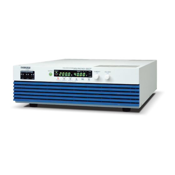
PAT20-200T
PAT40-100T
PAT60-67T
PAT160-25T
8 kW type
PAT20-400T
PAT30-266T
PAT40-200T
PAT60-133T
PAT80-100T
PAT160-50T
PART NO. IB025483
Jun. 2016
PAT250-32T
PAT350-22.8T
PAT500-16T
PAT650-12.3T
PAT850-9.4T
Description
Load and cable
Basic Operation
External Control
Parallel/Series Operation
Maintenance
Troubleshooting
General
1
2
3
4
5
Options
Appx
7
8
Appx
Advertisement
Table of Contents

Related Manuals for Kikusui PAT20-200T


Summary of Contents for Kikusui PAT20-200T
- Page 1 PART NO. IB025483 Jun. 2016 General Description Load and cable Basic Operation User’s Manual External Control Regulated DC Power Supply PAT-T Series Parallel/Series Operation 4 kW type PAT20-200T Maintenance PAT40-100T PAT60-67T Options Appx PAT160-25T Troubleshooting 8 kW type PAT20-400T PAT250-32T PAT30-266T PAT350-22.8T...
-
Page 2: Checking The Package Contents
Both unit specifications and manual contents are subject to change without notice. • The word "PC" used in this manual is a generic term for personal computers and workstations. © 2010 Kikusui Electronics Corporation • The following marks are used with the explanations in this manual. WARNING... -
Page 3: Table Of Contents
Contents Contents by Function ..................... 6 Front panel ......................8 Rear panel ......................10 Load and cable Load Considerations ....................12 Load Cable........................ 14 Basic Operation Phase input mode ....................18 Measured Value Display and Setting Display ............19 Output Operation ...................... 20 Constant Voltage (CV) and Constant Current (CC) Power Supplies ...... - Page 4 4.2.2 Load Connection (Series Operation)............. 80 4.2.3 Series Operation Setup ................. 81 4.2.4 Starting the Series Operation ................ 81 Maintenance Inspection ......................... 84 Calibration......................... 87 5.2.1 Calibration Overview ..................87 5.2.2 Calibration Procedure..................88 Appendix Options ........................96 Troubleshooting ......................99 Index ..............105 PAT-T...
- Page 5 This page is intentionally blank. PAT-T...
-
Page 6: Contents By Function
Contents by Function ➔ 1.1, "Checking the Package Contents" p. 2 • I want to check the accessories. Preparation ➔ For information about precautions concern- • The installation space is limited. How much space is ing installation, see the accompanying setup needed around the air inlet and outlet? guide or safety information. - Page 7 2.5, "Using the PAT as a CV or CC Power • How can I use the PAT as a constant voltage power Operation Supply" supply (CV)? ➔ p. 24 • How can I use the PAT as a constant voltage current supply (CC)? ➔...
-
Page 8: Front Panel
Front panel PRESET A OUTPUT ALARM LOCK Display and keys Examples of PAT20-400T PAT-T... - Page 9 Name Function +SHIFT POWER switch Power on/off lever – Raise the lever to turn the power on ( ). Lower to turn the power off ( POWER To change the phase input mode to the single-phase input, +STORE – switch press the POWER switch with pressing the STORE key.
-
Page 10: Rear Panel
Rear panel 22 23 Examples of PAT40-100T (4 kW type) 22 23 Examples of PAT20-400T (8 kW type) Name Function 22 J1 Connector for external analog control. p. 48 23 J2 Connector for parallel operation. p. 72 24 Option slot Slot for installing the optional interface board (GPIB, USB or LAN). -
Page 11: Load And Cable
Load and cable This chapter describes consideration to be given to the load and explains how to connect the load wires. -
Page 12: Load Considerations
Load Considerations Note that the output will become unstable if the following types of loads are connected. Load with peaks and pulse-shaped current The PAT indicates only mean values. Even when the indicated value is less than the preset current value, the peak values may actually exceed the preset current value. If this happens, the PAT is instantaneously put into constant-current operation mode, and the output voltage drops accordingly. - Page 13 CAUTION • Use a resistor with sufficient rated power for resistor R • If a resistor with insufficient rated power for the circuit is used, resistor R may burn out. Load with accumulated energy Connecting a load with accumulated energy, such as a battery, to the PAT may cause current to flow from the load to the internal circuit of the PAT.
-
Page 14: Load Cable
Load Cable WARNING To prevent the possibility of fire. • Use a load cable with sufficient current capacity with respect to the rated output current of the PAT. • The output terminal and its area nearby gets very high temperature, use the cable with sufficient an allowable temperature higher than 85 °C of the covering materials. - Page 15 However, installing the + (pos.) and - (neg.) output wires of the load cable side by side or bundling them together is more effective against unwanted noise. The Kikusui-recommended currents shown in Table 1-1 are allowable current values that have been reduced in consideration of the potential bundling of load cables. Use these values as a guideline when connecting load cables.
- Page 16 This page is intentionally blank. PAT-T...
-
Page 17: Basic Operation
Basic Operation This chapter describes how to turn on/ off the output and the basic operations that you can carry out from the front panel. -
Page 18: Phase Input Mode
Phase input mode The input power mode of the PAT (4kW type) can be switched to either three-phase input or the single-phase input. Before starting the operation, confirm the status of phase input mode. To verify the p. 31 status and setting of the phase input mode, refer to the ”2.7 CONFIG Settings”. The principal of difference in specifications for the phase input mode are described “Specification”... -
Page 19: Measured Value Display And Setting Display
Measured Value Display and Setting Display The panel display has two modes. One mode displays the measured values of the output voltage and output current, and the other mode displays the settings. These two modes can be distinguished by the on/off state of the SET, OVP•OCP, and CONFIG keys. -
Page 20: Output Operation
Output Operation The OUTPUT switch is a toggle switch. When you press the OUTPUT switch and the output turns on, the OUTPUT LED illuminates. When you press the OUTPUT switch and the output turns off, the OUTPUT LED turns off. If the output is turned on, the present setting is output. - Page 21 Output on/off delay functions You can set a delay (0.1 s to 10.0 s) until the output is actually turned on or off after p. 33 you turn the OUTPUT switch on or off. This function is useful if you want to turn the output on/off by setting a time offset according to the load characteristics.
-
Page 22: Constant Voltage (Cv) And Constant Current (Cc) Power Supplies
Constant Voltage (CV) and Constant Current (CC) Power Supplies The PAT has a constant voltage power supply function that maintains the output voltage at a constant level and a constant current power supply function that maintains the output current at a constant level even when the load changes. The condition in which the PAT is operating as a constant voltage power supply is called the constant voltage (CV) mode. - Page 23 When operating in CC mode, the output current is maintained at the preset current. Output voltage V is determined by the relationship defined by the equation V = Is × . It is a voltage less than voltage limit Vs. In this mode, the actual voltage that is applied is not necessarily equal to the specified value.
-
Page 24: Using The Pat As A Cv Or Cc Power Supply
Using the PAT as a CV or CC Power Supply When using the PAT as a constant voltage power supply, the preset current is the limit that can flow through the load. When using the PAT as a constant current power supply, the preset voltage is the limit that can be applied to the load. -
Page 25: Protection Functions And Alarms
Protection Functions and Alarms The PAT is equipped with the following protection function. • Overvoltage protection (OVP) • Overcurrent protection (OCP) • Overheat protection (OHP) • Overheat protection of the bleeder circuit (BOHP) • Fan failure protection (FAN) • Incorrect sensing connection protection (SENSE) •... -
Page 26: Overvoltage Protection (Ovp) And Overcurrent Protection (Ocp)
If you cannot clear the alarm even when all of the causes of the alarm occurrence are eliminated, the PAT may have malfunctioned. If this happens, stop using the PAT and contact your Kikusui agent or distributor. The cause of the alarm occurrences are described in the protection functions. - Page 27 The OVP operates on the output terminal voltage. If you want to activate the function on the voltage across the load, set the OVP trip point by considering the voltage drop in the load cable. Press the OVP•OCP key. • The OVP OCP key LED illuminates, and the specified OVP/OCP trip point is shown on the display.
- Page 28 When the setting value of output voltage exceeds OVP trip point, the ALARM LED on the front panel display illuminates and either of the POWER switch or the output will be turned off (Depending on the CONFIG settings: CF28). When the POWER switch is turned off, the ALARM LED illuminates even the power turns off, and the overvoltage protection (OVP) power-off display will be displayed for about a few seconds (4 kW type:4 to 5 seconds, 8 kW type:10 to 15 seconds).
-
Page 29: Other Protection Functions
2.6.2 Other Protection Functions Overheat protection (OHP) Overheat protection of the bleeder circuit (BOHP) This function is activated when the internal temperature of the PAT rises abnormally, and the output turns off ( the breaker trips for 400 V input models when overheat protection (OHP) activates). - Page 30 Incorrect sensing connection protection (SENSE) This function is activated when the remote sensing wires are connected with the polarity reversed of + (pos.) and - (neg.), and the output turns off. PRESET A OUTPUT Fig.2-16 Alarm display of incorrect ALARM sensing connection protection LOCK (SENSE)
-
Page 31: Config Settings
CONFIG Settings CONFIG settings are used to set the system configuration of the PAT. You can set or display the parameters in Table 2-1 in the CONFIG settings. On the top panel of the PAT is a label that indicates a list of CONFIG parameters and settings. Table 2-1 CONFIG parameters Parameter... - Page 32 Setup and view procedure of CONFIG parameters CF01, CF02, CF50, CF52, CF53 and CF57 to CF61 are parameters only for viewing the status. You cannot set them. CF50 to CF61 appear only when the option board is installed. The display of the setting varies depending on the interface option.
-
Page 33: Config Parameter Details
CONFIG parameter details CF01 Alarm cause display Displays the cause of the alarm occurrence (while the ALARM LED is illuminated). If there are multiple causes, the sum of each cause is displayed. Display Description Not an alarm condition (ALARM LED is off) Overvoltage protection (OVP) Overcurrent protection (OCP) overheat protection (OHP) - Page 34 CF12 Preset recall setting while locked Sets whether preset memory values can be recalled even when the lock function is p. 42 enabled. Settings Description Able to recall preset memory values in the locked condition Unable to recall preset memory values in the locked condition (factory default) CF13 Communication error display setting Sets whether to display communication errors by performing a device trace.
- Page 35 CF22 External control logic setting of the output on/off Sets the logic used to control the output on/off using an external contact (J1 p. 63 connector). Cannot be set when the output is on. Select “H” when not controlling the output on/off with an external contact. Settings Description Turn the output on with a high signal (factory default)
- Page 36 CF26 Master-Slave parallel operation setting Sets the PAT condition during master-slave parallel operation. Cannot be set when p. 75 the output is on. The setting is possible even when the product is used as a slave unit. Settings Description Master unit or independent operation (factory default) Slave unit CF27 Breaker trip setting when the shutdown signal is applied Sets whether to trip the breaker (turn the POWER switch off) when an external...
- Page 37 CF31 Phase input mode setting (three-phase input mode or single-phase input mode) Sets the phase input mode. This setting is possible even when the product is used as a slave unit in Master-Slave parallel operation. PRESET A OUTPUT ALARM LOCK Fig.2-22 Three-phase input mode PRESET A OUTPUT...
- Page 38 CF41 RS232C data length setting Sets the RS232C data length. The setting is possible even when the product is used as a slave unit. Settings Description 7bIt 7 bits 8bIt 8 bits (factory default) CF42 RS232C stop bit setting Sets the RS232C stop bit. The setting is possible even when the product is used as a slave unit.
- Page 39 CF53 Product ID display Displays the product ID. Displayed only when the factory option USB interface is installed. Display Description 100E 0x100E CF54 Remote interface setting Sets the remote interface that is to be used. Displayed only when the factory option interface is installed.
- Page 40 CF56 AUTO IP address setting When the DHCP is not used or not enable to be used, set whether to fix the IP address automatically. The IP address assigned by the AUTO IP is 169.254.x.x (x is 0 to 254). Displayed only when the factory option LAN interface is installed.
-
Page 41: Preset Memory Function
Preset Memory Function The PAT has a function that stores up to three combinations of voltage setting and current setting. You can store a combination by selecting memory key A (PRESET A), B (PRESET B), or C (PRESET C). RECALL keys allow you to recall any of the three preset memory values. When the phase input mode is changed to the single-phase input mode from the three-phase input mode for 4kW type, the setting value of the output current and the overcurrent protection (OCP) is limited to 75 % of the three-phase input mode. -
Page 42: Lock Function
If the voltage or current setting is limited in the CONFIG settings (CF29 or CF30: ON) and the recalled preset memory values exceed the OVP or OCP trip point, the output setting is limited to approximately 95 % of the OVP or OCP trip point. Then, PRESET A, B, or C LED corresponding to the preset memory that was recalled illuminates for approximately 1 second and turns off. -
Page 43: 2.10 Switching From Remote To Local Mode
2.10 Switching from Remote to Local Mode When the PAT is operating under remote control, the RMT LED on the display illuminates. PRESET A OUTPUT ALARM LOCK Fig.2-25 Panel display example in remote mode To switch from the remote mode to the local mode (panel operation) from the panel, press the LOCAL key. - Page 44 If the sensing wires come loose, the output voltage across the load cannot be stabilized and may cause excessive voltage to be applied to the load. If an appropriate OVP trip point is set, the OVP trips and prevents excessive voltage output.
- Page 45 Turn the POWER switch off. Turn on the sensing switch on the rear panel. As shown in Fig.2-28, connect the sensing cable between the sensing terminal and the load terminal. To decrease output ripple voltages resulting from inductive effects, use a two-core shielded wire for the sensing wires.
-
Page 46: 2.12 Factory Default Settings
2.12 Factory Default Settings Turning ON the POWER switch while holding down the SHIFT key initializes the settings to factory default. Carry out this operation when you want to reset all settings to factory default values. The factory default settings are given in the tables below. -
Page 47: External Control
External Control This chapter describes external analog control and remote monitoring using the J1 connector. -
Page 48: Overview Of External Control
At the factory shipment, the protection socket is attached to the J1 connector. Keep this protection socket and be sure to attach when the J1 connector is not used. If the protection socket is damaged or lost, contact Kikusui distributor/agent. [84-49-0110] Fig.3-2... - Page 49 Table 3-1 Connector parts by Omron needed to connect the J1 connector Product Model Kikusui parts no. Notes Single contact connection tool XY2B-7006 Y2-070-001 Not included. Contact removal tool XY2E-0001 Y2-070-002 Not included. Pin (contact) XG5W-0031 84-49-0100 Recommended wire size AWG24 (UL-1061).
- Page 50 Table 3-2 J1 connector pin arrangement Signal Name Description STATUS COM Common for status signals from pin 3 through 7. STATUS COM Common for status signals from pin 3 through 7. PWR ON/OFF PWR ON STATUS (CF23: 0): Output a low level signal while the power is on. PWR OFF STATUS (CF23: 1): Output a low level signal when the power is off.
-
Page 51: Output Terminal Insulation
Output terminal Insulation Note the following points and insulate the output terminals. WARNING • Possible electric shock. For safety reasons, even if the output terminal is grounded, make sure the insulation capacity of the output terminal (including the sensing terminal) is greater than the isolation voltage of the PAT. -
Page 52: When The Output Terminal Is Not Grounded (Floating)
3.3.1 When the Output terminal Is Not Grounded (Floating) The output terminal of the PAT is isolated from the protective conductor terminal. By connecting the GND wire of the power cable to the ground terminal of the switchboard, the chassis of the PAT is set to ground potential as shown in Fig.3-3. Pins 10 through 26 of the J1 connector on the rear panel (for external control and output monitoring) are at approximately the same potential as the - (neg.) output terminal of the PAT. -
Page 53: When The Output Terminal Is Grounded
3.3.2 When the Output terminal Is Grounded If the positive output terminal is connected to the chassis terminal, the terminal is at ground potential as shown in Fig.3-4. The cable and load that are connected to the output terminal (including the sensing terminal) will only require an insulation capacity that is greater than the maximum output voltage of the PAT with respect to the chassis. - Page 54 When using the external voltage (Vext) Connect the wires so that the output is not shorted as shown in Fig.3-5 and Fig.3-6. CAUTION The signal wire may burn out. • The signal wire may burn out. Leave the Vext output floating. •...
-
Page 55: Controlling The Output Voltage
Controlling the Output Voltage This section explains the method used to control the output voltage using an external voltage (Vext) in the range 0 V to approx. 10 V or an external resistor (Rext) in the range 0 kΩ to approx. 10 kΩ. The output voltage will change approximately 5 ms after the value of the applied external voltage or resistance changes. - Page 56 • EXT-V (FAST) CV CONT (CF20: 4) The output voltage (Eo) varies in the range of 0 to the rated output voltage (Ertg) by setting the external voltage (Vext) in the range of 0 V to 10 V. Eo = Ertg × Vext /10 [V] Vext = 10 ×...
-
Page 57: External Resistance (Rext) Control
3.4.2 External resistance (Rext) control To control the output voltage using Rext, select the CV control source in the p. 34 CONFIG settings from the following modes. • EXT-R CV CONT 10 k MAX OUT (CF20: 2) Ω → The output voltage (Eo) varies in the range of 0 to the rated output voltage (Ertg) by setting the external resistance (Rext) in the range of 0 k to 10 k Ω... - Page 58 External resistance (Rext) connection For Rext, use a 1/2 W or larger metal film or wire-wound type resistor with good temperature coefficient and small aging effect. To minimize the influence of noise on the output, use a two-core shielded wire or a twisted-pair wire to connect the control terminals and Rext.
-
Page 59: Controlling The Output Current
Controlling the Output Current This section explains the method used to control the output current using an external voltage (Vext) in the range 0 V to approx. 10 V or an external resistor (Rext) in the range 0 k Ω to approx. - Page 60 • EXT-V (FAST) CC CONT (CF21: 4) The output current (Io) varies in the range of 0 to the rated output current (Irtg) by setting the external voltage (Vext) in the range of 0 V to 10 V. Io = Irtg × Vext / 10 [A] Vext = 10 ×...
-
Page 61: External Resistance (Rext) Control
3.5.2 External Resistance (Rext) Control To control the output current using Rext, select the CC control source in the p. 34 CONFIG settings from the following modes. • EXT-R CC CONT 10 k MAX OUT (CF21: 2) Ω → The output current (Io) varies in the range of 0 to the rated output current (Irtg) by setting the external resistance (Rext) in the range of 0 kΩ... - Page 62 External resistance (Rext) connection For Rext, use a 1/2 W or larger metal film or wire-wound type resistor with good temperature coefficient and small aging effect. To minimize the influence of noise on the output, use a two-core shielded wire or a twisted-pair wire to connect the control terminals and Rext.
-
Page 63: Controlling The Output On/Off
Controlling the Output On/Off This section explains the method used to control the on/off of the output by connecting an external contact. WARNING Possible electric shock. • The insulation of the external contact (S) and the connected cable should be greater than the isolation voltage of the PAT. For the isolation voltage of each model, see "Specifications."... - Page 64 External contact connection. Pins 13 and 14 of the J1 connector are used. The release voltage across pins 13 and 14 is approx. 5 V maximum, and the short circuit current is approx. 500 μA maximum. (The internal circuit is pulled up to 5 V through 10 kΩ.) Use parts with a contact rating of 5 Vdc and 0.5 mA for the external contact.
-
Page 65: Shutdown Control Using External Contact
Shutdown Control Using External Contact This section explains the method used to trip the breaker (turn the POWER switch off) or turn the output off using external contact. WARNING Possible electric shock. • The insulation of the external contact (S) and the connected cable should be greater than the isolation voltage of the PAT. - Page 66 Shutdown control connection Pins 11 and 12 of the J1 connector are used. The release voltage across pins 11 and 12 is approx. 5 V maximum, and the short circuit current is approx. 500 μA maximum. (The internal circuit is pulled up to 5 V through 10 kΩ.) Use parts with a contact rating of 5 Vdc and 0.5 mA for the external contact.
-
Page 67: External Monitoring
External Monitoring External monitoring of the output voltage and output current The J1 connector consists of monitor outputs for output voltage and output current. Table 3-4 Monitor output of output voltage and output current Pin No. Signal name Description Common for remote control input 15 and 17 A COM Common terminal of the output monitor... -
Page 68: External Monitoring Of The Operation Mode
External monitoring of the operation mode The J1 connector consists of status outputs that can be used to externally monitor the operating condition of the PAT. The status outputs consist of the following five items. The outputs are open collector outputs of photocouplers; they are insulated from the internal circuits of the PAT. -
Page 69: Parallel/Series Operation
Parallel/Series Operation This chapter describes the functions of the master-slave series and parallel operations as well as the connection, setup, and operation procedures. -
Page 70: Master-Slave Parallel Operation
Master-Slave Parallel Operation In master-slave parallel operation, PATs of the same model are connected to form a system, and one PAT is designated as the master, while the other PATs are designated as slaves. You can control the whole system by operating the master. The output current can be expanded using master-slave parallel operation (maximum output current: the rated output current of a unit number of units... - Page 71 3.00 of the PAT40-200T (200 V input), it may causes the mis-operation. Contact your Kikusui distributor/agent when the firmware version prior to 3.00 of the PAT40-200T (200 V input) is combined in the system of master slave parallel operation.
-
Page 72: Connection (Parallel Operation)
• Status monitors The status of the constant voltage operation (CV STATUS), constant current operation (CC STATUS), output on, and POWER switch on can be monitored on each master and slave unit. However, slave units always output the status of the constant current operation. - Page 73 At the factory shipment, the protection socket is attached to the J1/J2 connector. Keep this protection socket and be sure to attach when the J1/J2 connector is not used. If the protection socket is damaged or lost, contact Kikusui distributor/agent. Fig.4-4 Protection socket...
- Page 74 Connecting the load (parallel operation) WARNING • Possible electric shock. Be sure to turn the POWER switch off before touching the output terminal. Be sure to attach the OUTPUT terminal cover after wiring the load. CAUTION • When connecting the output terminal to the chassis terminal, be sure that the output terminal of the same polarity (positive or negative) for both the master and slave units is connected to the chassis terminal.
-
Page 75: Master-Slave Parallel Operation Setup
wires used to connect the master and slave units are as short as poss ible. Use load cables with sufficient current capacity. In addition, use the shortest load cables of the same length and cross-sectional area from each power supply to the load. Wire the signal cable of the J1 and J2 connectors and load cables as far apart as possible. - Page 76 When the setting number of units is set by the config setting (CF24) under the master-slave parallel operation, the maximum output current value is set, and it's value will be displayed when it is set to the setting value display (lights up the SET key).
-
Page 77: Starting The Master-Slave Parallel Operation
4.1.4 Starting the Master-Slave Parallel Operation Turning the power on Turn on the POWER switch of the slave units. Turn on the POWER switch of the master unit. Turning the power off Turn off the POWER switch of the slave units. Turn off the POWER switch of the master unit. -
Page 78: Series Operation
Series Operation WARNING • Models with output voltages of 250 V or more cannot be connected in series. Connecting the models in series would be dangerous because the output voltage would exceed the isolation voltage of the PAT. CAUTION • Make sure that the unit connected in the series operation are set in the same phase input mode. - Page 79 • Status monitors Constant voltage operation (CV STATUS), constant current operation (CC STATUS), output on status, POWER switch on status, and so on can be monitored on each unit. Remote sensing When you perform remote sensing, connect the PATs in series, and then connect the p.
-
Page 80: Load Connection (Series Operation)
■ Releasing the alarm p. 26, p. 81 If the breaker trips, turn the power switch on after eliminating the cause of the alarm. If the output is turned off, turn the power switch off of the unit 1 and the unit 2 in this order, after eliminating the cause of the alarm, turn the power switch on of the unit 1 and the unit 2 in this order. -
Page 81: Series Operation Setup
Connect one of the negative terminal or the positive terminal of unit 1 or unit 2 to the chassis terminal. Attach the OUTPUT terminal cover. 4.2.3 Series Operation Setup Setting the voltage and current The voltage and current are set on each unit. The voltage that is delivered is the sum p. - Page 82 This page is intentionally blank. PAT-T...
-
Page 83: Maintenance
Maintenance This chapter describes maintenance such as cleaning, and calibrating. -
Page 84: Inspection
Inspection To purchase accessories or options, contact your Kikusui agent or distributor. Cleaning the Dust Filter Two dust filter sheets are installed on the inside of the louver on the front panel. Periodically clean the filter to prevent clogging. CAUTION •... - Page 85 Remove the dust filter from the inside of the louver and clean it. There is a hook on the louver tab. Be sure not to get the dust filter caught in the hook when removing the dust filter from the louver. Dispose of foreign particles and dust from the dust filter using a vacuum cleaner.
- Page 86 Dust filter cutout Upper dust filter Lower dust filter Fig.5-4 Dust filter as seen from the rear Dust filter Tab (long) Pass the long tabs on the back side of the louver through the grooves on the panel indicated by circles (10 locations) in the figure below.
-
Page 87: Calibration
The PAT is shipped after carrying out appropriate calibrations. We recommend periodic calibration to maintain the performance over an extended period. For calibration, contact your Kikusui agent or distributor. If you are going to calibrate the PAT yourself, follow the procedures below. -
Page 88: Calibration Procedure
Environment Perform calibration under the following environment. • Temperature: 23 °C ± 5 °C • Relative humidity: 80 % or less To minimize the calibration error due to initial drift, warm up the PAT for at least 30 minutes before calibration. In addition, warm up the DVM and shunt resistor adequately. - Page 89 Calibration procedure of the output voltage, voltmeter, and the overvoltage protection setting (CAL.1 and CAL.2) Calibrate CAL.1 and CAL.2 consecutively. Output terminal Chassis terminal Fig.5-7 Connection for CAL.1 and CAL.2 Turn the POWER switch off. Connect a DVM to the output terminal. While holding down the SET switch, turn on the POWER switch.
- Page 90 Calibration procedure of the output current, ammeter, and the overcurrent protection setting (CAL.3 and CAL.4) Calibrate CAL.3 and CAL.4 consecutively. Shunt Output terminal Chassis terminal Fig.5-8 Connection for CAL.3 and CAL.4 Turn the POWER switch off. Connect a shunt resistor to the output terminal, and connect the DVM to across the shunt resistor.
- Page 91 Calibration procedure of the output voltage control using external voltage (CAL.5) Output terminal 2-core shielded or twisted-pair wire Chassis terminal Vref – Fig.5-9 Connection for CAL.5 Turn the POWER switch off. Connect the voltage source (Vref) to pins 21 and 22 of the J1 connector.
- Page 92 Calibration procedure of the output voltage control using external resistance (CAL.6) Output terminal 2-core shielded or twisted-pair wire Chassis terminal Rref Fig.5-10 Connection for CAL.6 Turn the POWER switch off. Connect the 0 Ω resistor (Rref) to pins 21 and 22 of the J1 connector. While holding down the SET switch, turn on the POWER switch.
- Page 93 Calibration procedure of the output current control using external voltage (CAL.7) Output terminal 2-core shielded or twisted-pair wire Chassis terminal Vref – Fig.5-11 Connection for CAL.7 Turn the POWER switch off. Connect the voltage source (Vref) to pins 19 and 20 of the J1 connector.
- Page 94 Calibration procedure of the output current control using external resistance (CAL.8) Output terminal 2-core shielded or twisted-pair wire Chassis terminal Rref Fig.5-12 Connection for CAL.8 Turn the POWER switch off. Connect the 0 Ω resistor (Rref) to pins 19 and 20 of the J1 connector. While holding down the SET switch, turn on the POWER switch.
-
Page 95: Appendix
Appendix The appendix contains options and troubleshooting. -
Page 96: Options
Options The options listed below are available for the PAT-T Series. For details on the options, contact your Kikusui agent or distributor. Rack mounting option Product Model Note KRB3-TOS Inch rack EIA standard Rack mount bracket KRB150-TOS Milli rack JIS standard... - Page 97 Vertical stand A vertical stand is used as a stand to hold the equiment in a vertical position. Product Model Note 580 W x 245 H x 350 Dmm(MAX) Vertical stand VS01 (Excluding the size of the equipment) Power cable (for three-phase input) A power cable to connect to the input terminal block on the rear panel.
- Page 98 Power switch guard A power switch guard is to prevent accidental operation of the POWER switch. Product Model Note Power switch guard OP01-PAT – Power switch guard PAT-T...
-
Page 99: Troubleshooting
440 Vac)? the input voltage is within the specified off again immediately. input voltage range, the PAT may be – broken. Contact your Kikusui agent or distributor. Is the overheat protection (OHP) The internal temperature is abnormally feature activated? high. Check the operating conditions. After you have removed the cause of the p. - Page 100 No output is delivered. Symptom Check Items Remedy No output is confirmed Is the output voltage set to 0 V, and Turn the knobs to set the output voltage even when the OUTPUT the output current set to 0 A? and output current to the required p.
- Page 101 The output is unstable. Symptom Check Items Remedy Some output levels are Is the operation mode switching from Change the setting (output voltage or unstable when I turn the CV to CC or CC to CV? output current) that is limiting the output VOLTAGE or CURRENT to a value greater than the present p.
- Page 102 The ALARM indicator illuminates when the OUTPUT switch is turned on. Symptom Check Items Remedy The ALARM LED Is the OVP trip point set less than or Set the OVP trip point to a voltage illuminates when the equal to the output voltage? greater than or equal to the output p.
- Page 103 Unable to operate the panel switch. Symptom Check Items Remedy Unable to operate the Is the LOCK LED illuminated? Release the panel operation lock. p. 42 panel switch. Is the REMOTE LED illuminated? To control the PAT from the panel, press the LOCAL switch to enable local mode Is the PAT being controlled via the p.
- Page 104 This page is intentionally blank. PAT-T...
-
Page 105: Index
Index Numerics 400 V input model Incorrect sensing connection protection Input open-phase protection inspection isolation voltage alarm cause display release J1 connector BOHP breaker trip limit setting Breaker trip setting setting when the OVP or OCP is activated Load when the shutdown signal is applied load cable current capacity LOCK function... - Page 106 overheat protection of the bleeder circuit (BOHP) overvoltage protection Parallel Operation Connection Phase input mode preset memory function Remote Control Default Conditions Remote interface setting remote sensing status display sensing switch terminal Series Operation Load Connection Setting display Setting limit Setting the Output Current Setting the Output Voltage Shutdown...
- Page 107 KIKUSUI ELECTRONICS CORP. 1-1-3 Higashiyamata, Tsuzuki-ku, Yokohama, 224-0023, Japan Tel: +81-45-593-7570 Fax: +81-45-593-7571 http://www.kikusui.co.jp/en Website...
Need help?
Do you have a question about the PAT20-200T and is the answer not in the manual?
Questions and answers