
Related Manuals for Kikusui PAT40-100T


Summary of Contents for Kikusui PAT40-100T
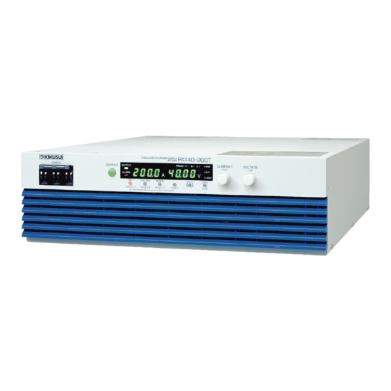
- Page 1 Part No. Z1-004-182, IB015441 Jan. 2009 OPERATION MANUAL Regulated DC Power Supply 4 kW type (three-phase input) PAT20-200T PAT40-100T PAT60-67T PAT160-25T...
- Page 2 If you find any incorrectly arranged or missing pages in this manual, they will be replaced. If the manual gets lost or soiled, a new copy can be provided for a fee. In either case, please contact Kikusui distributor/ agent, and provide the “Kikusui Part No.” given on the cover.
- Page 3 Safety Symbols For the safe use and safe maintenance of this product, the following symbols are used throughout this manual and on the product. Note the meaning of each of the symbols to ensure safe use of the product. (Not all symbols may be used.) Indicates that a high voltage (over 1 000 V) is used here.
-
Page 4: Safety Precautions
Safety Precautions The following safety precautions must be observed to avoid fire hazards, electric shock, accidents, and other failures. Keep them in mind and make sure to observe them. Using the product in a manner that is not specified in this manual may impair the protection functions provided by the product. - Page 5 • To maintain the performance and safe operation of the product, it is recommended that periodic maintenance, inspection, cleaning, and calibration be performed. Service • Kikusui service engineers will perform internal service on the product. If the product needs adjustment or repairs, contact your Kikusui distributor/agent. PAT-T 4kW...
- Page 6 • There is a warning label affixed to the product. If this label tears or falls label off, replace with a new label. If you need a new label, contact your Kikusui agent or distributor. PAT-T Top panel Label PAT-T 4kW...
-
Page 7: How To Read This Manual
How to Read This Manual Introduction Thank you for purchasing the PAT-T Series regulated DC power supply. This manual is intended for first-time users of the PAT. It gives an overview of the PAT and describes various settings, operation, SCPI commands, maintenance, safety precautions, etc. - Page 8 Notations used in the manual • In this manual, the PAT-T Series regulated DC power supply is often simply referred to as “the PAT.” • “PC” in this manual is a generic term for personal computers and workstations. • The following marks are used with the explanations in this manual. WARNING Indicates a potentially hazardous situation which, if ignored, could result in death or serious injury.
-
Page 9: Table Of Contents
Contents Safety Symbols - - - - - - - - - - - - - - - - - - - - - - - - - - - - - - - - - - - - - - - - - - - - - - - - - i Safety Precautions - - - - - - - - - - - - - - - - - - - - - - - - - - - - - - - - - - - - - - - - - - - - - - - ii How to Read This Manual - - - - - - - - - - - - - - - - - - - - - - - - - - - - - - - - - - - - - - - - - v Contents - - - - - - - - - - - - - - - - - - - - - - - - - - - - - - - - - - - - - - - - - - - - - - - - - - - - - vii... - Page 10 Setup and view procedure of CONFIG parameters - - - - - - - - - - - - - - - 4-16 CONFIG parameter details - - - - - - - - - - - - - - - - - - - - - - - - - - - - - - - - 4-17 Preset Memory Function - - - - - - - - - - - - - - - - - - - - - - - - - - - - - - - - - - - - 4-24 Storing the preset memory values - - - - - - - - - - - - - - - - - - - - - - - - - - 4-24 Recalling the preset memory values - - - - - - - - - - - - - - - - - - - - - - - - - 4-25...
- Page 11 VISA Library - - - - - - - - - - - - - - - - - - - - - - - - - - - - - - - - - - - - - - - - - - - - - 7-3 Interface Setup - - - - - - - - - - - - - - - - - - - - - - - - - - - - - - - - - - - - - - - - - - - 7-4 7.4.1 RS232C Control (Standard Equipped) - - - - - - - - - - - - - - - - - - - - - 7-4...
- Page 12 Event status register - - - - - - - - - - - - - - - - - - - - - - - - - - - - - - - - - - - - 7-46 7.16.2 SCPI Register Model - - - - - - - - - - - - - - - - - - - - - - - - - - - - - - - - - 7-47 OPERation status register - - - - - - - - - - - - - - - - - - - - - - - - - - - - - - - - 7-47 QUEStionable status register - - - - - - - - - - - - - - - - - - - - - - - - - - - - - - 7-49...
-
Page 13: Contents By Function
Contents by Function Preparation Situation Heading Page How do I check the accessories. 2.1, “Checking the Package Contents” The installation space is limited. How much space is needed 2.2, “Precautions Concerning Installation” around the air inlet and outlet? How do I connect the AC power supply? 2.5, “Connecting the Power Cable”... -
Page 14: Front Panel
Front panel PAT60-67T REGULATED DC POWER SUPPLY 0-60V 67A PRESET A OUTPUT ALARM LOCK Display and keys REGULATED DC POWER SUPPLY PAT60-67T 0-60V 67A Examples of PAT60-67T PAT-T 4kW... - Page 15 Name Function Page POWER switch Power on/off lever Raise the lever to turn the power on ( ). Lower to turn the power off ( +STORE To change the phase input mode to the single-phase input, press the POWER switch with pressing the STORE key. OUTPUTswitch Output on/off switch.
-
Page 16: Rear Panel
Rear panel 22 23 Name Function Page Connector for external analog control. Connector for parallel operation. Option slot Slot for installing the optional interface board (GPIB, USB or LAN). A factory option. Chassis terminal Terminal used to ground the output. DC OUTPUT Output terminal. -
Page 17: Chapter 1 General Description
General Description This chapter describes an overview and describes the features. -
Page 18: About This Manual
About This Manual This manual describes the PAT-T Series (4 kW type), regulated DC power supply. Applicable firmware version of the PAT This manual applies to PATs with firmware version 4.0x. p. 2-9 When making an inquiry about the product, please provide us with the following information. - Page 19 ● Power Factor Correction circuit is equipped • Reducing the cost of operation Because of the reactive power is reduced, the power can be used without wasting of power. • Downsized input distribution device The input distribution device (breaker) can be downsized, because the built-in power-factor correction circuit reduces the required input current.
-
Page 20: Options
Options The options listed below are available for the PAT-T Series. For details on the options, contact your Kikusui agent or distributor. ■ Rack mounting option p. 2-5 Product Model Note KRB3-TOS Inch unit size rack EIA standard Rack mount... - Page 21 ■ Power cable (for three-phase input) p. 2-6 A power cable to connect to the input terminal block on the rear panel. Product Model Note Power cable AC8-4P4M-M6C 4 m 4 cores ■ Cable for parallel operation p. 6-4 A cable used when performing parallel operation. Product Model Note...
- Page 22 PAT-T 4kW...
-
Page 23: Chapter 2 Installation And Preparation
Installation and Preparation This chapter describes the procedures of unpacking and preparation of the PAT before use. -
Page 24: Checking The Package Contents
When you receive the product, check that all accessories are included and that the accessories have not been damaged during transportation. If any of the accessories are damaged or missing, contact your Kikusui agent or distributor. We recommend that all packing materials be saved, in case the product needs to be transported at a later date. -
Page 25: Precautions Concerning Installation
However, operation in such environments may be possible through alteration. If you want to use the PAT in such environments, consult your Kikusui agent or distributor. ●... -
Page 26: Precautions To Be Taken When Moving The Product
● Do not install the product on an inclined surface or location subject to vibrations. The product may fall or tip over causing damages and injuries. ● Do not use the product in a location where strong magnetic or electric fields are nearby or a location where large amount of distortion and noise is present on the input power supply waveform. -
Page 27: Rack Mounting The Product
Rack Mounting the Product Remove the rubber feet before rack mounting the product to a frame. Fig.2-2 shows how to remove the rubber feet. For details on rack mounting, see the KRB3-TOS or KRB150-TOS Operation p. 1-4 Manual. Install the suitable support angles applying to the used rack system to support the instrument. -
Page 28: Connecting The Power Cable
Connecting the Power Cable This product is designed as an equipment of IEC Overvoltage Category II (energy- consuming equipment supplied from the fixed installation). This product does not come with a power cable. In case the optional power cable p. 1-5 (AC8-4P4M-M6C) for three-phase input is used, attach crimping terminals that comply with the terminal screws on the switchboard and connect the power cable firmly so that it does not come loose. -
Page 29: (Three-Phase Input Mode) Connection Procedure
WARNING Possible electric shock. A maximum current of 17 A in the three-phase input mode and 22 A in the single-phase input mode flows in the PAT at the rated load. When switching the mode from the three-phase input mode to the single-phase input mode, Be sure to use the appropriate type of power cable as specified following instruction and refer to the connection procedure for the single-phase input mode. -
Page 30: (Single-Phase Input Mode) Connection Procedure
(Single-phase input Mode) Connection procedure WARNING Possible electric shock. When connecting the input power in single-phase input mode, the voltage around 100 V to 150 V are applied to the U terminal (the terminal used for the three-phase input mode) on the input terminal board. -
Page 31: Turning On
Precautions Concerning Grounding (Earth) Be sure to ground the product for your safety. Make sure to connect the GND terminal of the AC INPUT terminal block to the GND terminal of the switchboard. Turning On Switching the phase input mode (Three phase input/Single phase input) To confirm the status and the setting of phase input mode (three phase input or p. - Page 32 If the error is displayed after turning the power on If front panel display shows indicated in Table 2-1 after power-on, follow the corresponding remedy. If the remedy does not correct the problem, contact your Kikusui agent or distributor. Table 2-1 Panel display during and after power-on...
- Page 33 Turning the POWER switch off Lower the POWER switch lever to turn it off. When the POWER switch is turned off, the front panel display shows the characters indicated in the following figure for about 10 to 15 seconds. PRESET A OUTPUT ALARM LOCK...
- Page 34 2-12 PAT-T 4kW...
-
Page 35: Chapter 3 Connecting The Load
Connecting the Load This chapter describes the consideration to be given to the load, explains how to connect the load wires, and explains how to connect to the output terminals. -
Page 36: Load Considerations
Load Considerations Note that the output will become unstable if the following types of loads are connected. Load with peaks and pulse-shaped current The PAT indicates only mean values. Even when the indicated value is less than the preset current value, the peak values may actually exceed the preset current value. If this happens, the PAT is instantaneously put into constant-current operation mode, and the output voltage drops accordingly. - Page 37 Load with accumulated energy Connecting a load with accumulated energy, such as a battery, to the PAT may cause current to flow from the load to the internal circuit of the PAT. This current may damage the PAT or reduce the life of the battery. For this type of loads, connect a reverse-current-prevention diode (D ) between the PAT and the load in series as shown in Fig.3-4.
-
Page 38: Load Cable
Load Cable WARNING To prevent the possibility of fire. • Use a load cable with sufficient current capacity with respect to the rated output current of the PAT. • The output terminal and its area nearby gets very high temperature, use the cable with sufficient heat resistance higher than 85 °... - Page 39 However, installing the + (pos.) and - (neg.) output wires of the load cable side by side or bundling them together is more effective against unwanted noise. The Kikusui-recommended currents shown in Table 3-1 are allowable current values that have been reduced in consideration of the potential bundling of load cables. Use these values as a guideline when connecting load cables.
-
Page 40: Connecting To The Output Terminal
Connecting to the Output terminal WARNING Possible electric shock. • Be sure to turn the POWER switch off before touching the output terminal. • Be sure to attach the OUTPUT terminal cover after wiring the load. Connection procedure After the installation of the OUTPUT terminal cover for the output terminal, the p. - Page 41 Connection preparation Turn the POWER switch off. Using the chassis connection wire set that comes with the package, connect the chassis terminal to either the negative or positive DC output terminal. The output terminal has a hole used to connect the chassis connection cable that comes with the package.
- Page 42 Install the OUTPUT terminal cover on the rear panel. Uses the attached screws to install the OUTPUT terminal cover firmly and make sure they are not loosen. Screw Washer OUTPUT terminal cover Fig.3-9 Attachment of the OUTPUT terminal cover PAT-T 4kW...
-
Page 43: Chapter 4 Basic Operation
Basic Operation This chapter describes how to turn on/off the output and the basic operations that you can carry out from the front panel. -
Page 44: Phase Input Mode
Phase input mode (Single-phase input, Three-phase input) The input power mode of the PAT (4 kW type) can be switched to either three-phase input or the single-phase input. Before starting the operation, confirm the status of phase input mode. To verify the p. -
Page 45: Measured Value Display And Setting Display (Setting The Output Voltage And Output Current)
Measured Value Display and Setting Display (Setting the Output Voltage and Output Current) The panel display has two modes. One mode displays the measured values of the output voltage and output current, and the other mode displays the settings. These two modes can be distinguished by the on/off state of the SET, OVP•OCP, and CONFIG keys. -
Page 46: Output Operation
• Setting display of the overvoltage and overcurrent protection Press the OVP•OCP key. The key illuminates. The present overvoltage and overcurrent settings are displayed. PRESET A OUTPUT ALARM LOCK Lights on Fig.4-3 Setting display example of the overvoltage and overcurrent protection •... - Page 47 If the condition above occurs and you are unable to change any of the settings, turn p. 4-29 the POWER switch on while holding down the SHIFT key to reset the PAT to factory default settings. CAUTION • If the OVP/OCP settings are not appropriate when you change the load, the load may break.
-
Page 48: Constant Voltage (Cv) And Constant Current (Cc) Power Supplies
Constant Voltage (CV) and Constant Current (CC) Power Supplies The PAT has a constant voltage power supply function that maintains the output voltage at a constant level and a constant current power supply function that maintains the output current at a constant level even when the load changes. The condition in which the PAT is operating as a constant voltage power supply is called the constant voltage (CV) mode. - Page 49 When operating in CC mode, the output current is maintained at the preset current. × Output voltage V is determined by the relationship defined by the equation V = Is . It is a voltage less than voltage limit Vs. In this mode, the actual voltage that is applied is not necessarily equal to the specified value.
-
Page 50: Using The Pat As A Cv Or Cc Power Supply (Setting The Output Voltage And Output Current)
Using the PAT as a CV or CC Power Supply (Setting the Output Voltage and Output Current) When using the PAT as a constant voltage power supply, the preset current is the limit that can flow through the load. When using the PAT as a constant current power supply, the preset voltage is the limit that can be applied to the load. -
Page 51: Protection Functions And Alarms
Fine adjustment function This function increases the resolution of the VOLTAGE and CURRENT knobs. By turning the VOLTAGE or CURRENT knob while holding down the SHIFT key, you can set the value using finer resolution. The display resolution of the preset voltage and preset current does not change even if you use the fine adjustment function. -
Page 52: Overvoltage Protection (Ovp) And Overcurrent Protection (Ocp)
If you cannot clear the alarm even when all of the causes of the alarm occurrence are eliminated, the PAT may have malfunctioned. If this happens, stop using the PAT and contact your Kikusui agent or distributor. The cause of the alarm occurrences are described in the protection functions. -
Page 53: Ovp And Ocp Trip Point Settings
• When the phase input mode is changed to the single-phase input mode from the three-phase input mode, the setting value of the output current and the overcurrent protection (OCP) is limited to 75 % of the rated value of output current and the overcurrent protection of the three-phase input mode. -
Page 54: Checking The Ovp Or Ocp Operation
Checking the OVP or OCP operation The OVP or OCP is a function for protecting the load. Once you set the OVP or OCP trip point, check that the OVP or OCP works before you connect the load by carrying out the procedure below. If the voltage limit setting is enabled in the CONFIG settings (CF29: ON), the output voltage cannot be set higher than the OVP trip point. -
Page 55: Other Protection Functions
Turn the CURRENT knob slowly clockwise. When the setting value of output current exceeds OCP trip point, the ALARM LED on the front panel display illuminates and either of the POWER switch or the output will be turned off (Depending on the CONFIG settings). When the POWER switch is turned off, the ALARM LED illuminates even the power turns off, and the Power off display of the over current protection (OCP) will be displayed for about 10 to 15 seconds. - Page 56 Fan failure protection (FAN) This function is activated when the fan rotation drops to an abnormal level, and the output turns off. PRESET A OUTPUT ALARM LOCK Fig.4-14 Alarm display of fan failure protection (FAN) Incorrect sensing connection protection (SENSE) This function is activated when the remote sensing wires are connected with the polarity reversed of + (pos.) and - (neg.), and the output turns off.
-
Page 57: Config Settings
CONFIG Settings CONFIG settings are used to set the system configuration of the PAT. You can set or display the parameters in Table 4-1 in the CONFIG settings. On the top panel of the PAT is a label that indicates a list of CONFIG parameters and settings. Table 4-1 CONFIG parameters Parameter... -
Page 58: Setup And View Procedure Of Config Parameters
Setup and view procedure of CONFIG parameters CF01, CF02, CF50, CF52, CF53 and CF57 to CF61 are parameters only for viewing the status. You cannot set them. CF50 to CF61 appear only when the option board is installed. The display of the setting varies depending on the interface option. -
Page 59: Config Parameter Details
CONFIG parameter details CF01 Alarm cause display Displays the cause of the alarm occurrence (while the ALARM LED is illuminated). If there are multiple causes, the sum of each cause is displayed. Display Description Not an alarm condition (ALARM LED is off) Overvoltage protection (OVP) Overcurrent protection (OCP) overheat protection (OHP) - Page 60 CF12 Preset recall setting while locked Sets whether preset memory values can be recalled even when the lock function is p. 4-25 enabled. Settings Description Able to recall preset memory values in the locked condition Unable to recall preset memory values in the locked condition (factory default) CF13 Communication error display setting Sets whether to display communication errors by performing a device trace.
- Page 61 CF22 External control logic setting of the output on/off Sets the logic used to control the output on/off using an external contact (J1 p. 5-17 connector). Cannot be set when the output is on. Select “H” when not controlling the output on/off with an external contact. Settings Description Turn the output on with a high signal (factory default)
- Page 62 CF27 Breaker trip setting when the shutdown signal is applied Sets whether to trip the breaker (turn the POWER switch off) when an external p. 4-14 shutdown (SD) signal is applied. The setting is possible even when the product is used as a slave unit.
- Page 63 CF31 Phase input mode setting (three-phase input mode or single-phase input mode) Sets the phase input mode. This setting is possible even when the product is used as a slave unit in Master-Slave parallel operation. PRESET A OUTPUT ALARM LOCK Fig.4-20 Three-phase input mode PRESET A OUTPUT...
- Page 64 CF43 RS232C flow control setting Sets whether to perform flow control of RS232C. The setting is possible even when p. 7-4 the product is used as a slave unit. Settings Description Disable flow control Enable flow control (factory default) CF50 Interface version display Displays the version of the factory option interface.
- Page 65 When the USB interface is installed Settings Description 232C Use RS232C for the remote interface Use USB for the remote interface (factory default) When the LAN interface is installed Settings Description 232C Use RS232C for the remote interface Use LAN for the remote interface (factory default) CF55 DHCP setting p.
-
Page 66: Preset Memory Function
CF61 LAN status display Display the status of the LAN interface. Displayed only when the factory option LAN interface is installed. Display Description Stby Stand by state (the LAN can not be used) nFLt No fault state (the LAN is functioned properly) Fault state (the LAN is not functioned properly) Display identifying the LAN Preset Memory Function... -
Page 67: Recalling The Preset Memory Values
Recalling the preset memory values Press the SET key. The SET key LED illuminates, and the specified voltage and current are shown on the panel. While holding down the SHIFT key, press the RECALL key in which the preset memory values you want to recall is stored. The LED of the recalled preset memory values (PRESET A, B, or C) illuminates. -
Page 68: 4.10 Switching From Remote To Local Mode
■ Setting Set all the required parameters such as the output voltage and output current. Press the LOCK (SHIFT+LOCAL) key. The LOCK LED on the display illuminates, and the lock is enabled. ■ Release To release the lock function, hold down LOCK (SHIFT+LOCAL) key until the LOCK LED on the display turns off. -
Page 69: Connection Of The Sensing Cable
Connection of the sensing cable WARNING Possible electric shock or damage to the internal circuitry. • Never wire the cable to the sensing terminals while the POWER switch is turned on. • For sensing cables, use cables with a higher voltage rating than the isolation voltage of the PAT. - Page 70 Output terminal Chassis terminal Load – Connect an – electrolytic capacitor as necessary. Sensing terminal Sensing switch 2-core shielded wire Fig.4-26 Remote sensing connection Turn the POWER switch off. Turn on the sensing switch on the rear panel. As shown in Fig.4-26, connect the sensing cable between the sensing terminal and the load terminal.
-
Page 71: 4.12 Factory Default Settings
Load – – –S – Fig.4-27 On/Off using the mechanical switch 4.12 Factory Default Settings Turning ON the POWER switch while holding down the SHIFT key initializes the settings to factory default. Carry out this operation when you want to reset all settings to factory default values. - Page 72 CF28 Breaker trip setting when the OVP or OFF (not trip) OCP is activated CF29 Voltage limit setting OFF (not limit) CF30 Current limit setting OFF (not limit) CF31 PHASE SELECT 3PHA (three-phase input) CF40 RS232C data rate setting 19.2 (kbit/s) CF41 RS232C data length setting 8 bit...
-
Page 73: Chapter 5 External Control
External Control This chapter describes external analog control and remote monitoring using the J1 connector. -
Page 74: Overview Of External Control
At the factory shipment, the protection socket is attached to the J1 connector. Keep this protection socket and be sure to attach when the J1 connector is not used. If the protection socket is damaged or lost, contact Kikusui distributor/agent. [84-49-0110] Fig.5-2... - Page 75 Table 5-1 Connector parts by Omron needed to connect the J1 connectorJ1 Product Model Kikusui parts no. Notes Single contact connection tool XY2B-7006 Y2-070-001 Not included. Contact removal tool XY2E-0001 Y2-070-002 Not included. Pin (contact) XG5W-0031 84-49-0100 Recommended wire size AWG24 (UL-1061).
- Page 76 Table 5-2 connector pin arrangement Pin No. Signal Name Description STATUS COM Common for status signals from pin 3 through 7. STATUS COM Common for status signals from pin 3 through 7. PWR ON/OFF PWR ON STATUS (CF23: 0): Output a low level signal while the power is on. PWR OFF STATUS (CF23: 1): Output a low level signal when the power is off.
-
Page 77: Output Terminal Insulation
Output Terminal Insulation Note the following points and insulate the output terminals. WARNING • Possible electric shock. For safety reasons, even if the output terminal is grounded, make sure the insulation capacity of the output terminal (including the sensing terminal) is greater than the isolation voltage of the PAT. -
Page 78: When The Output Terminal Is Not Grounded (Floating)
5.3.1 When the Output Terminal Is Not Grounded (Floating) The output terminal of the PAT is isolated from the protective conductor terminal. By connecting the GND wire of the power cable to the ground terminal of the switchboard, the chassis of the PAT is set to ground potential as shown in Fig.5-3. Pins 10 through 26 of the J1 connector on the rear panel (for external control and output monitoring) are at approximately the same potential as the - (neg.) output terminal of the PAT. -
Page 79: When The Output Terminal Is Grounded
5.3.2 When the Output Terminal Is Grounded If the positive output terminal is connected to the chassis terminal, the terminal is at ground potential as shown in Fig.5-4. The cable and load that are connected to the output terminal (including the sensing terminal) will only require an insulation capacity that is greater than the maximum output voltage of the PAT with respect to the chassis. - Page 80 When using the external voltage (Vext) Connect the wires so that the output is not shorted as shown in Fig.5-5 and Fig.5-6. CAUTION The signal wire may burn out. • The signal wire may burn out. Leave the Vext output floating. •...
-
Page 81: Controlling The Output Voltage
Controlling the Output Voltage This section explains the method used to control the output voltage using an external voltage (Vext) in the range 0 V to approx. 10 V or an external resistor (Rext) in the range 0 kΩ to approx. 10 kΩ. It is about 5 ms to change the output voltage from the time when the input value of the external voltage or external resistance were changed. - Page 82 External voltage (Vext) connection Use a low-noise and stable voltage source for Vext. The noise in Vext is multiplied by the amplification factor of the PAT and appears at the output. Thus, the output ripple noise may not meet the PAT’s specifications. To minimize the influence of noise on the output, use a two-core shielded wire or a twisted-pair wire to connect the control terminals and Vext.
-
Page 83: External Resistance (Rext) Control
5.4.2 External Resistance (Rext) Control To control the output voltage using Rext, select the CV control source in the p. 4-18 CONFIG settings from the following two modes. Ω → • External resistance control 10 k MAX OUT (CF20: 2) The output voltage (Eo) varies in the range of 0 to the rated output voltage Ω... - Page 84 External resistance (Rext) connection For Rext, use a 1/2 W or larger metal film or wire-wound type resistor with good temperature coefficient and small aging effect. To minimize the influence of noise on the output, use a two-core shielded wire or a twisted-pair wire to connect the control terminals and Rext.
-
Page 85: Controlling The Output Current
Controlling the Output Current This section explains the method used to control the output current using an external voltage (Vext) in the range 0 V to approx. 10 V or an external resistor (Rext) in the Ω Ω range 0 k to approx. - Page 86 External voltage (Vext) connection Use a low-noise and stable voltage source for Vext. The noise in Vext is multiplied by the amplification factor of the PAT and appears at the PAT output. Thus, the output ripple noise may not meet the PAT’s specifications. To minimize the influence of noise on the output, use a two-core shielded wire or a twisted-pair wire to connect the control terminals and Vext.
-
Page 87: External Resistance (Rext) Control
5.5.2 External Resistance (Rext) Control To control the output current using Rext, select the CC control source in the p. 4-18 CONFIG settings from the following two modes. Ω → • External resistance control 10 k MAX OUT (CF21: 2) The output current (Io) varies in the range of 0 to the rated output current (Irtg) by setting the external resistance (Rext) in the range of 0 kΩ... - Page 88 External resistance (Rext) connection For Rext, use a 1/2 W or larger metal film or wire-wound type resistor with good temperature coefficient and small aging effect. To minimize the influence of noise on the output, use a two-core shielded wire or a twisted-pair wire to connect the control terminals and Rext.
-
Page 89: Controlling The Output On/Off
Controlling the Output On/Off This section explains the method used to control the on/off of the output by connecting an external contact. WARNING Possible electric shock. • The insulation of the external contact (S) and the connected cable should be greater than the isolation voltage of the PAT. For the isolation voltage of each model, see Chapter 9, “Specifications.”... - Page 90 External contact connection. Pins 13 and 14 of the J1 connector are used. The release voltage across pins 13 and 14 is approx. 5 V maximum, and the short circuit current is approx. 500 μA maximum. (The internal circuit is pulled up to 5 V through 10 kΩ.) Use parts with a contact rating of 5 Vdc and 0.5 mA for the external contact.
-
Page 91: Shutdown Control Using External Contact
Shutdown Control Using External Contact This section explains the method used to trip the breaker (turn the POWER switch off) or turn the output off using external contact. WARNING Possible electric shock. • The insulation of the external contact (S) and the connected cable should be greater than the isolation voltage of the PAT. - Page 92 Shutdown control connection Pins 11 and 12 of the J1 connector are used. The release voltage across pins 11 and 12 is approx. 5 V maximum, and the short circuit current is approx. 500 μA maximum. (The internal circuit is pulled up to 5 V through 10 kΩ.) Use parts with a contact rating of 5 Vdc and 0.5 mA for the external contact.
-
Page 93: External Monitoring
External Monitoring External monitoring of the output voltage and output current The J1 connector consists of monitor outputs for output voltage and output current. Table 5-4 Monitor output of output voltage and output current Pin No. Signal name Description Common for remote control input 15 and 17 A COM Common terminal of the output monitor... -
Page 94: External Monitoring Of The Operation Mode
External monitoring of the operation mode The J1 connector consists of status outputs that can be used to externally monitor the operating condition of the PAT. The status outputs consist of the following five items. The outputs are open collector outputs of photocouplers; they are insulated from the internal circuits of the PAT. -
Page 95: Chapter 6 Parallel/Series Operation
Parallel/Series Operation This chapter describes the functions of the master-slave series and parallel operations as well as the connection, setup, and operation procedures. -
Page 96: Master-Slave Parallel Operation
Master-Slave Parallel Operation In Master-Slave parallel operation, the system is required to consist of same model for all units and one of the PATs is made a master unit and connected to all other PATs as slave units. The master is used to control the entire system. The output current can be expanded using master-slave parallel operation (maximum ×... - Page 97 Fig.6-1 Panel display example during parallel operation (examples of PAT60-67T X 2 units) Remote sensing p. 4-26 Available only on the master unit. External control Chapter 5 Available only on the master unit. External monitoring p. 5-21 • External monitoring of output voltage (V MON) Can be monitored on the master unit.
-
Page 98: Connection (Parallel Operation)
At the factory shipment, the protection socket is attached to the J1/J2 connector. Keep this protection socket and be sure to attach when the J1/J2 connector is not used. If the protection socket is damaged or lost, contact Kikusui distributor/agent. [84-49-0110] Fig.6-3... -
Page 99: Connecting The Load (Parallel Operation)
Connect the J2 connector on the rear panel of the master unit to the J1 connector on the rear panel of slave unit 1 using the parallel operation power cable (PC01-PAT). If you are not using the PC01-PAT, connect pins 10 to 14 and 24 to 26. Connect the J2 connector on the rear panel of slave unit 1 to the J1 connector on the rear panel of slave unit 2 using the parallel operation power cable (PC01-PAT). -
Page 100: Master-Slave Parallel Operation Setup
Turn off the POWER switches on all power supply units to be connected in parallel. Remove the OUTPUT terminal cover. p. 3-6 Connect the load wires to the output terminals of the master and slave p. 3-4 units. As shown in Fig.6-5, connect the load wires of the master and slave units to the load or the relay terminal block. -
Page 101: Starting The Master-Slave Parallel Operation
Setting the voltage and current The voltage and current are set on the master unit. The total value of the master and p. 6-2 slave units are delivered for the current. When the setting number of units is set by the config setting (CF24) under the master-slave parallel operation, the maximum output current value (Three-phase input mode : 105 % of the rating of the single unit X number of units connected in parallel operation, Single-phase input mode : 105 % of the rating of the single unit... -
Page 102: Series Operation
Turning the power off Turn off the POWER switch of the slave units. Turn off the POWER switch of the master unit. CAUTION • When turning the POWER switch off and then back on, allow at least 10 seconds after the fan stops. Repeated on/off of the POWER switch at short intervals can cause damage to the inrush current limiter and shorten the service life of the POWER switch and internal input fuse. - Page 103 Remote sensing Cannot be used. External control Chapter 5 Can be used. External monitoring p. 5-21 WARNING • When monitoring the output voltage or current during series operation, the common electric potential of the monitor signal of unit 1 and unit 2 is different. •...
-
Page 104: Load Connection (Series Operation)
6.2.2 Load Connection (Series Operation) WARNING • Possible electric shock. Be sure to turn the POWER switch off before touching the output terminal. Be sure to attach the OUTPUT terminal cover after wiring the load. Load or relay terminal block Output terminal Chassis terminal Unit 1... -
Page 105: Starting The Series Operation
Setting the overvoltage protection (OVP) and overcurrent protection (OCP) Overvoltage protection (OVP) and overcurrent protection (OCP) must be configured p. 4-11 on each unit when carrying out series operation. Set the same values on each unit. 6.2.4 Starting the Series Operation Turning the power on/off Turn on/off the POWER switches on unit 1 and unit 2. - Page 106 6-12 PAT-T 4kW...
-
Page 107: Chapter 7 Remote Control
Remote Control This chapter describes an overview of the remote control function and explains the SCPI command structure, syntax, details of each command, registers, and so on used in the remote control. -
Page 108: Remote Control Overview
Remote Control Overview In addition to using the front panel, the PAT can be controlled remotely using the following interfaces. • RS232C interface • GPIB interface (factory option) • USB interface (factory option) • LAN interface (factory option) The PAT is equipped with RS232C as standard. If the factory option interface board is installed, you can use GPIB, USB or LAN. -
Page 109: Visa Library
KI-VISA is not required if NI-VISA or Agilent VISA is already installed. It may cause possible malfunction. KI-VISA is Kikusui’s original VISA library that supports VXIplug&play VISA Specifications 3.0. The newest version can be downloaded from Download service of Kikusui website (http://www.kikusui.co.jp/en/download/). -
Page 110: Interface Setup
Interface Setup 7.4.1 RS232C Control (Standard Equipped) RS232C connection The RS232C port on the PAT is a standard D-sub 9-pin male connector. Check that the POWER switches of the PAT and computer are off, and connect the PAT to the computer using a standard cross cable (null modem cable). Use a D-sub 9-pin female-to-female AT type for the cross cable. - Page 111 Protocol Table 7-1 shows the RS232C protocol. Underline indicates factory default condition. The value inside the parentheses is the CONFIG setting value. Table 7-1 RS232C protocol Item Setting Connector 9-pin D-sub terminal on the rear panel Baudrate 1 200 bps/ 2 400 bps/ 4 800 bps/ 9 600 bps/ 19 200 bps/ 38400 bps (1.2/2.4/4.8/9.6/19.2/38.4) Data length (8 bits or 7 bits)
-
Page 112: Gpib Interface (Option)
7.4.2 GPIB Interface (Option) This interface valid only when the factory option GPIB interface board is installed. GPIB connection Use a standard IEEE488 cable to connect the PAT to the computer. GPIB configuration Select GPIB (CF54: GPIb) in the CONFIG settings. p. -
Page 113: Usb Interface (Option)
7.4.3 USB Interface (Option) This interface valid only when the factory option USB interface board is installed. A device driver supporting USB T&M Class (USBTMC) is required to control the p. 7-3 PAT through the USB interface. The USBTMC driver is automatically installed by the VISA library. -
Page 114: Lan Interface (Option)
7.4.4 LAN Interface (Option) This interface valid only when the factory option LAN interface board is installed. When the product is controlled by the LAN interface, middleware which applies to p. 7-3 the VXI-11 protocol is required. The middleware is automatically installed by VISA library. - Page 115 NON AUTO-MDIX REBOOT switch REBOOT LAN reset switch LAN RESET NB01334-1 Push here by using a fiine point tool Fig.7-3 REBOOT switch and LAN reset switch ■ REBOOT switch When you keep pressing the "REBOOT" switch for more than 2 seconds, the LAN will reboot.
-
Page 116: Overview Of Messages
Overview of Messages The information that is exchanged between the computer and the PAT is called a message. The PAT uses the SCPI language for the messages. There are two types of messages, commands that are sent from the computer to the PAT and responses that are sent from the PAT to the computer. -
Page 117: Scpi Command Syntax
7.5.1 SCPI Command Syntax Command syntax This manual denotes SCPI commands using the following format. (Example) [SOURce:]CURRent[:LEVel][:IMMediate][:AMPLitude] {<current>|MINimum|MAXimum} • There are two forms of SCPI commands, the long form in which the command is written out in its entirety and the short form in which the letters written in lowercase are omitted. - Page 118 Special symbols and characters Special symbols and characters used in this manual to describe SCPI commands are defined as indicated in Table 7-4. Table 7-4 Definitions of special symbols and characters Symbols or Description characters Characters strings inside the < and > symbols indicate program data. <...
-
Page 119: Parameters
7.5.2 Parameters The parameter format of SCPI is derived from the program parameter format defined in IEEE 488.2. The representation system of the program data that is used on the PAT is indicated below. Non-numeric parameters The PAT uses the following three types of non-numeric parameters. Table 7-5 Non-numeric parameters Symbols or characters... - Page 120 Special form numeric parameter The special form numeric parameters MINimum and MAXimum can be used as substitutes for limit values when the parameter is numeric. In the example below, the overcurrent protection is set to the minimum value. CURRent:PROTection MINimum The minimum and maximum values can be inquired for most parameters using queries.
-
Page 121: Command Description In This Manual
Command Description in This Manual This manual describes the commands in the following manner. Attach the value you want to specify after the command and send the command. To set the overcurrent protection to 100 A, send CURR:PROT 100. CURR :PR OT The parameters are listed. -
Page 122: Ieee488.2 Common Commands
IEEE488.2 Common Commands *CLS Clears all event registers including the status byte, event status, and error queue. Command p. 7-43 *CLS *ESE Sets the event status enable register that is counted by the event summary bit (ESB) p. 7-46 of the status byte. Command *ESE <NR1>... - Page 123 Response The response to *IDN? is indicated below. (Example) For PAT20-400T with a serial number AB123456 and firmware version 1.00 Returns KIKUSUI,PAT20-400T,AB123456,1.00. *OPC Sets the OPC bit (bit 0) of the event status register when all of the command ...
- Page 124 *PSC Sets whether to clear the event status enable register and the service request enable register when the POWER switch is turned on (power-on status). IEEE 488.2-1992 Section 10.25 Command *PSC <NR1> *PSC? Parameter Value: Does not clear the *ESE and *SRE settings when the POWER switch is turned on.
- Page 125 *SRE Sets the service request enable register. The service request enable register is used to select the summary messages in the status byte register that will be able to perform service requests. To clear the service request enable register, send *SRE 0. If the register is cleared, service requests cannot be generated by status information.
- Page 126 *TRG Trigger command. IEEE 488.2-1992 This is a substitute command for the IEEE488.1 get message (Group Execute Section 10.37 Trigger). If the PAT is not in a condition to accept triggers, an SCPI error (-211, “Trigger ignored”) occurs. Command *TRG *TST This command is to perform the self-test, however, the PAT does not equip this...
-
Page 127: Output Setting
Output Setting Output on / off OUTP Turn the output on/off. The condition set by the Output on/off Delay function is disabled. Command OUTPut[:STATe][:IMMediate] {ON|OFF|1|0} OUTPut[:STATe][:IMMediate]? Parameter Value: ON(1) Output on OFF(0) Output off (default) For the setting that is applied when *RST is sent, see Table A-16. Response Returns the output status in the NR1 form in response to OUTP?. -
Page 128: Voltage Settings
Voltage Settings VOLT Sets the voltage. Command [SOURce:]VOLTage[:LEVel][:IMMediate][:AMPLitude] {<numeric>|MIN|MAX} [SOURce:]VOLTage[:LEVel][:IMMediate][:AMPLitude]? {MIN|MAX} Parameter Value: 0 % to 105 % of the rated output voltage (The default value is 0 % of the rated output voltage.) SCPI error (-221, “Settings conflict”) occurs VOLT:EXT:SOUR is not set to NONE. -
Page 129: Measurement Operation Settings
Response Returns the current setting in the NR3 form in response to CURR?. If the current value is set using external input, the specified current is returned. Measurement Operation Settings For the procedure to set the measurement operation, See “Measurement operation” on page 7-39. -
Page 130: Overcurrent Protection Settings
VOLT:LIM:AUTO Sets whether to enable the voltage limit setting. If enabled, the voltage limit setting is automatically set to approximately 95 % of the OVP trip point. This cannot be set when the output is on. Command [SOURce:]VOLTage:LIMit:AUTO {ON|OFF|1|0} [SOURce:]VOLTage:LIMit:AUTO? Parameter Value: ON (1) -
Page 131: Current Setting Limit
Current setting limit • When the phase input mode is changed to the single-phase input mode from the three-phase input mode, the setting value of the output current and the overcurrent protection (OCP) is limited to 75 % of the rated value of output current and the overcurrent protection (OCP) of the three-phase input mode. -
Page 132: Operation When A Protection Function Is Activated
Operation when a protection function is activated SYST:CONF:BTR:PROT Sets whether to trip the breaker (turn the POWER switch off) when the overvoltage protection (OVP) or overcurrent protection (OCP) is activated. Command SYSTem:CONFigure:BTRip:PROTection {ON|OFF|1|0} SYSTem:CONFigure:BTRip:PROTection? Parameter Value: ON(1) Trip (turn the POWER switch off) OFF(0) Not trip (turn the output off) (default) Response... -
Page 133: 7.12 Other System Configuration
7.12 Other System Configuration Sets the phase input mode (Three-phase input/Single-phase input mode) SYST:CONF:SPH Sets the phase input mode (Three-phase input/Single-phase input mode) Command SYSTem:CONFigure:SPHase {ON|OFF|1|0} SYSTem:CONFigure:SPHase? Parameter Value: ON(1) Select the Single-phase input mode OFF(0) Select the Three-phase input mode (default) Response Returns the setting status of phase input mode (Single-phase input/Three-phase input mode) in the NR1 form in response to SYST:CONF:SPH? -
Page 134: Controlling The Constant Voltage/Current
Controlling the constant voltage/current VOLT:EXT:SOUR Sets the constant voltage control mode. This cannot be set when the output is on. Command [SOURce:]VOLTage:EXTernal:SOURce {NONE|VOLTage|RESistance|IRESistance} [SOURce:]VOLTage:EXTernal:SOURce? Parameter Value: NONE Panel control (default) VOLTage External voltage control RESistance External resistance control 10 kΩ → MAX OUT IRESistance External resistance control 10 kΩ... -
Page 135: Setting The Breaker Trip
Setting the breaker trip SYST:CONF:BTR Sets the breaker trip (turn the POWER switch off). Command SYSTem:CONFigure:BTRip[:IMMediate] Setting the master-slave parallel operation SYST:CONF:PAR Sets the number of units in Master-Slave Parallel Operation. It enables to set only for the Master unit. It can not be set when the output is turned on. Command SYSTem:CONFigure:PARallel {1|2|3|4|5} SYSTem:CONFigure:PARallel? -
Page 136: Monitoring The Power On/Off Status The The External (J1) Connector
Monitoring the power on/off status the the external (J1) connector SYST:CONF:PST Sets whether to output a low level signal at power on status or power off status when monitoring the power on/off status externally (through the J1 connector). Command SYSTem:CONFigure:PSTatus {NORMal|INVerted} SYSTem:CONFigure:PSTatus? Parameter Value:... -
Page 137: 7.13 Preset Memory Function
7.13 Preset Memory Function This section explains the commands related to the memory functions of the PAT. • When the phase input mode is changed to the single-phase input mode from the three-phase input mode, the setting value of the output current and the overcurrent protection (OCP) is limited to 75 % of the rated value of output current and the overcurrent protection (OCP) of the three-phase input mode. -
Page 138: 7.14 Trigger Function
Response Returns whether recalling of the preset memory is allowed when the keys are locked in the NR1 form in response to MEM:KLOC?. 7.14 Trigger Function Specifies settings related to the trigger function. Setting the trigger The trigger is classified into three sequence groups, TRIGger[:SEQuence[1]], TRIGger:SEQuence2, and TRIGger:SEQuence3. - Page 139 Table 7-8 Responses after sending VOLT 20;:VOLT:TRIG 10 Response VOLT? VOLT:TRIG? Immediately after the setting After a trigger is sent After *RST is sent ABOR is sent before 20 (cancel) sending a trigger Voltage change VOLT 30 is sent before sending a 30 (cancel) trigger VOLT:TRIG...
- Page 140 TRIG:SOUR Sets the condition (trigger source) for actually changing the setting after the sequence 1 group receives INIT:SEQ1 / INIT:NAME TRAN. Command TRIGger[:SEQuence[1]]:SOURce {IMMediate|BUS} TRIGger[:SEQuence[1]]:SOURce? TRIGger[:TRANsient]:SOURce {IMMediate|BUS} TRIGger[:TRANsient]:SOURce? Parameter Value: Starts the setting immediately Wait for a software trigger (*TRG, TRIG, or IEEE488.1 get (Group Execute Trigger)) to change the setting (Default)
-
Page 141: Output On/Off Delay Function (Sequence 2: Output Settings)
7.14.2 Output On/Off Delay Function (Sequence 2: OUTPUT Settings) The sequence 2 group enables the OUTPut on/off delay to be controlled with p. A-20 triggers. OUTP:TRIG Sets whether to turn the output on or off when a trigger is applied. Command OUTPut[:STATe]:TRIGgered {ON|OFF|1|0} OUTPut[:STATe]:TRIGgered? - Page 142 TRIG:SEQ2:DEL:OFF / TRIG:OUTP:DEL:OFF Sets the delay for turning off the output. Command TRIGger:SEQuence2:DELay:OFF {<numeric>|MIN|MAX} TRIGger:SEQuence2:DELay:OFF? TRIGger:OUTPut:DELay:OFF {<numeric>|MIN|MAX} TRIGger:OUTPut:DELay:OFF? Parameter Value: 0.0 to 10.0 0 is no delay (The default value is 0.0) Unit For the setting that is applied when *RST is sent, see Table A-16. Response Returns the delay time until the output is turned off in the NR3 form in response to TRIG:SEQ2:DEL:OFF? / TRIG:OUTP:DEL:OFF?.
-
Page 143: Measurement (Sequence 3: Acquire Settings)
INIT:SEQ2 / INIT:NAME OUTP Starts the trigger function of the sequence 2 group. If TRIG:SEQ2:SOUR or TRIG:OUTP:SOUR is set to IMM, the delay action starts immediately. If set to BUS, the delay action starts after waiting for a software trigger. Command INITiate[:IMMediate]:SEQuence2 INITiate[:IMMediate]:NAME OUTPut... -
Page 144: Sequence Operation Auto Continue Mode
INIT:SEQ3 / INIT:NAME ACQ Clears the present valid measurement data and starts a new measurement. If the trigger source parameter of the sequence 3 group is IMM, the measurement starts immediately. If set to BUS, the measurement starts after waiting for a software trigger. -
Page 145: Clearing The Measurement Data
Parameter Value: ON(1) Auto continue mode on OFF(0) Auto continue mode off (default) For the setting that is applied when *RST is sent, see Table A-16. Response Returns the sequence operation auto continue mode setting in the NR1 form in response to INIT:CONT:SEQ3? / INIT:CONT:NAME ACQ. -
Page 146: 7.14.4 Aborting The Operation
FETC:VOLT / MEAS:VOLT Queries the measured value of the voltage output. Command FETCh[:SCALar]:VOLTage[:DC]? MEASure[:SCALar]:VOLTage[:DC]? Response Returns the measured value of the voltage output in the NR3 form in response to FETC:VOLT? / MEAS:VOLT?. FETC:CURR / MEAS:CURR Queries the measured value of the current output. Command FETCh[:SCALar]:CURRent[:DC]? MEASure[:SCALar]:CURRent[:DC]? -
Page 147: 7.15 System Settings
7.15 System Settings SYST:ERR Reads the oldest error information or event information from the error queue. The error queue can store up to 255 errors. The error queue is cleared using the *CLS command. Command SYSTem:ERRor[:NEXT]? Response Returns the oldest error or event information in the error/event queue in response to SYST:ERR? as follows: (Example) When there is no error or event Returns 0, “No error”. - Page 148 SYST:OPT Queries the hardware interface board that is installed in the PAT. This command is the same as *OPT?. Command SYSTem:OPTion? Response Returns 0 if there is no option installed in response to SYST:OPT?. If the factory option GPIB, USB or LAN interface board is installed, “GPIB”, “USB”...
-
Page 149: 7.16 Status Register And Status Report Function
7.16 Status Register and Status Report Function IEEE488.2 and SCPI registers are used for the status reports. In each SCPI status register, there are sub registers, CONDition register, EVENt register, ENABle register, PTRansition filter, and NTRansition filter. Fig.7-4 shows the SCPI status register structure. The character “+” represents the logic sum of the register bits. - Page 150 1999 SCPI Syntax & Style Over Voltage protection Over Current protection NOT USED POWER switch off Over Heat protection NOT USED Power-line Phase protection SENSing protection FAN protection Bleeder protection UNRegulated Shutdown Alarm NOT USED Instrument SUMmary NOT USED NOT USED NOT USED NOT USED NOT USED...
-
Page 151: 7.16.1 Ieee488.2 Register Model
7.16.1 IEEE488.2 Register Model Status byte register The status byte register stores STB and RQS (MSS) messages as defined by the IEEE488.1 standard. The status byte register can be read using IEEE488.1 serial polling or IEEE488.2 common command *STB?. When serial polling is carried out, bit 6 responds with the request service (RQS). The status byte value is not changed by serial polling. -
Page 152: Event Status Register
Event status register The event status register bits are set when certain events occur during PAT operation. All bits of the event status register are set by the error event queue. The register is defined by the IEEE488.2 standard and is controlled by the IEEE488.2 common commands *ESE, *ESE?, and *ESR?. -
Page 153: 7.16.2 Scpi Register Model
7.16.2 SCPI Register Model OPERation status register The OPERation status register is a 16-bit register which contains information about conditions which are part of the PAT normal operation. Table 7-11 OPERation status register (STATus:OPERation) Bit Name Description Weight NOT USED –... - Page 154 STAT:OPER:COND Queries the condition of the OPERation status register. A query does not clear the contents of the register. Command STATus:OPERation:CONDition? Response Returns the condition of the OPERation status register in the NR1 form. STAT:OPER:ENAB Sets the enable register of the OPERation status register. Command STATus:OPERation:ENABle <NRF>...
-
Page 155: Questionable Status Register
QUEStionable status register The QUEStionable status register is a 16-bit register that stores information related to the questionable events and status during PAT operation. These register bits may indicate problems with the measured data of the PAT. Table 7-12 QUEStionable status register (STATus:QUEStionable) Bit Name Description Weight... - Page 156 STAT:QUES:COND Queries the condition of the QUEStionable status register. A query does not clear the contents of the register. Command STATus:QUEStionable:CONDition? Response Returns the status of the QUEStionable status register in the NR1 form. STAT:QUES:ENAB Sets the enable of the QUEStionable status register. Command STATus:QUEStionable:ENABle <NRF>...
-
Page 157: Preset Status
Preset status STAT:PRES Resets the ENABle, PTRansition, NTRansition filter registers of all status registers (including sub registers) to their default values. Default values: STATus:ENABle = 0x0000 STATus:PTRansition = 0x7FFF STATus:NTRansition = 0x0000 Command STATus:PRESet 7-51 PAT-T 4KW... - Page 158 7-52 PAT-T 4KW...
-
Page 159: Chapter 8 Maintenance
Maintenance This chapter describes maintenance such as cleaning, inspecting, and calibrating. -
Page 160: Inspection
• Tears in the insulation coating may cause electric shock or fire. If a tear is found, stop using it immediately. To purchase accessories or options, contact your Kikusui agent or distributor. Cleaning the Dust Filter Two dust filter sheets are installed on the inside of the louver on the front panel. - Page 161 Remove the upper louver in the same manner as step 1 . Remove the dust filter from the inside of the louver and clean it. There is a hook on the louver tab. Be sure not to get the dust filter caught in the hook when removing the dust filter from the louver.
- Page 162 Attach the upper louver first. The shapes of the upper and lower dust filters are different. The upper dust filter has a cutout. Align the tab on the inner side of the louver to the panel groove and slide the louver to the left to attach it.
-
Page 163: Calibration
The PAT is shipped after carrying out appropriate calibrations. We recommend periodic calibration to maintain the performance over an extended period. For calibration, contact your Kikusui agent or distributor. If you are going to calibrate the PAT yourself, follow the procedures below. -
Page 164: Calibration Procedure
8.3.2 Calibration Procedure Be sure to carry out the calibration items to the last step. If you move to a different type of calibration in the middle of another calibration or if you turn the POWER switch off, the calibration is invalid. WARNING Possible electric shock. - Page 165 Calibration procedure of the output voltage, voltmeter, and the overvoltage protection setting (CAL.1 and CAL.2) Calibrate CAL.1 and CAL.2 consecutively. Output terminal Chassis terminal Fig.8-7 Connection for CAL.1 and CAL.2 Turn the POWER switch off. Connect a DVM to the output terminal. While holding down the SET key, turn on the POWER switch.
- Page 166 Calibration procedure of the output current, ammeter, and the overcurrent protection setting (CAL.3 and CAL.4) Calibrate CAL.3 and CAL.4 consecutively. Shunt Output terminal Chassis terminal Fig.8-8 Connection for CAL.3 and CAL.4 Turn the POWER switch off. Connect a shunt resistor to the output terminal, and connect the DVM to across the shunt resistor.
- Page 167 Calibration procedure of the output voltage control using external voltage (CAL.5) Output terminal 2-core shielded or twisted-pair wire Chassis terminal Vref – Fig.8-9 Connection for CAL.5 Turn the POWER switch off. Connect the voltage source (Vref) to pins 21 and 22 of the J1 connector.
- Page 168 Calibration procedure of the output voltage control using external resistance (CAL.6) Output terminal 2-core shielded or twisted-pair wire Chassis terminal Rref Fig.8-10 Connection for CAL.6 Turn the POWER switch off. Connect the 0 Ω resistor (Rref) to pins 21 and 22 of the J1 connector. While holding down the SET key, turn on the POWER switch.
- Page 169 Calibration procedure of the output current control using external voltage (CAL.7) Output terminal 2-core shielded or twisted-pair wire Chassis terminal Vref – Fig.8-11 Connection for CAL.7 Turn the POWER switch off. Connect the voltage source (Vref) to pins 19 and 20 of the J1 connector.
- Page 170 Calibration procedure of the output current control using external resistance (CAL.8) Output terminal 2-core shielded or twisted-pair wire Chassis terminal Rref Fig.8-12 Connection for CAL.8 Turn the POWER switch off. Connect the 0 Ω resistor (Rref) to pins 19 and 20 of the J1 connector. While holding down the SET key, turn on the POWER switch.
-
Page 171: Specifications
Specifications This chapter describes the specifications and gives the dimensions of the PAT. -
Page 172: Ac Input
10 % of the maximum output voltage or 1 V, whichever is greater, at the rated output current. AC input PAT20-200T PAT40-100T PAT60-67T PAT160-25T Nominal input rating 200 V to 240 V, 50 Hz to 60 Hz... -
Page 173: Output Specifications
Output specifications PAT20-200T PAT40-100T PAT60-67T PAT160-25T Rating Output power three-phase input mode 4 kW single-phase input mode 3 kW Output voltage 20.00 V 40.00 V 60.00 V 160.0 V 200.0 A 100.0 A 67.0 A 25.0 A Output current Voltage... -
Page 174: Display Function
Display function PAT20-200T PAT40-100T PAT60-67T PAT160-25T Voltmeter Maximum display 99.99 999.9 (fixed decimal point) Display accuracy ± (0.2 % of rdng + 5 digits) Ammeter Maximum display 999.9 99.99 (fixed decimal point) Display accuracy ± (0.5 % of rdng + 5 digits) -
Page 175: Protection Functions
Protection functions PAT20-200T PAT40-100T PAT60-67T PAT160-25T Overvoltage protection (OVP) Protection action Turns off the output or trips the breaker (turns the POWER switch off) ALARM LED illuminates. Setting range 10 % to 111.5 % of the rated output voltage Setting accuracy ±... -
Page 176: Output Signals
Output signals PAT20-200T PAT40-100T PAT60-67T PAT160-25T Monitor signal output VMON (Voltage) At rated voltage 10.00 V ± 0.25 V output At 0 V output 0.00 V ± 0.25 V I MON (Current) At rated current output three-phase 10.00 V ± 0.25 V... -
Page 177: Control Functions
Control functions PAT20-200T PAT40-100T PAT60-67T PAT160-25T External control EXT-V CV CONT *2 0 % to 100 % of the rated output voltage (CV external voltage in the range of 0 V to 10 V. control) EXT-R CV CONT (1) 0 % to 100 % of the rated output voltage (CV external resistance in the range of 0 kΩ... -
Page 178: Interface
Interface PAT20-200T PAT40-100T PAT60-67T PAT160-25T Common specifications Software protocol IEEE Std 488.2-1992 Command Complies with the SCPI Specification 1999.0 specifications. language RS232C Hardware Complies with EIA232D. D-SUB 9-pin connector (male) Baud rate: 1 200, 2 400, 4 800, 9 600, 19 200, and 38 400 bps Data length: 7 bits or 8 bits. -
Page 179: General Specifications
General specifications PAT20-200T PAT40-100T PAT60-67T PAT160-25T Weight Approx. 20 kg Approx. 19 kg Approx. 18 kg (main unit only) (Approx. 44 lbs.) (Approx. 42 lbs.) (Approx. 40 lbs.) Dimensions See the outline drawing Environmental conditions Operating conditions Indoor use, Overvoltage Category II Operating temperature 0 °... -
Page 180: Dimensions
Dimensions (16.93) M4 screws for attaching the rubber feet 59.5 (17.72) (12.99) (2.34) (21.65) MAX 440 (17.32) MAX 620 (24.41) MAX 20 (0.79) Unit: mm (inch) Fig.9-1 PAT-T series outline drawing 9-10 PAT-T 4kW... -
Page 181: Appendix
Appendix The appendix contains lists of messages, lists of command errors, Access and operation for the built-in Web site, tutorials, sample programs, and troubleshooting. -
Page 182: Lists Of Messages
SCPI command: Command name in the short form *RST: Yes for commands that are affected by *RST R/W: Query command (R)/set command (W). † : 1, 2, and 3 indicate SCPI standard command, command in review, and KIKUSUI original command, respectively. Table A-1... - Page 183 Table A-5 SOURce subsystem SCPI Command Setting Default Resp. *RST Description † Program header Parameter Unit [SOUR] :VOLT 0 % to 105 % Sets the voltage. [:LEV][:IMM][:AMPL] of the rated output R/W 1 numeric voltage NONE | VOLT | Sets the CV control :EXT:SOUR NONE char...
- Page 184 Table A-6 STATus subsystem SCPI Command Setting Response Description † Program header Parameter STAT :OPER [:EVEN] Event. :COND Register status. :ENAB 0 to 32767 R/W 1 Enable. :PTR 0 to 32767 R/W 1 Positive transition. :NTR 0 to 32767 R/W 1 Negative transition.
- Page 185 Table A-8 TRIGger subsystem SCPI Command Setting Default Resp. Description † *RST Parameter Unit Program header Aborts the operation of all ABOR sequences. INIT [:IMM] TRAN | OUTP| Sequence 1, 2, and 3: :NAME char Starts the trigger function. Sequence 1: Starts the :SEQ1 voltage/current setting trigger function.
- Page 186 Table A-9 IEEE488.2 common commands IEEE488.2 common Parameter Description command *CLS Clears all the event registers. *ESE Sets the event status enable register bits. *ESR Queries the event status register. *IDN Queries the identification string (manufacturer information). Causes the device to generate the operation complete message in the *OPC event status register when all pending selected device operations have been finished.
-
Page 187: A List Of Errors
A List of Errors Command errors An error in the range [ -199, -100 ] indicates that an IEEE 488.2 syntax error has been detected by the instrument’s parser. The occurrence of any error in this class shall cause the Command Error (bit 5) in the event status register to be set. Table A-10 Command errors Error Code Error Message Description... - Page 188 Execution errors An error in the range [-299, -200] indicates that an error has been detected by the instrument’s execution control block. The occurrence of any error in this class shall cause the Execution Error (bit 4) in the event status register to be set. Table A-11 Execution errors Error Code Error Message Description...
- Page 189 Query errors An error in the range [-499, -400] indicates that the output queue control of the instrument has detected a problem with the message exchange protocol described in IEEE 488.2, chapter 6. The occurrence of any error in this class shall cause the Query Error (bit 2) in the event status register to be set.
-
Page 190: Default Conditions
Default Conditions Table A-16 shows how the PAT is set when the *RST command is executed, at the p. 7-18 time of factory shipment, and when the power is turned on. Table A-16 Conditions after sending a *RST and at power-on Setting Setup item Unit... -
Page 191: Processing Time Of Commands
When VISA library is used, there is the function to retrieve the VXI-11 measuring instrument by the application program provided by VISA vendors (National Instruments NI-MAX, Agilent Connection Expert, and Kikusui KI-VISA Instrument Explorer, etc.). Once you click on the web link from the retrieval result, the built-in Web site can be Appx opened. - Page 192 WELCOME page Firstly, WELCOME page is displayed when the built-in Web site is connected. The instrument information, network information, and VISA resource information appear on the display. Click the navigation menu to move to the other page. Change of English/Japanese Display it by the language that clicked.
- Page 193 SECURITY page This page is for the security setting. This page can allow you to set the change of the password protection, and the host limit function by the IP address. The password protection is an effective security features to the Web site. It prevents from being changed inadvertently.
- Page 194 CONTROL page This page can allow you to set up the simple power supply control application program using the JAVA applet. It can set the output of voltage, current and monitor for the measuring value. It is required for the JRE (JAVA runtime environment) to be installed beforehand. This applet can control the output of voltage, current and monitor for the measuring value.
- Page 195 This is firmware update page for the LAN interface. On this page, you can update by downloading the latest firmware version from the download service of our Web site (http://www.kikusui.co.jp/en/download/). For details of updating firmware, refer to the document in the download module.
-
Page 196: Tutorial
Tutorial This section describes the procedures to make measurements through remote control on the PAT. A.6.1 Turning the Power On and Resetting the Instrument When the PAT is turned on, all panel settings are set to the state when it was turned off the last time. -
Page 197: Output Programming
A.6.2 Output Programming Voltage and current The output voltage and output current are controlled by the VOLTage and CURRent commands. The output ON/OFF state is controlled by the OUTPut command. ' Set the voltage to 13.5 V :VOLTage 13.5 ' Set the current to 4.5 A :CURRent 4.5 ' Turn the output on :OUTPut ON... -
Page 198: Using Triggers
Setting the protection functions The PAT provides overvoltage protection (OVP) and overcurrent (OCP) functions that can be configured. The VOLTage:PROTection and CURRent:PROTection commands are used to set the OVP and OCP, respectively. ' Set the OVP to 16 V :VOLTage:PROTection 16.0 ' Set the OCP to 7.5 A :CURRent:PROTection 7.5 If you want to set the OVP or OCP setting to the maximum or minimum value, you... -
Page 199: Setting Changes (Sequence 1: Transient
Setting changes (Sequence 1: TRANsient) Using the TRIGger:SEQuence1 (or TRIGger:TRANsient) subsystem allows the VOLTage and CURRent settings to be synchronized using triggers. This is convenient if you want to synchronize output changes with the action of other instruments such as electronic loads. To reserve triggered settings, use the VOLTage:TRIGgered and FREQuency:TRIGgered commands. -
Page 200: Output On/Off Delay Function (Sequence 2: Output
Output on/off delay function (Sequence 2: OUTPut) The TRIGger:SEQuence2 (or TRIGger:OUTPut) subsystem allows you to use the output on/off delay function. To reserve the operation of the output change using triggers, use the OUTPut:TRIGgered command. :TRIGger:SEQuence2:SOURce BUS ' Set the trigger source to BUS :TRIGger:SEQuence2:DELay:ON 0.5 ' Set the output on delay to 0.5 s :OUTPut:TRIGgered ON... -
Page 201: Measurement (Sequence 3: Acquire
Measurement (Sequence 3: ACQuire) The PAT has the capability to return voltage and current measurement values. The easiest way is use the MEASure commands. The trigger function is not used. The MEASure commands immediately start a new measurement. Simultaneity for multi-item measurements are lost, because each MEASure command starts a new measurement. - Page 202 trigger subsystem goes to the WTG (Waiting For Trigger) state. When a software trigger is applied with the TRIGger:SEQuence3 or *TRG common command, the measurement action is executed. When an ABORt or an equivalent command is sent without executing the trigger, the measurement action is cancelled, and then the trigger subsystem returns to the IDLE state.
-
Page 203: Auto Continue
Auto continue To keep the trigger subsystem initiated for multiple actions without having to send an initiate command for each trigger, use the CONTinuous option. This enables measurement data to be automatically refreshed as if the PAT is operating in local mode. -
Page 204: Status Monitoring
A.6.4 Status Monitoring The PAT has two mandatory SCPI standard registers, STATus:OPERation and STATus:QUEStionable, in addition to the IEEE488.2 standard registers. Register basics All SCPI registers have standard event/filter architecture, employing CONDition, p. 7-43 EVENt, ENABle, and optionally PTRansition and NTRansition. The CONDition and EVENt are read-only registers working as status indicators, and the ENABle, PTRansition and NTRansition are read-write registers working as event and summary filters. - Page 205 PON (Power ON) bit The PON bit (bit 7) in the event status register is set whenever the PAT is turned on. The most common use for the PON is to generate an SRQ at power-on keeping track of unexpected loss of power or power line failure. To do this, follow the steps shown below.
-
Page 206: Error Checking
A.6.5 Error Checking Error/event queue The SCPI specifications define a standard error reporting scheme, Error/Event Queue. This is a FIFO (First In First Out) queue, which records errors and events. The maximum number of errors/events that the PAT can record is 255. Each error/ event can be read with the SYSTem:ERRor query. -
Page 207: Sample Programs
Sample Programs The samples given in this section assumes Microsoft Visual Basic 6.0 for the p. 7-3 development platform and VISA library (VISA COM) for the I/O library. The format of the VISA resource string that is substituted in the variable strVisaAddress varies for GPIB, RS232C, USB and LAN interface. - Page 208 Sample 1 (Voltage and current output and measurement) This sample is an example to query the Output voltage/current value after the output is turned on through the communication by RS232C having with voltage/current setting and overvoltage/overcurrent setting. The queried value will be converted from the text to the numerical value and each of those will be substitute for the variable in double data type.
- Page 209 ' Set the voltage io.WriteString ":VOLT" & Str$(dVolt) ' Set the current io.WriteString ":CURR" & Str$(dCurr) ' Set the overvoltage protection io.WriteString ":VOLT:PROT:LEV" & Str$(dOVP) ' Set the overcurrent protection io.WriteString ":CURR:PROT:LEV" & Str$(dOCP) ' Turn the output on io.WriteString ":OUTP ON" ' Measure the output voltage and current Dim dVoltMeasure As Double Dim dCurrMeasure As Double...
- Page 210 Sample 2 (Voltage and current output and measurement (using triggers)) This sample is an example to change the setting condition from the present voltage/ current setting to the preset value of the trigger voltage/current when *TRG command is sent. It is required to send ":INIT:SEQ1" before the *TRG command is sent.
- Page 211 dVoltTrig = 15 'volts ' trigger voltage setting value : 15V dCurrTrig = 60 'amps ' trigger current setting value : 60A ' Set the immediate voltage io.WriteString ":VOLT" & Str$(dVolt) ' Set the immediate current io.WriteString ":CURR" & Str$(dCurr) ' Set the triggered voltage io.WriteString ":VOLT:TRIG"...
-
Page 212: Troubleshooting
If none of the items apply to your case, we recommend that you initialize the PAT to p. 4-29 factory default settings. If the remedy does not correct the problem, contact your Kikusui agent or distributor. The power does not turn on. Symptom... - Page 213 No output is delivered. Symptom Check Items Remedy No output is confirmed Is the output voltage set to 0 V, Turn the knobs to set the output even when the OUTPUT and the output current set to 0 A? voltage and output current to the switch is turned on.
- Page 214 The ALARM indicator illuminates when the OUTPUT switch is turned on. Symptom Check Items Remedy The ALARM LED When the product is set to the Confirm the status of the input illuminates when the three-phase input mode, isn’t the power phase mode. OUTPUT switch is turned power distribution line arranged 4-15...
- Page 215 Unable to operate the panel keys. Symptom Check Items Remedy Unable to operate the Is the LOCK LED illuminated? Release the panel operation lock. 4-25 panel keys. Is the REMOTE LED illuminated? To control the PAT from the panel, press the LOCAL key to enable Is the PAT being controlled via the 4-26 local mode...
- Page 216 The output is unstable. Symptom Check Items Remedy Some output levels are Is the operation mode switching Change the setting (output unstable when I turn the from CV to CC or CC to CV? voltage or output current) that is VOLTAGE or CURRENT limiting the output to a value knob while the output is...
-
Page 217: Index
Index Output Voltage 5-9 Shutdown Control 5-19 External Monitoring 5-21 AC INPUT 2-7 accessories 2-2 alarm 4-9 7-49 cause display 4-17 release 4-10 7-26 Factory default settings 4-29 Fan failure protection 4-14 Fine adjustment function 4-9 Firmware version 1-2 2-10 Front panel xii BOHP 4-13 Boolean data 7-13... - Page 218 Tutorial A-16 Remote interface setting 4-22 remote sensing 4-26 Notations used in the manual vi status display 4-17 NRf 7-13 RS232C interface 7-4 numeric parameters 7-13 protocol 7-5 OCP 4-10 Sample Programs A-27 OHP 4-13 SCPI 7-2 OPERation status register 7-47 sensing options 1-4 switch 4-28...
Need help?
Do you have a question about the PAT40-100T and is the answer not in the manual?
Questions and answers