Table of Contents
Advertisement
Quick Links
OPERATION MANUAL
Regulated DC Power Supply
PAN-A Series
175W MODEL
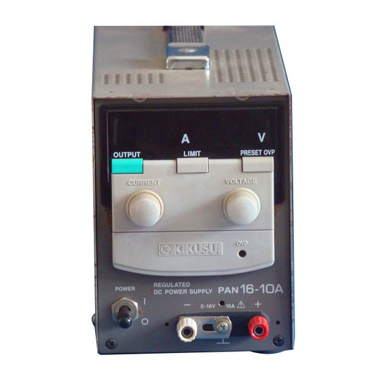
PAN 16-10A
PAN 60-3A
PAN 110-1.5A
350W MODEL
PAN 16-18A
PAN 60-6A
PAN 110-3A
700W MODEL
PAN 16-30A
PAN 60-10A
PAN 110-5A
PAN 250-2.5A
1000W MODEL
PAN 16-50A
PAN 60-20A
PAN 110-10A
PAN 250-4.5A
PAN 600-2A
Part No. Z1-002-322, IA003474
PAN 35-5A
PAN 70-2.5A
PAN 160-1A
PAN 35-10A
PAN 70-5A
PAN 160-2A
PAN 35-20A
PAN 70-8A
PAN 160-3.5A
PAN 35-30A
PAN 70-15A
PAN 160-7A
PAN 350-3.5A
Apr. 2009
Advertisement
Table of Contents

Related Manuals for Kikusui PAN 16-10A


Summary of Contents for Kikusui PAN 16-10A
- Page 1 Part No. Z1-002-322, IA003474 Apr. 2009 OPERATION MANUAL Regulated DC Power Supply PAN-A Series 175W MODEL PAN 16-10A PAN 35-5A PAN 60-3A PAN 70-2.5A PAN 110-1.5A PAN 160-1A 350W MODEL PAN 16-18A PAN 35-10A PAN 60-6A PAN 70-5A PAN 110-3A...
-
Page 2: About This Manual
If you find any incorrectly arranged or missing pages in this manual, they will be replaced. If the manual gets lost or soiled, a new copy can be provided for a fee. In either case, please contact Kikusui agent/distributor, and provide the "Part No." given on cover. - Page 3 Power Requirements of this Product Power requirements of this product have been changed and the relevant sections of the Operation Manual should be revised accordingly. (Revision should be applied to items indicated by a check mark .) Input voltage The input voltage of this product is _______________ VAC, and the voltage range is __________ to ______________ VAC.
- Page 4 PAN-A...
-
Page 5: Safety Symbols
Safety Symbols For the safe use and safe maintenance of this product, the following symbols are used throughout this manual and on the product. Understand the meanings of the symbols and observe the instructions they indicate (the choice of sym- bols used depends on the products). -
Page 6: Safety Precautions
Safety Precautions The following safety precautions must be observed to avoid fire hazard, electrical shock, accidents, and other failures. Keep them in mind and make sure that all of them are observed properly. Using the product in a manner that is not specified in this manual may impair the protection functions provided by the product. - Page 7 Cover • There are parts inside the product which may cause physical hazards. Do not remove the external cover. Installation • When installing products be sure to observe "1.3 Precautions for installation" described in this manual. • To avoid electrical shock, connect the protective ground terminal to electrical ground (safety ground).
- Page 8 • To maintain performance and safe operation of the product, it is recommended that periodic maintenance, checking, cleaning, and calibration be performed. Service • Internal service is to be done by Kikusui service engineers. If the product must be adjusted or repaired, contact Kikusui distributor/agent. PAN-A...
-
Page 9: Arrangement Of This Manual
Arrangement of this manual This Operation Manual is made up of the following sections. Preface Describes all the models covered by this manual, as well as out- lines the features of each model. Chapter 1 "Setup" This chapter describes the necessary procedure from unpacking to preparation before use. - Page 10 Chapter 7 "Specifications" Describes the electrical, mechanical and general specifications of the unit. VIII PAN-A...
-
Page 11: Table Of Contents
CONTENTS Safety Symbols- - - - - - - - - - - - - - - - - - - - - - - - - - - - - - - - - - - - - III Safety Precautions - - - - - - - - - - - - - - - - - - - - - - - - - - - - - - - - - - IV Arrangement of this manual - - - - - - - - - - - - - - - - - - - - - - - - - - VII Preface - - - - - - - - - - - - - - - - - - - - - - - - - - - - - - - - - - - - - - - - - P-1... - Page 12 Chapter 4 Applied Operation - - - - - - - - - - - - - - - - - - - - - - - - - 4-1 CONTROL terminal board - - - - - - - - - - - - - - - - - - - - - - - - - - - - - -4-1 Remote sensing - - - - - - - - - - - - - - - - - - - - - - - - - - - - - - - - - - - - -4-5 Analog remote control - - - - - - - - - - - - - - - - - - - - - - - - - - - - - - - - 4-10 4.3.1...
-
Page 13: Preface
Preface Outline of the manual The PAN-A series is classified depending on output capacity. This Operation Manual describes the PAN-A series, including the specific types named below. PAN-A SERIES MODEL 175W PAN16-10A, PAN35-5A, PAN60-3A, PAN70-2.5A, PAN110-1.5A, PAN160-1A PAN-A SERIES MODEL 350W PAN16-18A, PAN35-10A, PAN60-6A, PAN70-5A, POWER... -
Page 14: Introduction Of The Products
• The remote control and remote sensing terminals use screwless ter- minal boards, which facilitates wiring. • Using the Kikusui power supply controller with the control board allows you to construct an automatic tester and other systems. • The PAN-A series uses a choke input smoothing circuit in the phase control pre-regulator;... - Page 15 For rack mounts, therefore, we request that you mount a blank panel of at least one panel wide on the rack. For details on optional accessories, contact your Kikusui agent. *1. One panel wide; JIS standard: 50 mm, EIA standard: 44.45 PAN-A...
- Page 16 MODEL 175W Rack mount frame RMF4 Blank panel BP2 Blank panel BP4 Bracket B42 Unit: mm (inch) Rack mount frame RMF4M Blank panel BP2 Blank panel BP4 Bracket B42 Unit: mm Fig.P-2 Model 175W mounted into RMF4M/RMF4 PAN-A...
- Page 17 MODEL 350W/700W Rack mount frame RMF4 Blank panel BP2 Bracket B22 Unit: mm (inch) Rack mount frame RMF4M Blank panel BP2 Bracket B22 Unit: mm Fig.P-3 Model 350W/700W mounted into RMF4M/ RMF4 PAN-A...
- Page 18 MODEL 1000W Bracket BH4 Unit: mm (inch) Bracket BH4M Unit: mm Fig.P-4 Model 1000W with BH4M/ BH4 mounted on it PAN-A...
-
Page 19: Chapter 1 Setup
When you unpack the product, make sure that you have all the parts and that none have been damaged during transportation. If any parts is damaged or missing, contact your Kikusui agent/distributor. Accessories vary depending on the model. MODEL 175W Operation manual Guard cap 2 pcs. - Page 20 MODEL 350W Guard cap 2 pcs. Auxiliary output terminal Operation manual GP01-PMC cover [Z1-002-322] [83130] Cover:[P1-000-047] Screw:[M3-112-019] Rear output terminal cover Fuse (Mount on the unit. ) [99-00-0112] [Q5-000-170] Plug: CEE7/7 Plug: CB1002 Plug: NEMA5-15 [85-AA-0005] [85-10-0790] [85-AA-0006] AC power cable The power cord that is provided varies depending on the destination for the product at the factory-shipment.
- Page 21 MODEL 700W Guard cap 2pcs. Operation manual Auxiliary output GP01-PMC [Z1-002-322] terminal cover [83130] Cover:[P1-000-047] Screw:[M3-112-019] Rear output terminal cover Fuse (Mount on the unit. ) [99-00-1409] [Q5-000-170] (PAN35-20A:[99-00-0437]) Accompanying screwA:[M8-600-013] Cable clamp:[P1-750-001] Fastening plate:[D6-750-001] Accompanying screwB:[M3-112-017] PAN35-20A (with no plug) Cable:[85-10-0630] Accompanying screwA:[M8-600-013] PAN16-30A...
- Page 22 MODEL 1000W Operation manual Guard cap 2 pcs. Auxiliary output terminal cover [Z1-002-322] GP01-PMC (Not included for the PAN16-50A.) [83130] Cover:[P1-000-047] Screw:[M3-112-019] PAN35-30A [Q5-000-170] PAN60-20A PAN70-15A PAN110-10A PAN16-50A PAN160-7A PAN250-4.5A PAN350-3.5A Rear output terminal cover PAN600-2A (Mount on the unit.) Accompanying screwA:[M8-600-013] Cable clamp:[P1-750-001] Fastening plate:[D6-750-001]...
-
Page 23: Precautions For Moving
Precautions for moving To carry the unit, hold the handle as shown below. When moving the unit for a short distance, to the next room, for example, carry it on a wagon whenever available. • For safety, check that the power switch is turned off. WARNING •... - Page 24 MODEL 700W In the case of the model 700W, the power transformer is located on the left seen from the front, and the center of gravity of the unit is deviated to the left. For carrying the unit, take sufficient care. •...
- Page 25 To carry the unit, hold handles on the front panel and rear panel with two persons or more, or stand the unit as shown in Fig.1-8, and hold handles on the front panel with two persons. After moving, quickly place the unit with its bottom underneath. Remove the cable clamp and AC power cable from the rear panel before moving the unit.
-
Page 26: Precautions For Installation
fire. Modification may allow the unit to cope with such an atmosphere. If the unit is to be used in such an atmosphere, contact your Kikusui agent. ■ Do not locate the unit in a dusty location. -
Page 27: Checking The Input Fuse
■ Do not install the unit along a tilted section of floor or in a location subject to vibrations. If placed on a non-level surface or in a location subject to vibration, the unit may fall, resulting in damage and injury. ■... -
Page 28: Connecting The Ac Power Code
MODEL 175W/1000W The input fuses of the models 175W and 1000W are located inside, and users are not able to check or replace them. • Users are requested to never remove the cover and WARNING check or replace the fuse. Connecting the AC power code Connect the AC power code to an AC power source specified for the unit. - Page 29 MODEL 700W/1000W • To avoid electric shock, first connect the cable to the WARNING AC IN terminal board before connecting it to the power source. • Inside the unit, protective circuits including input CAUTION fuses are connected in order to meet the input termi- nal rating.
- Page 30 Connecting procedure of AC power source side MODEL 175W/350W/700W(Except PAN35-20A) 1. Insert the plug of the AC power code into an outlet. ■ If the supplied AC power code has no plug: Models that have had their rated inputs changed according to a fac- tory option, i.e., those other than 100 V AC input models, may come with no plugs.
- Page 31 PAN35-20A(MODEL 700W)/MODEL 1000W • To prevent electric shock, turn OFF the switch on the WARNING switchboard (to cut off the power feed from the switchboard) and then connect the AC power code. • Inside the unit, protective circuits including input CAUTION fuses are connected in order to meet the input termi- nal rating.
-
Page 32: Grounding
Grounding • Improper or no grounding may cause electrical WARNING shock. • Connect the ground terminal to electrical ground (safety ground). MODEL 175W/350W/700W(Except PAN35-20A) Connect the AC power code to a grounded 3-pin outlet. PAN35-20A(MODEL 700W)/MODEL 1000W In the case of the PAN35-20A and the models 1000W, securely con- nect the (GND) wire of the power cable to the ground terminal on the switchboard. -
Page 33: Chapter 2 Before Using The Unit
Chapter 2 Before Using the Unit Before using the unit, users are requested to thoroughly understand the following matters. Inrush current An inrush current may flow when the POWER switch is turned on. See Table 2-1. If you are planning to use several sets of the unit in a system, and to turn on the POWER switches at the same time, check that the AC power source or the switchboard is of sufficient capacity. -
Page 34: Output Terminals On The Front Panel
Output terminals on the front panel The output terminals on the front panel are auxiliary output terminals. These terminals, however, may not satisfy the given specifications of the unit. The PAN16-50A has no output terminals on the front panel. Load Note that the output may become unstable when one of the following loads is connected. -
Page 35: When A Load Generates A Reverse Current To The Power Supply
2.4.2 When a load generates a reverse current to the power supply The unit cannot absorb a reverse current from a regenerative load such as an inverter, converter or transformer that supplies current to a power supply. Consequently, the output voltage will increase and the output will fluctuate. -
Page 36: In Case Of Load With Accumulated Energy, Such As Batteries
2.4.3 In case of load with accumulated energy, such as batteries Connecting a load with accumulated energy, such as a battery, to the output of the unit may cause a large current to flow from the load through the internal output control circuit protection diode to the internal capacitor. -
Page 37: Cv Power Supply And Cc Power Supply
CV power supply and CC power supply The unit is capable of both constant voltage and constant current operation. This section describes these operations. The ideal constant voltage power supply has zero output impedance at all frequencies and maintains a definite constant output voltage with respect to variations in load current. - Page 38 ■ Connecting a 10 Ω resistive load A resistive load of 10 Ω is connected to the output terminals of the power supply and the output current limit is set to 5 A. In this condi- tion, output voltage is raised gradually from 0 V. In this case, the power supply operates in the constant voltage (CV) mode.
- Page 39 ■ Connecting a 25 Ω resistive load We consider a case of using a load resistance of 25 Ω. In this case, when the output current limit is set to 4 A or more, the power supply is capable of outputting voltages from 0 V to the rated maximum out- put voltage while in constant voltage operation mode.
-
Page 40: Output Terminal Isolation
Output Terminal Isolation • Be sure to securely connect the output terminal to WARNING the chassis terminal using the short bar provided. Possible electric shock may lead to death or injury. • For safety reasons, even if the output terminal is CAUTION grounded, make sure the insulation capacity of the output terminal (including the sensing terminal) is... - Page 41 ■ When the output terminal is not grounded The cable and load that are connected to the output terminal (includ- ing the sensor terminal) must have an insulation capacity that is greater than the isolation voltage of the power supply with respect to the chassis.
- Page 42 ■ When the negative output terminal is connected to the chassis terminal As shown in Fig.2-9, the negative output terminal will be at ground potential. Consequently, the cable and load that are connected to the output terminal (including the sensor terminal) must have an insula- tion capacity that is greater than the maximum output voltage of the power supply with respect to the chassis.
- Page 43 Control terminal Rext Approx. the same potential as the positive output terminal – – Vext PAN-A Output terminal AC input terminal Load –S – – Since the negative output terminal is at ground potential, the section indicated in gray must have an insulation capacity that is greater than the maximum output Short bar voltage of the power supply with respect...
- Page 44 2-12 PAN-A...
-
Page 45: Chapter 3 Basic Operation
Chapter 3 Basic Operation This chapter describes the basic operations that you can perform from the front panel. Turning on the power Before turning on the POWER switch, always check the status of the OUTPUT switch. Push in the OUTPUT switch to turn it on, and release it to turn it off. - Page 46 Turning on the power procedure 1. Check that the POWER switch is turned off. 2. Check that the OUTPUT switch is turned off. 3. Open the front sub-panel cover of the control panel to con- firm that all control switches (S1 to S5) are off. 4.
- Page 47 PRESET OVP PRESET OVP OUTPUT OUTPUT LIMIT LIMIT OUTPUT switch LIMIT CURRENT VOLTAGE switch CURRENT VOLTAGE control control knob knob Control switch Front sub-panel cover Hold the right and left edges of the sub-panel between your fingers and open the front sub-panel cover towards you. Fig.3-1 Control panel PAN-A...
-
Page 48: Basic Operation
Basic operation There are two different modes for the unit: constant voltage (CV) mode, and the constant current (CC) mode. Before starting to use the unit, determine which mode is to be employed, and select the proce- dure suitable for the selected operation mode. •... - Page 49 Presetting the OVP trip point • After presetting the OVP trip point, be sure to check CAUTION that the OVP function works at the preset voltage (Procedure 4 to 6). For checking, it is necessary to output an actual voltage. Therefore, first check that no load is connected, and proceed with the following procedure.
-
Page 50: Using As A Constant Voltage Power Supply
3.2.2 Using as a constant voltage power supply • For safety, turn off the POWER switch when connect- WARNING ing the load. 1. Check that the OUTPUT switch is turned off. 2. Turn on the POWER switch. 3. While pressing the LIMIT switch, preset the requested cur- rent by turning the CURRENT control knob. -
Page 51: Using As A Constant Current Power Supply
3.2.3 Using as a constant current power supply • For safety, turn off the POWER switch when connect- WARNING ing the load. 1. Check that the OUTPUT switch is turned off. 2. Turn on the POWER switch. 3. While pressing the LIMIT switch, preset the requested volt- age by turning the VOLTAGE control knob. -
Page 52: Connecting Load
+ (pos.) and - (neg.) output lines side by side or bundling them together is more effective against unneces- sary noise. The Kikusui-recommended currents shown in Table 3-1 are allowable current values that have been reduced in consideration of potential bundling of load cables. - Page 53 Table 3-1 Nominal Cross-sectional Areas of Cables and Allowable Currents Nominal (Reference Allowable Current cross-sectional cross-sectional recommended current area [mm area) [mm by Kikusui [A] (Ta = 30 ˚C) (0.82) 1.25 (1.31) (2.08) (3.31) (5.26) (8.37) (13.3) (21.15) (33.62) (42.41) (53.49)
- Page 54 Using the auxiliary output terminals on the front panel • For safety, turn off the POWER switch when connect- WARNING ing the load. • After connecting the load cable, mount the auxiliary output terminal cover. To mount the auxiliary output terminal cover, see "3.4 Mounting the auxiliary output terminal cover".
- Page 55 Using the OUTPUT terminal board on the rear panel • For safety, turn off the POWER switch when connect- WARNING ing the load. • After connecting the load cable, mount the rear out- put terminal cover. CAUTION • To assure a good connection of the load cable to the output terminals, use crimped terminals.
- Page 56 MODEL 350W/700W/1000W Crimped terminal on the load cable OUTPUT OUTPUT terminal terminal board board When the terminal board is not used, fix the terminal cover using the upper hole. Fig.3-4 Connection to the OUTPUT terminal board on the rear panel (model 350W/700W/1000W) As shown in Fig.3-4, lay load cables at the right of the OUTPUT ter- minal board, as seen from the rear panel.
-
Page 57: Mounting The Auxiliary Output Terminal Cover
Mounting the auxiliary output terminal cover The unit is provided with a front auxiliary output terminal cover. Mount the cover when the unit is to be used. The PAN16-50A has no auxiliary output terminals on the front panel. • The output electrode on the auxiliary output terminal WARNING is uncovered. -
Page 58: Fixing Output Presetting
Fixing output presetting The unit includes VOLTAGE and CURRENT control knobs; in order to make them mechanically fixed or semi-fixed, guard caps are sup- plied with the unit. Use them if output presetting is seldom necessary. Using the guard caps 1. - Page 59 To fix Pierce this surface with a Phillips-head screwdriver. To semi-fix Work on a firm stand. Fig.3-6 Mounting the guard cap Metal Fig.3-7 Metal Fitting inside the Bushing PAN-A 3-15...
- Page 60 Re-mounting the control knob There is a slot on the end of the shaft of the output preset variable resistor. Mount the knob so that it engages the slot to prevent the knob from turning freely. Follow the procedure described below. 1.
-
Page 61: Chapter 4 Applied Operation
Chapter 4 Applied Operation Use of the CONTROL terminal board on the rear panel allows the unit to perform remote sensing, external output control, parallel oper- ation, and series operation. • To avoid electric shock, for remote sensing lines and WARNING control lines, use wires with a rated voltage higher than the isolation voltage of the unit. - Page 62 Table 4-1 Alignment on CONTROL terminal board Expres- Signal Description Expression on the sion on the name CAUTION label No. panel No connection 19 NC • No connection 18 NC MASTER Master unit output for master-slave con- • 17 MASTER OUT trol parallel connection MASTER Master unit common line for master-...
- Page 63 PAN350-3.5A/ PAN600-2A (1000W model) Group A Group A Group B Group B Applicable wires Group A (No. 2 to 19 terminals) φ0.32 to φ0.65 (AWG28 to AWG22) Single wire: Twisted wire: 0.08 mm to 0.32 mm (AWG28 to AWG22) Group B (-S, +S, and No. 1 terminals) φ0.4 to φ1.2 (AWG26 to AWG16) Single wire: Twisted wire: 0.3 mm...
- Page 64 3. Use a wire stripper to remove the covering from wires. Remove the covering from each wire over a distance of 7 mm to 10 mm (9 mm is recommended). Use of the strip gauge on the top or rear panel of the unit, or that shown in Fig.4-2, allows you to remove the required amount of covering from a wire.
-
Page 65: Remote Sensing
Remote sensing The remote sensing function is intended to reduce the influence of voltage drops affected by the load cable resistance, to keep the output voltage stable at the load terminal. To perform remote sensing, an electrolytic capacitor that has good frequency characteristics is needed at the sensing point (load terminal). - Page 66 • For sensing wires, use wires with a higher voltage WARNING rating than the isolation voltage of the unit. For details, see "2.6 Output Terminal Isolation". Protect the uncovered section of the shielded wire by using insulation tubes with a withstand voltage greater than the isolation voltage of the unit.
- Page 67 CONTROL terminal board − S Turn on SENS the switch. Load Crimped terminal 2-core shielded wire OUTPUT terminal board Fig.4-5 Remote sensing connection (PAN16-50A) CONTROL terminal board − S Turn on SENS the switch. Crimped terminal Load 2-core shielded wire OUTPUT terminal board Fig.4-6...
- Page 68 Load − − S Fig.4-7 Power ON/OFF using mechanical switches 4. Connect an electrolytic capacitor (C) with a capacity of a few thousands of μF to a few tens of thousands of μF across the load terminals. • Use a capacitor (C) whose withstand voltage is 120 CAUTION % or more of the unit's rated voltage.
- Page 69 6. Turn on the sensing switch. To turn the sensing switch (SENS) ON/OFF, push the switch to the inside than the panel surface with a not sharp pointed stick such as a flat-blade screwdriver. Fig.4-8 Changing the sensing switch (SENS) •...
-
Page 70: Analog Remote Control
Analog remote control It is possible to remotely control the unit's output voltage and current using analog signals. Output ON/OFF operation by means of external contact points is also possible. The above-mentioned remote of controls can be used in combination, but note the following exceptions. - Page 71 ■ Before performing analog remote control The unit is factory-adjusted for control from the front panel (i.e., local control). Before using remote control (excluding output ON/OFF using external contact points), re-adjustment is necessary. Re-adjust- ment is also necessary when changing from remote control back to local control.
-
Page 72: Controlling Output Voltage With External Resistor
4.3.1 Controlling output voltage with external resis- This method is used to control output voltage using a 0 Ω to approx. 10 kΩ external resistor. • The insulation of the external resistance (Rext) and WARNING the cable connecting to it should be greater than the isolation voltage of the unit. - Page 73 NOTE • To minimize the influence of noise on the output, use a 2-core shielded wire or a twisted-pair wire to connect the control ter- minals and Rext. If using a shielded wire, connect the shield to the + (pos.) output terminal. Note that longer lengths of wiring result in more susceptibil- ity to the effects of noise;...
-
Page 74: Controlling Output Voltage With External Voltage
4.3.2 Controlling output voltage with external voltage This method is used to control output voltage using 0 V to approx. 10 • The insulation of the external voltage source (Vext) WARNING and the cable connecting to it should be greater than the isolation voltage of the unit. - Page 75 output voltage. If output preset on the panel needs to be fixed, use the supplied guard cap. 4. Set the control switches S1 and S2 to the position shown in Fig.4-11. 5. Connect the voltage source across the control terminals [2] and [3] as shown in Fig.4-11.
- Page 76 Rear CONTROL Front control panel terminal board Set S1 to the upper position and S2 to the lower position. α Ertg • Vext • Output voltage Eo ≈ Vext:external voltage source 0 ≤ Vext ≤ 10.5[V] 2-core shielded wire or Ertg: rated output voltage [V] twisted-pair wire α: Coefficient 0 to 1 determined by the...
- Page 77 ■ When you wish to connect the shield to Vext • If you are connecting the shield to the Vext side when CAUTION using external voltage control, do not connect the shield to the + (pos.) output terminal of the unit. When using shielded wires, some external voltage sources may require that the shield be connected to the external voltage source.
-
Page 78: Controlling Output Current With External Resistor
4.3.3 Controlling output current with external resis- This method is used to control output current using a 0 Ω to approx. 10 kΩ external resistor. • The insulation of the external resistance (Rext) and WARNING the cable connecting to it should be greater than the isolation voltage of the unit. - Page 79 NOTE • To minimize the influence of noise on the output, use a 2-core shielded wire or a twisted-pair wire to connect the control ter- minals and Rext. If using a shielded wire, connect the shield to the + (pos.) output terminal. Note that longer lengths of wiring result in more susceptibil- ity to the effects of noise;...
-
Page 80: Controlling Output Current With External Voltage
4.3.4 Controlling output current with external voltage This method is used to control output current using 0 V to approx. 10 V external voltage. • The insulation of the external voltage source (Vext) WARNING and the cable connecting it should be greater than the isolation voltage of the unit. - Page 81 NOTE • For output current control with an external voltage, you can use the current CURRENT control knob to adjust the ratio of the output current to the input voltage from the external volt- age source (Vext). (See Fig.4-14.) Therefore, keep the control knob turned fully clockwise so that output current can be remotely controlled, up to the rated output current.
- Page 82 Rear CONTROL Front control panel terminal board Set S3 to the upper position and S4 to the lower position. Irtg • Vext • β Output current Io ≈ 2-core shielded wire or twisted-pair wire Vext: external voltage source 0 ≤ Vext ≤ 10.5 [V] Irtg: rated output current [A] Vext Rear OUTPUT...
- Page 83 ■ When you wish to connect the shield to Vext • When connecting the shield to the Vext side, do not CAUTION connect the shield to the + (pos.) output terminal of the unit. When using shielded wires, some external voltage sources may require that the shield be connected to the external voltage source.
-
Page 84: Output On/Off Control
4.3.5 Output ON/OFF control This method is used to control the output's ON/OFF status using external contact points. Output is turned off when the external contact points are closed. • The insulation of the external contact (S) and the WARNING cable connecting it should be greater than the isola- tion voltage of the unit. - Page 85 NOTE • To minimize the influence of noise on the output, use a 2-core shielded wire or a twisted-pair wire to connect the control ter- minals and the external contact points. If using a shielded wire, connect the shield to the + (pos.) output terminal. Note that longer lengths of wiring result in more susceptibil- ity to the effects of noise;...
-
Page 86: Master-Slave-Control Parallel Operation
Master-slave-control parallel operation It is possible to increase the current capacity by connecting a maxi- mum two slave units in parallel to one master unit. In a master-slave- control parallel operation system, the output preset for all the units connected in parallel can be provided only on the master unit. To perform such master-slave-control parallel operation, an electro- lytic capacitor should be connected to the load terminals. -
Page 87: Connection And Setup Procedure
Connection and setup procedure 1. Turn off the OUTPUT switch of each unit. 2. Turn off the POWER switch of each unit. 3. Determine the master unit. NOTE • If the PAN-A and PAN series are used together, assign the PAN-A series power supply as the master unit. - Page 88 • Use a load cable of sufficient current capacity to WARNING cover the rated value. • After parallel connection, mount the output terminal cover (on the front or rear panel). To mount the front auxiliary output terminal cover, see "3.4 Mounting the auxiliary output terminal cover".
- Page 89 7. Connect an electrolytic capacitor (C) with a capacity of a few hundreds of μF to a few tens of thousands of μF to the load terminals as necessary. • Use a capacitor (C) whose withstand voltage is 120 CAUTION % or more of the unit's rated voltage.
- Page 90 Remove Remove Connect the shorting bar to the shorting bar. the shorting bar. the - (neg.) or + (pos.) terminal. Master unit Slave unit 1 Slave unit 2 Front panel auxiliary Front panel auxiliary Front panel auxiliary output terminals output terminals output terminals Load Master unit...
- Page 91 Connect the shorting bar to Remove Remove the - (neg.) or + (pos.) terminal. the shorting bar. the shorting bar. Load Master unit Slave unit 1 Slave unit 2 L1 = L2 = L3 Rear OUTPUT Rear OUTPUT Rear OUTPUT terminal board terminal board terminal board...
- Page 92 Remove Remove Connect the shorting bar to the shorting bar. the shorting bar. the - (neg.) or + (pos.) terminal. Master unit Slave unit 1 Slave unit 2 Front panel auxiliary Front panel auxiliary Front panel auxiliary output terminals output terminals output terminals Load Master unit...
- Page 93 Starting master-slave-control parallel operation • To start master-slave-control parallel operation, CAUTION always follow the procedure below. Because the slave units are under control of the master unit, if the procedure is incorrectly observed, the slave units may output their maximum output voltage. 1.
- Page 94 7. Turn on the OUTPUT switch of the master unit. "CV" lights up on the master unit control panel, indicating that the unit is in constant voltage operation mode. The same output voltage and current displayed on the master unit are also displayed on all the slave units.
-
Page 95: Master-Slave-Control Series Operation
Master-slave-control series operation It is possible to increase the output voltage by connecting several slave units in series to one master unit. In a master-slave-control series operation system, a preset output for all the units connected in series can be designated only from the master unit. •... - Page 96 • Be sure to observe the limitation on the maximum WARNING number of units that can be connected in series. If the maximum output voltage exceeds the isolation voltage, it may create a danger of electric shock. • Series connection is possible only for the PAN-A or CAUTION PAN series power supplies that have the same rated output voltage and rated output current.
- Page 97 ■ Presetting of OVP trip points in series operation When carrying out series operation, OVP (overvoltage protection) trip points should be preset for both the master unit and for all slave units. In series operation, the OVP trip points for slave units should be set to slightly higher values than that used for the master unit.
- Page 98 6. Connect the master unit and slave units shown in Fig.4-22. Fig.4-22 shows an example of how the rear output terminals are connected in series for two slave units. For the PAN16-50A user, see Fig. Fig.4-24. When performing remote sensing in master-slave-control series operation, see Fig.4-23.
- Page 99 Connect any one of the + and - terminals to the chassis ground terminal, using a shorting bar. Master unit Slave unit 1 Slave unit 2 Front panel auxiliary Front panel auxiliary Front panel auxiliary output terminals output terminals output terminals Load Select the shortest and Select the shortest and...
- Page 100 Connect any one of the + and - terminals to the chassis ground terminal, using a shorting bar. Master unit Slave unit 1 Slave unit 2 Front panel auxiliary Front panel auxiliary Front panel auxiliary output terminals output terminals output terminals Select the shortest and heaviest gauge wires practical for this wiring...
- Page 101 Connect any one of the + and - terminals to the chassis ground terminal, using a shorting bar. Select the shortest Select the shortest and heaviest gauge and heaviest gauge wires practical for wires practical for this wiring this wiring Load Master unit Slave unit 1...
- Page 102 Connect any one of the + and - terminals to the chassis ground terminal, using a shorting bar. Master unit Slave unit 1 Slave unit 2 Front panel auxiliary Front panel auxiliary Front panel auxiliary output terminals output terminals output terminals Load Select the shortest and Select the shortest and...
- Page 103 Connect any one of the + and - terminals to the chassis ground terminal, using a shorting bar. Master unit Slave unit 1 Slave unit 2 Front panel auxiliary Front panel auxiliary Front panel auxiliary output terminals output terminals output terminals Select the shortest and heaviest gauge wires practical for this wiring Load...
- Page 104 NOTE • Assign the PAN-A series as the master unit. • Slave units may be either PAN-A series or PAN series. • For external resistor (Rext), use a 1 W or larger metal film or wire-wound type resistor with a good temperature coefficient and small aging effect.
- Page 105 7. Turn on the OUTPUT switch of the master unit. "CV" lights up on the control panel of the master unit, indicating that the unit is in constant voltage operation mode. The same output voltage and current displayed on the master unit are also displayed on each slave unit.
- Page 106 4-46 PAN-A...
-
Page 107: Chapter 5 Names And Functions Of Controls
Chapter 5 Names and Functions of Controls Front panel Control panel [4] [3] Fig.5-1 Front panel of PAN-A series model 175W Control panel POWER [4] [3] Fig.5-2 Front panel of PAN-A series model 350W PAN-A... - Page 108 Control panel Fig.5-3 Front panel of PAN-A series model 700W Control panel [4] [3] Fig.5-4 Front panel of PAN-A series model 1000W NOTE • On the front panel of the PAN16-50A, there is no [2] + and - (auxiliary output terminals), [3] ⊥ (chassis ground terminal), and [4] shorting bar for grounding chassis.
- Page 109 [1] POWER Turns the power of the unit on and off. Flip up the lever to turn the power ON (⏐), and flip it down to turn the power OFF ( [2] +, - (auxiliary output terminals) These terminals are designed for handy use in supplying output from the unit.
-
Page 110: Control Panel
Control Panel [12] [16] [13] [14] [15] OUTPUT UTPUT LIMI PRESE SET OV T OVP CURRENT VOLTAGE [10] [17] [11] Fig.5-5 PAN-A series control panel [5] OUTPUT Turns the output on and off. It is turned on at pushed. When the output is turned off, the output circuit is set into a state of high impedance (several kΩ). - Page 111 [10] VOLTAGE This is used to set output voltage for constant voltage operation mode. (10 turns) [11] OVP This is the OVP (overvoltage protection) control variable resistor, and used to preset the trip point of the OVP circuit. [12] Ammeter Indicates the output current when the OUTPUT switch is turned on.
- Page 112 [16] CV "CV" (Constant Voltage) LED is displayed when the unit is in its con- stant voltage operation mode. [17] Front sub-panel cover This is used to cover the switches and variable resistors that are sel- dom used. To open it, press both sides of the cover and pull it for- ward.
-
Page 113: Rear Panel
Rear panel CONTROL [21] [20] OUTPUT SENS [23] [18] AC IN [24] [22] Fig.5-6 Rear panel of PAN-A series model 175W CONTROL [19] [21] OUTPUT AC IN SENS [23] [18] [22] [24] [20] Fig.5-7 Rear panel of PAN-A series model 350W PAN-A... - Page 114 CONTROL [19] [21] OUTPUT AC IN SENS [18] [23] [22] [24] [20] Fig.5-8 Rear panel of PAN-A series model 700W CONTROL CONTROL TERMINAL DO NOT REMOVE COVERS, REFER SERVICING TO QUALIFIED PERSONNEL. SECURELY DISCONNECT INPUT POWER CABLE FROM AC OUTLET OR SWITCH- MASTER OUT BOARD BEFORE HANDLING INPUT MASTER COM...
- Page 115 [18] AC IN AC input terminals. Connect the supplied AC power code. • Incorrect handling may cause electric shock. Always WARNING follow the instructions in section "1.5 Connecting the AC power code". • Make sure that the ground terminal is securely grounded.
- Page 116 [22]OUTPUT This is the output terminal board. • To avoid electric shock, always turn off the POWER WARNING switch whenever it is necessary to touch the termi- nals. [23] SENS Turn this switch on when using the sensing function. It is turned on at pushed.
-
Page 117: Chapter 6 Maintenance
Check that there is no damage on the insulation coating, and that the plug is firmly attached and free from cracks. • Breaks in the insulation coating may cause electric WARNING shock. If a break is found, immediately stop using the unit. To purchase accessories, contact your Kikusui agent/distributor. PAN-A... -
Page 118: Adjustment
• Never touch the variable resistors "1", "3", "9" and "10", as they are not involved in the user adjustment process. If you have moved any of them by mistake, re-adjustment is neces- sary. In such cases, contact your Kikusui agent/distributor. PAN-A... - Page 119 Voltage system adjustment procedure The voltage system includes the following three items. Since all the items are related to one another, adjust them all in the following pro- cedure. • Output voltage offset • Output voltage in full scale • Output voltage display in full scale ■...
- Page 120 Crimped Connect the shorting bar terminal to the - (neg.) terminal. Rear OUTPUT terminal board Fig.6-2 Connection for voltage system adjustment (PAN16-50A) 6. Turn on the POWER switch. ■ Warming-up NOTE • To minimize adjustment error affected by initial drift, warm up the unit at least 30 minutes before starting adjustment.
- Page 121 13. Using variable resistor "2", adjust the output voltage to 0 V. Output voltage in full scale 14. Set the output voltage to the maximum. For local control, turn the VOLTAGE control knob fully clock- wise. For remote control, set the control signal to 10.5 V or 10 kΩ.
- Page 122 Current system adjustment procedure The current system includes the following three items. Since all the items are related to one another, adjust them all in the following pro- cedure. • Output current offset • Output current in full scale • Output current display in full scale ■...
- Page 123 Crimped Connect the shorting terminal bar to the - (neg.) terminal. Shunt resistor Rear OUTPUT terminal board Fig.6-5 Connection for current system adjustment (PAN16-50A) 6. Turn on the POWER switch. ■ Warming-up NOTE • To minimize adjustment error affected by initial drift, warm up the unit at least 30 minutes before starting adjustment.
- Page 124 Output current in full scale 14. Set the output current to the rated output current. For local control, turn the CURRENT control knob fully clock- wise. For remote control, set the control signal to 10.5 V or 10 kΩ. 15. Using variable resistor "7", adjust the output current to 105 % of the rated output current.
-
Page 125: Malfunctions And Causes
When you find a relevant item, follow the corresponding remedy. If this does not solve or improve the problem, or if no relevant item can be located, please contact your Kikusui agent/distributor. ■ Symptom 1: The control panel displays nothing. - Page 126 ■ Symptom 2: When you turn on the POWER switch, it is turned off or the "ALM" LED lights up. Check item Cause and remedy The overcurrent protection circuit has • Check that switch S4 on the control panel has not been activated.
- Page 127 ■ Symptom 3: When you turn on the OUTPUT switch, the POWER switch is turned off or the "ALM" LED lights up. Check item Cause and remedy • The overvoltage protection circuit has been Check that the OVP trip activated. Preset the OVP trip point to a level point is not preset to a above the output voltage.
- Page 128 ■ Symptom 4: No output is generated even when the OUT- PUT switch is turned on. Check item Cause and remedy • The VOLTAGE and CURRENT control Check to see if both the knobs have been turned fully counterclock- "CV" and "CC" LEDs are wise.
- Page 129 ■ Symptom 5: No output is generated or the output is unsta- ble even when the OUTPUT switch is turned on. Check item Cause and remedy • Turn the control knob (VOLTAGE or CURRENT) Check to see if the that has been clamped, in the clockwise direction. If operation mode the knob has already been turned fully clockwise, it is changes from CV...
- Page 130 Check that the load cur- rent has peaks or is pulse- shaped. • Internal reference voltage has been Check that the variable changed. Because re-adjustment is neces- resister '1' on the control sary, contact your Kikusui agent/distributor. panel was moved. 6-14 PAN-A...
-
Page 131: Chapter 7 Specifications
Chapter 7 Specifications Unless otherwise specified, the specifications of the unit are based on the following conditions. • The load is a pure resistance. • The - (neg.) output terminal is connected to the ( ⊥ ) chassis ground terminal with the supplied shorting bar. •... -
Page 132: Specifications Of Pan-A Series Model 175W
Specifications of PAN-A Series Model 175W Model 175W PAN16-10A PAN35-5A PAN60-3A Input Power consumption, at 100 VAC, Approx.400 VA Approx.400 VA Approx.350 VA rated load Output Voltage Rated voltage 16 V 35 V 60 V Variable range 0 V to 16V 0 V to 35V 0 V to 60V Resolution (theoret-... - Page 133 PAN70-2.5A PAN110-1.5A PAN160-1A Approx.350 VA Approx.400 VA Approx.330 VA 70 V 110 V 160 V 0 V to 70 V 0 V to 110 V 0 V to 160 V 13 mV 20 mV 30 mV 10 turns 2.5 A 1.5 A 0 A to 2.5 A 0 A to 1.5 A...
- Page 134 Model 175W PAN16-10A PAN35-5A PAN60-3A Constant current characteristics Ripple and noise 2 mA 1 mA 1 mA (5 Hz to 1 M Hz) RMS Source effect (to ±10 % of AC 1 mA input voltage) Load effect (to approx. 1 V to 3 mA 2 mA 2 mA...
- Page 135 PAN70-2.5A PAN110-1.5A PAN160-1A 1 mA 1 mA 1 mA 300 ppm/˚C (TYP value) ±250 V ±500 V ±500 V 500 VDC, 30 MΩ min. (measured at ambient humidity 70 % RH max.) 500VDC, 20 MΩ min. (measured at ambient humidity 70 % RH max.) 199.9 ±(0.5 % of rdg +2 digits) at 23 ˚C±5 ˚C...
- Page 136 Model 175W PAN16-10A PAN35-5A PAN60-3A Master-slave-control series operation Possible Protective circuit Over-voltage protection (OVP) Preset range: Approx. 10 % to 110 % of rated for output output voltage ALM LED lights up, control transistor cut off and rectification circuit shut down when OVP tripped. Input fuse 7 A, 125 VAC/250 VAC 6.4 mm dia.x32 mm...
- Page 137 PAN70-2.5A PAN110-1.5A PAN160-1A Possible Preset range: Approx. 10 % to 110 % of rated output voltage ALM LED lights up, control transistor cut off and rectification circuit shut down when OVP tripped. 7 A, 125 VAC/250 VAC Incorporated in transformer Approx.11 kg (24.3 lb) See outline drawing.
-
Page 138: Specifications Of Pan-A Series Model 350W
Specifications of PAN-A Series Model 350W Model 350W PAN16-18A PAN35-10A PAN60-6A Input Power consumption, at 100 VAC, Approx.800 VA Approx.800 VA Approx.700 VA rated load Output Voltage Rated voltage 16 V 35 V 60 V Variable range 0 V to 16V 0 V to 35V 0 V to 60V Resolution (theoret-... - Page 139 PAN70-5A PAN110-3A PAN160-2A Approx.800 VA Approx.700 VA Approx.700 VA 70 V 110 V 160 V 0 V to 70 V 0 V to 110 V 0 V to 160 V 13 mV 20 mV 30 mV 10 turns 0 A to 5 A 0 A to 3 A 0 A to 2 A 0.9 mA...
- Page 140 Model 350W PAN16-18A PAN35-10A PAN60-6A Constant current characteristics Ripple and noise 5 mA 2 mA 2 mA (5 Hz to 1 M Hz) RMS Source effect (to ±10 % of AC 1 mA input voltage) Load effect (to approx. 1 V to 3 mA 100 % of output voltage) Temperature coefficient...
- Page 141 PAN70-5A PAN110-3A PAN160-2A 2 mA 1 mA 1 mA 1 mA 2 mA 300 ppm/˚C (TYP value) ±250 V ±500 V ±500 V 500 VDC, 30 MΩ min. (measured at ambient humidity 70 % RH max.) 500VDC, 20 MΩ min. (measured at ambient humidity 70 % RH max.) 199.9 ±(0.5 % of rdg...
- Page 142 Model 350W PAN16-18A PAN35-10A PAN60-6A Master-slave-control series operation Possible Protective circuit Over-voltage protection (OVP) Preset range: Approx. 10 % to 110 % of rated for output output voltage ALM LED lights up, control transistor cut off and rectification circuit shut down when OVP tripped. Input fuse 10 A, 125 VAC/250 VAC 6.4 mm dia.x32 mm...
- Page 143 PAN70-5A PAN110-3A PAN160-2A Possible Preset range: Approx. 10 % to 110 % of rated output voltage ALM LED lights up, control transistor cut off and rectification circuit shut down when OVP tripped. 10 A, 125 VAC/250 VAC Incorporated in transformer Approx.17 kg (37.5 lb) See outline drawing.
-
Page 144: Specifications Of Pan-A Series Model 700W
Specifications of PAN-A Series Model 700W Model 700W PAN16-30A PAN35-20A PAN60-10A Input Power consumption, at 100 VAC, Approx. Approx. Approx. rated load 1100 VA 1400 VA 1100 VA Output Voltage Rated voltage 16 V 35 V 60 V Variable range 0 V to 16V 0 V to 35V 0 V to 60V... - Page 145 PAN70-8A PAN110-5A PAN160-3.5A PAN250-2.5A Approx. Approx. Approx. Approx. 1100 VA 1000 VA 1000 VA 1100 VA 70 V 110 V 160 V 250 V 0 V to 70 V 0 V to 110 V 0 V to 160 V 0 V to 250 V 13 mV 20 mV 30 mV...
- Page 146 Model 700W PAN16-30A PAN35-20A PAN60-10A Constant current characteristics Ripple and noise 5 mA 3 mA 3 mA (5 Hz to 1 M Hz) RMS Source effect (to ±10 % of AC 3 mA input voltage) Load effect (to approx. 1 V to 3 mA 100 % of output voltage) Temperature coefficient...
- Page 147 PAN70-8A PAN110-5A PAN160-3.5A PAN250-2.5A 2 mA 1 mA 1 mA 2 mA 1 mA 2 mA 2 mA 2 mA 1 mA 300 ppm/˚C (TYP value) ±250 V ±500 V ±500 V ±500 V 500 VDC, 30 MΩ min. (measured at ambient humidity 70 % RH max.) 500VDC, 20 MΩ...
- Page 148 Model 700W PAN16-30A PAN35-20A PAN60-10A Master-slave-control series operation Possible Protective circuit Over-voltage protection (OVP) Preset range: Approx. 10 % to 110 % of rated for output output voltage ALM LED lights up, control transistor cut off and rectification circuit shut down when OVP tripped. Input fuse 15 A, 125 VAC/ 20 A, 125 VAC/...
- Page 149 PAN70-8A PAN110-5A PAN160-3.5A PAN250-2.5A Possible Preset range: Approx. 10 % to 110 % of rated output voltage ALM LED lights up, control transistor cut off and rectification cir- cuit shut down when OVP tripped. 15 A, 125 VAC/250 VAC 10 A Incorporated in transformer Approx.22 kg Approx.22 kg...
-
Page 150: Specifications Of Pan-A Series Model 1000W
Specifications of PAN-A Series Model 1000W Model 1000W 16-50A 35-30A 60-20A Input Power consumption, at 100 VAC, Approx. Approx. Approx. rated load 1600 VA 1800 VA 2100 VA Output Voltage Rated voltage 16 V 35 V 60 V Variable range 0 V to 16V 0 V to 35V 0 V to 60V... - Page 151 70-15A 110-10A 160-7A 250-4.5A 350-3.5A 600-2A Approx. Approx. Approx. Approx. Approx. Approx. 1900 VA 2000 VA 1900 VA 1800 VA 2100 VA 2000 VA 70 V 110 V 160 V 250 V 350 V 600 V 0 V to 70 V 0 V to 110 V 0 V to 160 V 0 V to 250 V...
- Page 152 Model 1000W 16-50A 35-30A 60-20A Constant current characteristics Ripple and noise 10 mA 5 mA 2 mA (5 Hz to 1 M Hz) RMS Source effect (to ±10 % of AC 3 mA 3 mA 1 mA input voltage) Load effect (to approx. 1 V to 5 mA 5 mA 2 mA...
- Page 153 70-15A 110-10A 160-7A 250-4.5A 350-3.5A 600-2A 5 mA 2 mA 2 mA 2 mA 2 mA 0.5 mA 1 mA 1 mA 1 mA 1 mA 1 mA 0.5 mA 3 mA 3 mA 2 mA 2 mA 2 mA 1 mA 300 ppm/˚C (TYP value) ±250 V...
- Page 154 Model 1000W 16-50A 35-30A 60-20A Master-slave-control series operation Possible Protective circuit Over-voltage protection (OVP) Preset range: Approx. 10 % to 110 % of rated for output output voltage ALM LED lights up, control transistor cut off and rectification circuit shut down when OVP tripped. Input fuse 15 mm dia.x40 mm 30 A, 125 VAC/250 VAC Output fuse standard pre-arcing...
- Page 155 70-15A 110-10A 160-7A 250-4.5A 350-3.5A 600-2A Possible ⎯ Preset range: Approx. 10 % to 110 % of rated output voltage ALM LED lights up, control transistor cut off and rectification circuit shut down when OVP tripped. 30 A, 125 VAC/250 VAC 20 A 15 A 10 A...
- Page 156 7-26 PAN-A...
-
Page 157: Index
INDEX Symbols - - - - - - - - - - - - - - - - - - - - - - - 5-3 FUSE - - - - - - - - - - - - - - - - - - 5-9 + - - - - - - - - - - - - - - - - - - - - - 5-3 Front sub-panel cover - - - - - - - 5-6 Grounding - - - - - - - - - - - - - - 1-14... - Page 158 Rack mounting - - - - - - - - - - - -P-3 Remote control - - - - - - - - - - - 4-10 Remote sensing - - - - - - - - - - - - 4-5 Shorting bar - - - - - - - - - - - - - - 5-3 Turning on the power - - - - - - - - 3-1 Voltmeter - - - - - - - - - - - - - - - - 5-5...
Need help?
Do you have a question about the PAN 16-10A and is the answer not in the manual?
Questions and answers