Table of Contents
Advertisement
Quick Links
Advertisement
Table of Contents

Summary of Contents for OCI BDL800IR
-
Page 3: Foreword
Foreword The LEED Software Data Acquisition and Analysis was developed for OCI Vacuum Micro- engineering by Dr. Greg Hall. MultLEED software acquires, saves, and analyzes LEED images. The images are stores as platform independent bitmaps (.bmp files), which can be viewed using other Win- dows applications. -
Page 4: Table Of Contents
Table of Contents ........................4 1 Introduction ........................6 2 Specifications ........................7 LEED-AUGER Spectrometers Models BDL800IR, BDL600IR, and BDL450 ..... 7 Miniature Electron Gun Model G10 ................8 Power Supply Models LPS075-D and LPS300-D ............8 3 Installation ........................11 Unpacking ........................ - Page 5 5.6.2 Frequency Adjustment ..................24 LEED Mode ......................24 LPS300-D and LPS075-D ................... 25 5.8.1 Basic Operation ....................25 5.8.2 Monitoring Beam Current.................. 26 5.8.3 Filament Forming ....................27 5.8.4 Filament Activation ................... 27 5.8.5 Outgassing......................27 6 Programming Menu ......................29 Menu Items ......................29 Menu Map .......................30 7 Diagrams and Schematics ....................33 8 Maintenance .........................55...
-
Page 6: Introduction
The Back-Display LEED-AUGER spectrometer is a compact instrument supplied in three sizes. Model BDL800IR is adapted to fit an 8” CF flange, while model BDL600IR fits a 6” CF flange and model BDL450 fits a 4.5” CF flange. The spectrometer optics comprises a set of grids, a transparent screen coated with a P31 phosphor and conducting coating, and a min- iature coaxially mounted electron gun. -
Page 7: Specifications
Fused silica coated with indium-tin oxide and P31 phosphor (ZnS:Ag:Cu– = 525 nm). Angle of Acceptance BDL800IR 100° at a sample distance of 75 mm BDL600IR 90° at a sample distance of 51 mm BDL450 90° at a sample distance of 32 mm... -
Page 8: Miniature Electron Gun Model G10
2.2 Miniature Electron Gun Model G10 Beam Energy LEED: 5 to 750 eV AES: 5 to 3000 eV Beam Current LEED: 2 μA at 100 eV AES: up to 100 μA at 3 keV Beam Size Adjusted by a potential of the Wehnelt cylinder typically ranging from 1 mm to 250 μm, minimum of 50 μm using an exchangeable aperture. - Page 9 voltage scanning, constant beam current, and diagnostics. Manual Control Of all voltages via rotary dials and selection switches. PC Control PC software for full control of all functions via USB. Protection Over-voltage, over-current, and short circuit. Dimensions 3U 19” rack mount (5.25” / 133 mm), depth of 17.5” (440 mm), weight 12 kg.
-
Page 11: Installation
3 Installation WARNING: HIGH VOLTAGES EXIST IN VARIOUS PARTS OF THIS IN- STRUMENT. SPECIAL CARE SHOULD BE EXERCISED WHEN OPERATING WITH THE PROTECTIVE COVERS REMOVED! CAUTION: THE INSTRUMENT IS FRAGILE AND MUST BE HANDLED BY PERSONNEL TRAINED FOR ULTRA HIGH VACUUM ON- 3.1 Unpacking Please check for any signs of physical damage, which may have occurred during shipment. -
Page 12: Connecting
3.3 Connecting 3.3.1 LEED Mode Make sure to follow all steps below (see the diagram on pages 15 and 16 for details): Install a power supply into a rack and make room at least 5 cm (2”) below and above to allow for air circulation through the case. - Page 13 Connect the LOA10-AES’s GRI D 2&3 port to the GRID 2&3 of the optics using a MHV BNC terminated cable. Plug in a power cord. The instrument is now ready for operation. Chapter 3 Installation...
-
Page 15: Electronics
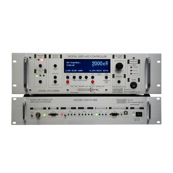
4 Electronics 4.1 LPS300-D and LPS075-D Model LPS300-D is designed to control LEED-AES spectrometers in both LEED and AES regimes. It can be controlled manually using the front panel controls or remotely via USB using a software program. Model LPS075-D is designed to control LEED-AES spectrometers in the LEED mode only. -
Page 16: Rear Panel
highlight a desired program and press Select to confirm. The Save button saves the current displayed voltages and the filament current. Filament, Wehnelt, Focus, Select any of these to be set by the Beam Energy Control Grid2&3, and Screen knob. Beam Energy Control Turn knob to change value of the selected variable (see above). -
Page 17: Electron Gun Pins Assignment
using a PC. Separate ground terminal. 2 A slow blow fuse rated for 100–120 V, or Fuse 1.5 A slow blow fuse rated for 220–240 V. AC In AC input power 3-pole socket. Screen BNC connector, maximum 5 kV DC. 12-pin connector for the electron gun cable. -
Page 18: Detail Description
A lock-in amplifier for phase sensitive detection is built into this unit. It consists of one phase-locked loop (PLL), one phase sensitive detector (PSD), two single-ended analog-to- digital converters (ADC), and two digital-to-analog converters (DAC). Also available are four lines for digital input and four lines for digital output. The PLL can be set to lock either on the fundamental or the second harmonic. - Page 19 Noise Input Impedance AC coupled, 10 nF into 1 MΩ Frequency Range 0.2–7.5 kHz with a typical phase jitter < 0.2% Locks Onto The fundamental or 2 harmonic Chip TI ADS7807 Resolution 16 bits Accuracy ±1.5 LSB max INL Conversion Time 25 μs Chip TI DAC715...
-
Page 21: Operating Instructions
5 Operating Instructions The unit should not be operated at maximum voltages unless it is Note: fully extended (applicable for models equipped with an optional integral linear motion) and has been bake in ultra-high vacuum for extended period of time. The LEED-AUGER spectrometer must be operated at pressure below 1×10 Torr to prevent a destruction of the electron gun filament (1×10... -
Page 22: Quick Start
5.2 Quick Start 5.2.1 Start-up 1. Make sure all cables are properly connected (see Chapter 4 for details). 2. Turn the power on. The instrument will probe the connection with the spectrometer optics. 3. Select Instrument Mode: LEED or AES. 4. -
Page 23: Shutdown
5.2.3 Shutdown 1. Press and hold the Setting button for 2 seconds. All parameters will slowly reduce to zero. 2. Toggle the Power switch off. 5.3 High Voltage Modules The high voltage section of the power supply is protected against overvoltage at three places. These are represented by three LEDs located on the front panel under Protection: Filament Current, Beam Voltage, and Screen Voltage. -
Page 24: Important
5.6.1 Important Open the AES software prior to powering up the LOA10-AES. Make sure the sample is grounded. Set the Ramp Generator End voltage higher than the Start voltage in the AES software. When not measuring, keep the Input of the lock-in open as a transient voltage might damage the input stage of the lock-in. -
Page 25: Lps300-D And Lps075-D
5.8 LPS300-D and LPS075-D The LPS300-D is a powerful and versatile instrument used to control LEED-AES spectrome- ters made by OCI Vacuum Microengineering, while the LPS075-D can only operate in a LEED mode. These power supplies control the following parameters: ... -
Page 26: Monitoring Beam Current
The first thing to do is to set the Instrument Mode (LPS300-D only). This can be done prior to powering up the unit or while it’s running, however, the latter case requires the unit to be restarted. Controller Mode allows the user to OPERate the unit, PROGram its various parameters and features, and diagnostic selfTEST. -
Page 27: Filament Forming
constant at the minimum beam energy. The unit will stop keeping the beam current constant if any of the following occurs: The beam energy falls below 80% of the value at the time of initialization. The focus voltage is decreased below 90% of the value at the time of initialization. ... - Page 28 Before proceeding, set the outgassing timer by changing the Controller Mode to Pro- gramming and selecting Program Selection Outgassing Timer. In the Operating mode, select the Outgassing program and press Timer to start the pro- cedure. Once completed, the unit will revert to a program set previously. Chapter 5 Operating Instructions...
-
Page 29: Programming Menu
6 Programming Menu 6.1 Menu Items The following table gives a brief description of what function do items under Programming mode have. Menu Item Options Description By Filament Automatically adjusts filament current to Constant Beam Mode maintain constant value of beam current. By Wehnelt Automatically adjusts Wehnelt voltage to maintain constant value of beam current. -
Page 30: Menu Map
Max Beam Energy Sets the upper bound for beam energy scan. Scan Max Screen Voltage Sets the maximum allowable screen voltage. Copy Standard to Propagates settings stored in Standard program to Stand-by, LEED1– 5 or AES1–5, and Outgassing. Outgassing Timer Sets for how long outgassing will run as well as a program that will be selected when the outgassing is finished. - Page 31 Chapter 6 Programming Menu...
- Page 32 Chapter 6 Programming Menu...
-
Page 33: Diagrams And Schematics
7 Diagrams and Schematics Chapter 7 Diagrams and Schematics 33... - Page 34 Chapter 7 Diagrams and Schematics...
- Page 35 Chapter 7 Diagrams and Schematics 35...
- Page 36 Chapter 7 Diagrams and Schematics...
- Page 37 Chapter 7 Diagrams and Schematics 37...
- Page 38 Chapter 7 Diagrams and Schematics...
- Page 39 Chapter 7 Diagrams and Schematics 39...
- Page 40 Chapter 7 Diagrams and Schematics...
- Page 41 Chapter 7 Diagrams and Schematics 41...
- Page 42 Chapter 7 Diagrams and Schematics...
- Page 43 Chapter 7 Diagrams and Schematics 43...
- Page 44 Chapter 7 Diagrams and Schematics...
- Page 46 BDL800IR-LMX-ISH BACK VIEW...
-
Page 55: Maintenance
8 Maintenance WARNING: ALL STEPS DESCRIBED BELOW SHOULD ONLY BE TAKEN IN A DUST FREE ENVIRONMENT. OTHERWISE, DUST PAR- TICLES MAY GET INSIDE THE OPTICS AND CAUSE EI- THER DARK OR BRIGHT SPOTS ON THE LEED SCREEN. 8.1 Cleaning Grids The user should have the following tools before attempting to clean the grids: ... -
Page 56: Filament Replacement
7. Use a blow gun (preferably compressed nitrogen) with a filter to gently clean the op- tics’ insides. 8. Use a blow gun to clean the grids and mount them back in the right order. Do not for- get to reconnect Screen, Grid#4, and Grid#2 connections. 9. - Page 57 6. Loosen the telescopic rod at the top by inserting a small stiff wire or a small drill into a hole and rotate counter-clockwise. If you need to replace the silver coated spring wire, repeat. 7. Remove the old electron gun connectors by sliding them off the screw and install new ones.
-
Page 59: Troubleshooting
9 Troubleshooting If your issue is not listed, please contact us directly at +1 (519) 457-0878 or email us at fo@ocivm.com. 9.1 Bright or Dark Spots Both of these phenomena are due to particulate grids contamination. Whether it’s bright or dark depends on which grid the contaminant is attached to. - Page 60 Chapter 9 Troubleshooting...
- Page 61 Chapter 9 Troubleshooting...
Need help?
Do you have a question about the BDL800IR and is the answer not in the manual?
Questions and answers