Table of Contents
Advertisement
Advertisement
Table of Contents

Related Manuals for FireClass J400


Summary of Contents for FireClass J400
- Page 1 FIRECLASS J400 Conventional Fire Panels Installation Manual www.fireclass.net...
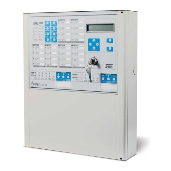
- Page 2 The J424 and J408 Control panels comply with the essential requirements of standards EN54-2; EN54-4; EN12094-1. EN12094-1 certification shall be deemed void if the J400-EXT Extinguishment Module is not installed in the Control panel. The manufacturer reserves the right to change the technical specifications of these products without prior notice.
-
Page 3: Table Of Contents
Installing accessory boards Accessory Items Installing Extinguishment Modules Description Installing Expander Module Kit (for J424 ONLY) 22 Inputs Display Module (for J424 and J400-REP ONLY) 24 Outputs Installing Repeaters Operating features Installing the Control panel Interface Description of the Terminals... - Page 4 PROGRAMMING FROM A PC PROGRAMMING FROM THE PANEL Enrolling: Expander Modules Accessing the Programming session Enrolling: Extinguishment Modules Exiting the Programming Session Activation Mode The “ZONES” Programming Phase Times The “TIMES” Programming Phase Zones The “OUTPUTS” Programming Phase Manual Extinguishment Input The “PANEL”...
-
Page 5: Introduction
The reduced complexity J424 and J408 Fire Control cause unnecessary inconvenience to end-users and panels are the fruit of attentive research and installer serious damage to property. The J400-EXT Extingui- perception. The winning combination of expert wor- shment Module aims at the reducing the false alarm rate... -
Page 6: Outputs
n Outputs n Operating features Pre-alarm If a zone generates an alarm during Day This Control panel accepts devices that operate Mode (Night Mode LED OFF), the Control panel will start within SELV limits ONLY. the Pre-alarm Time. This status will be signalled by: Ø... -
Page 7: Interface
Ø ALARM Ø TROUBLE Display The J424 Control panel can house the J400-LCD Module. This module provides written infor- Silence status will be signalled by: Ø an audible signal (lasting 1 second) followed by a mation regarding the system status, and the cause of faults on inputs and outputs (short-circuit, interruption long pause (lasting 5 seconds);... -
Page 8: Extinguishment Module
Access Level 3 Opening the Control panel: ONLY n Extinguishment Module Qualified persons with authorization are allowed to This section describes how the J400-EXT Extingui- open the Control panel door (requires removal of the shment Module operates. screws) for maintenance purposes. -
Page 9: Identification Of Parts
IDENTIFICATION OF PARTS The Status LEDs Some LEDs indicate more than one status, howe- ver, in most cases the LEDs signal as follows: The following section describes how the Control panel ON (glowing) indicates DISABLED status; LEDs operate, and the actions that can be taken during Fast blinking indicates a FAULT condition;... - Page 10 Pres. Logic Extinguish. Manual Automati valve Ext. Ext. Ext. Switch Unit Extinguish. Extinguish. valve Ext. Ext. Ext. Switch Unit Extinguish. Extinguish Figure 1 Front view of the J424 Control panel J424 (a), J408 Control panel (b) and J400-REP Repeater (c)
- Page 11 Zone Alarm Zone Alarm Fault Alarm Silence Night Mode Logic Unit Pre-al. 24V/24R Ack./Evac. Disab./Fault Test Battery Disab. Ground Reset Disab./Fault Telecom Periph. Telecom Mains Mains Disab. Buzzer Test Disabled/Fault/Test Disabled/Fault/Test Disable Fault Electro- Manual Disab. Pres. Logic Extinguish. Manual Automatic valve Ext.
- Page 12 Figure 2 Maximum configuration of the J424 Control panel...
- Page 13 B016 B– 10 11 12 13 14 15 16 17 18 19 20 21 22 23 24 IDENTIFICATION OF PARTS...
-
Page 14: Description Of Parts
Door screws This section describes the components of the J424 and Keyswitch (Access Level 2) J408 Control panels, and J400-REP Repeater. Display module (accessory item) Expander Control board (LEDs and keys) of Unless otherwise stated, the numbers in boldface in this Expander no. - Page 15 Description Description Anchor for 230 V power supply wires Flat cable (accessory item): for the Extingui- Switching power supply screws shment Module no. 1 to Extinguishment Mo- Switching power supply/Battery charger dule no. 2 connection Switching power supply support Flat cable (accessory item): for the Display Batteries (NOT supplied!): Module connection J408 = two 7 Ah @ 12 V...
- Page 16 Description Anchor screw location holes Chased cable conduit entry RS485 Interface Soldered Earthing screw Figure 4 Maximum configuration of the J400-REP Repeater: a) backplate; b) frontplate (inside view) Conventional Fire Panels J424/J408...
- Page 17 IDENTIFICATION OF PARTS...
- Page 18 Description Battery output voltage control output (connec- ted at factory) Thermal probe jack Switching-power-supply jack (connected at factory) Buzzer Terminal board Extinguishment Module anchor holes Address Jumper: // = Extinguishment Module no. 1 oo = Extinguishment Module no. 2 Terminal board Cable: connects the Switching power supply to the Main board (connected at factory) Switching-power-supply anchor...
- Page 19 Description Expander Module anchor holes (4) Terminal strip Address Jumper: // = Expander Module no. 1 oo = Expander Module no. 2 Expander Control Board anchor holes (4) Jack for the Expander Control Board to Expander Module connection Display Module anchor holes (5) Jack for the connection between the Di- splay Module and the consecutive periphe- ral device...
-
Page 20: Description Of The Control Keys
Fault Electro- Glowing indicates “Extinguishment” in course Fast blinking indicates power supply failure to valve the electrovalve connected to output EV, or that the latter is either open or shorted Glowing indicates “Pre-Extinguishment” in course. Fast blinking indicates that terminals [+] and [–] Ext. -
Page 21: Installing The Control Panel
INSTALLING THE CONTROL PANEL Installing accessory boards Installation of this system must be carried out strictly in accordance with the instructions in this section, and in compliance with the local Ensure that the Control panel power supply safety regulations in force. (Mains and Batteries) has been disconnected before installing any accessory the Modules. -
Page 22: Installing Expander Module Kit (For J424 Only)
4. Using the Jumper (43), marked “1” on the PCB, set up the Extinguishment Module address: Jumper (43) IN = Extinguishment Module nr. 1; Jumper (43) OUT = Extinguishment Module nr. 2. The Jumper (59), marked “2” on the PCB, MUST BE INSERTED. - Page 23 Expander Module Install Expander Modules as follows. Expanders Modules must be installed befo- re mounting the Control panel to the wall. 1. Remove the screws (4) and open the Con- trol panel. 2. Insert the reverse locking supports (93) into their respective locations (94) (as per Fig.
-
Page 24: Display Module (For J424 And J400-Rep Only)
Display Module (for J424 and J400-REP ONLY) The J424 Control panel and the J400-REP Repeater both accept Display Modules (see 6 pages 12 and 16). This instructions in the following section refer to the connection of an LCD Module to a J424 Control pa- nel, the connection procedure for the J400-REP Repeater is similar. -
Page 25: Installing Repeaters
Installing Repeaters Installing the Control panel Work carefully through the following steps (see the Fi- The Display Module (if used) must be installed be- fore the Repeaters. gures on pages 10, 12 and 14). 1. Remove the screws (4) and open the Control panel. Repeaters can be wall mounted, or flush mounted to an ®... -
Page 26: Main Board Terminals
n Main Board Terminals EN 54-2 certification applies ONLY when: no more than 30 devices are connected to each zone; no [24V] [M] Auxiliary Power Supply more than 3 Gas detectors are connected to the Power supply for devices that function at 24 V, protec- Control panel;... - Page 27 [DL] Supervised/Bypassable Dialler Output The ALARM Output accepts devices that operate This Output is for Dialler activation. within SELV limits ONLY. Operating principles This Normally-Open Output (open-collector) will: TROUBLE Silenceable Trouble Output Ø pull down to 0 V (negative) when the Alarm Signal- This Output is for Trouble signalling.
-
Page 28: Extinguishment Module Terminals
PS Supervised Pressure Switch Input NAC1 and NAC2 accept devices that operate wit- hin SELV limits ONLY. This Input is for the Pressure Switch connection. Standby status of this Input can be either Normally n Extinguishment Module Terminals Open (at default) or Normally Closed (refer to “Pressu- re Switch Input”... - Page 29 FIRECLASS J400 Conventional Fire Panels User’s Instructions www.fireclass.net...
- Page 30 Ø a fast intermittent audible signal (0.2 second beep Standby status followed by a 0.2 second pause); Ø an “ALARM” message, similar to the following: During normal operating conditions (Standby status), ONLY the green Mains LED and, if the Control panel is ALARM ON ZONE 01 operating in Night Mode, the Night Mode LED will be Warehouse...
- Page 31 STAT. DISPLAY DESCRIPTION CONSEQUENCE FAULT ON ZONE 01 Disabled A detector is missing from The detectors downstream of Fast Warehouse /Fault zone no. 1, or zone no. 1 is the missing detector will be blink. /Test shorted or open unable to signal fire conditions Logic Unit The Control panel is blocked The Control panel will be una-...
- Page 32 Access Level 2 Silence Most of the functions provided by this Control panel are The Silence button will allow you to stop the signalling available at Access Level 2. Therefore, only Key and devices. To Silence the signalling devices: PIN Code Users can operate the system (PIN Code en- tered or Key turned in the Keyswitch).
- Page 33 n Pre-extinguishment Phase n Disable Extinguish. button If the programmed extinguishment conditions occur This button will allow you to inhibit the Fire Extingui- (programmed by your Installer), the Extinguishment shment systems. Module will generate the Pre-extinguishment phase which will be signalled by: The Disable Extinguish.
- Page 34 EVENTS DETAILS DESCRIPTION 24R OUT FAULT None 24R output is shorted 24R OUT RESTORE None 24R output has been restored 24V OUT FAULT None 24V output is shorted 24V OUT RESTORE None 24V output has been restored ALARM ZONE Zone no. + Description The zone concerned is in Alarm status AUTO UNBYPASSED Extinguishment Mod.
- Page 35 EVENTS DETAILS DESCRIPTION PS ACTIVATED Extinguishment Mod. nr. PS Input of Extinguishment Mod. nr. is operating PS INPUT FAULT Extinguishment Mod. nr. PS Input of Extinguishment Mod. nr. shorted or open PS INPUT RESTORE Extinguishment Mod. nr. PS Input of Extinguish. Mod. nr. executed RESET None Reset executed...
- Page 36 Ack./Evac. ON (glowing) indicates that the program- The Ack./Evac., Silence and Reset buttons can be used during Access Level 2 only. med Investigation time is running. Test ON (glowing) indicates that at least one Zone is in Reset ON (glowing) indicates that Reset cannot be carried out: press the Silence button.
-
Page 37: The System Wiring
AE Silenceable Activated Extinguishment Output DO NOT connect more than 30 devices to each This Output is for “Activated Extinguishment” signal. zone. Operating principles Ø Standby status: negative pull-down to 0 V on the [+] Connect Conventional Fire Detectors as per Figure 14. terminal;... -
Page 38: Connecting Call-Points
Bypass Missing Detectors If this option is enabled, Call-point priority The zone concerned will discrimi- the zone concerned will exclude any inoperative (Mis- nate between alarms triggered by Detectors and those sing) detectors from the system configuration, thus allo- triggered by Call-points. In the event of a Call-point wing detectors connected downstream of ‘Missing’... - Page 39 4 - 20 mA Gas detectors 4 - 20 mA Gas detectors If terminal [P] is used, terminal [A] must also have an 820 ohm resistor. can be connected to terminals [Z1] ONLY on the Main Board and Expander Module, as per Figure 16b. The Repeat Output of the zone can be set up to inter- Operating principles The current draw of terminal [S] varies from 4 to 20 mA...
-
Page 40: Connecting Signalling Devices
RS485 RS485 RS485 RS485 Connect Repeater panel Repeater panel Repeater panel Repeater panel to the earth conductor Figure 17 Wiring diagram of a Repeater connection n Connecting Signalling Devices A 3900 ohm, 1/4 W resistor (109) must be connec- NAC1, NAC2 and ALARM outputs are for the alarm si- ted between the [+] and [–] terminals of the last de- gnalling device connections. -
Page 41: Connecting Extinguishment Modules
n Connecting Extinguishment Modules The wiring diagram in Figure 19 680 W 680 W shows an Extinguishment Module Manual connected to the Control panel. Extinguishment The EM inputs (Manual Extingui- Control Buttons shment) and IE inputs (Inhibit Extin- guishment) accept Normally-Open control buttons with 680 ohm contact resistance. -
Page 42: Connecting A Dialler
Connecting a Dialler An example of how to connect a Dialler is shown in Fi- gure 21. It is assumed that the dialler is activated when terminal L1 goes to negative. Connecting a Power Supply The power circuits of this Control panel comply with the EN54-4 standard. -
Page 43: Connecting The Mains Supply
n Connecting the Mains Supply n Thermal Probe Work carefully through the following steps (refer to the This Control panel supports the KST thermal probe. figures on pages 12, 14, 18 and 19). The probe will optimize the battery charging process by regulating the charge voltage in accordance with the 1. -
Page 44: Maintenance
Maintenance Testing the Extinguishment Module The following operations must carried out regularly. The Extinguishment Module may be tested as descri- bed below. A Using a damp cloth (DO NOT USE SOLVENTS OF ANY KIND), remove dust from the Control panel case. 1. -
Page 45: Programming From A Pc
PROGRAMMING FROM A PC Enrolling: Extinguishment Modules You can program this system from the Control panel or from a computer, using the J400 Console. The Extinguishment Modules page will allow you to This section describes how to program the system from enrol and set up Extinguishment Modules, as follows. -
Page 46: Activation Mode
n Activation Mode Reset Inhibit Time This is the amount of time that This section will allow you to select the logic that will ac- must elapse from the point at which the Extinguishment tivate the Extinguishment phase, as follows. Module is enabled to the point at which the module may be reset. -
Page 47: Enrolling: Repeaters And Lcd Modules
n Thresholds Enrolling: Repeaters and LCD Modules This Control panel can detect whether its Zones are The Repeaters and LCD Modules page will allow you Shorted, Open or in Alarm status by measuring the vol- to enrol Repeater panels and LCD Modules, as follows. tage on the respective Zone terminals. -
Page 48: Options
For step by step instructions on how to set up the Thre- fault), the R Output returns to standby when the Control sholds: panel is reset. — select the “Wizard Thresholds” button. n Times The “Wizard Thresholds” option can be used only Pre-Alarm Time This field will allow you to program the when the Control panel connected to a computer, delay between the Zone Alarm and the Control panel Alarm. -
Page 49: Nac2 Output
n NAC2 Output Fault If you assign this event, the OC Output will acti- vate when the system detects trouble, and will restore Pre-Alarm pattern To be set up in the same way as when the trouble clears. the Pre-Alarm pattern of NAC1 but for the Pre-Alarm pattern of NAC2. -
Page 50: Panel Settings
Panel Settings This process is necessary, as some devices signal trou- ble conditions for several seconds after power-up. The Panel Settings page will allow you to program the following parameters. The Reset section will allow you to program the Detec- tor Reset and Stabilization Times. -
Page 51: Night Mode Silence Time
Downloading Type in the Extinguishment Termination Code than press the Disable Extinguish. button to stop the Extin- guishment Time. Once the operating parameters have been set up, they must be downloaded to the respective Control Panel, When the Extinguishment Termination Code is en- as follows. -
Page 52: Restoring Factory Defaults
5 seconds when the Control panel is in Program- ming status. A series of beeps will signal that the pages, select Configuration from the Pages menu; to Control panel has restored the factory defaults. download All the Pages, select J400 from the Pages menu. Conventional Fire Panels J424/J408... -
Page 53: Accessing The Programming Session
PROGRAMMING FROM THE PANEL Read through the following section carefully, in order to 2. Connect the jumper 65 to the first and second ter- get an overall view of how to use the Programming minal pins on the 3-pin terminal strip marked PRG Overlay during the various “Programming Phases”. -
Page 54: The "Zones" Programming Phase
Œ- Œ- ŒZone 1 ŒZone 5 ‘ Œ2 x N.O. gas Zone 1 Zone 5 Pre-alarm time Investigation time ‘ 640 sec Ž Ž ŽFault Alarm Pre-alarm ‘ 128 sec ŒAlarm verific. ‘ 320 sec ... -
Page 55: The "Outputs" Programming Phase
Œ- Œ- ŒZone 1 ŒZone 5 ‘ 2 x N.O. gas Pre-alarm time Investigation time Zone 1 Zone 5 ‘ 640 sec ŽAlarm ŽPre-alarm ŽFault 128 sec ‘ ŒAlarm verific. ‘ 320 sec User code Day mode ALARM MODULES ‘ Stabilization time Reset time Exting. -
Page 56: User Code (Key/Led 1)
n User Code (Key/LED 1) Delay” has been accepted). Wrong entries will be si- The LED will go On to indicate that the system is ready gnalled by an audible error signal. to start the programming procedure. Using keys 0 thro- ugh 9, type in a 4 digit User Code. -
Page 57: Configuration 1 (Key/Led 5)
n Configuration 1 (Key/LED 5) The “MODULES” Programming Phase The LED will go On to indicate that the system is ready to start the programming procedure. Using the keys in The Activation Mode may ONLY be programmed columns E and F, configure the Control panel: THROUGH A PC. -
Page 58: Man. Preest-Ex. T. (Key/Led 4)
ENTER The LCD Module will allow you to program the following parameters from a J424 Control panel or from a 2. Press Enter to update the Descriptions. J400-REP Repeater panel: Ø LCD Module Address UPDATE Ø Zone Descriptions EXECUTED Ø... -
Page 59: Quick Guide
19,0 V ± 5 % voltage J424 8-Zone Control 0.13 Low voltage ripple Board Suitable batteries: 2 * 12 V/17 Ah 2 * 12 V/7 Ah J400-EXT Extinguishment 0.04 0.21 make YUASA YUASA Module model NP 17-12 FR NP 7-12 FR J400-EXP8 Expander 0.06... - Page 60 TERM. DESCRIPTION v(V) i(A) 2 and 4 ZONE MAIN BOARDS Supervised—Bypassable DIALLER Output: [DL] during Standby è floating on expiry of the Alarm Signalling Delay è negative pull-down to 0 V PROGRAMMABLE AUXILIARY Output: during Standby è terminal floating [OC] on verification of an associated event è...
- Page 61 EXTINGUISHMENT BOARD Supervised—Bypassable MANUAL EXTINGUISHMENT Input: 3.900 ohm (680 ohm se NC) across [+] and [–] terminals è Input in Standby — — 680 ohm (3.900 ohm se NC) across [+] and [–] terminals è PRE-EXTINGUISHMENT time [+] and [–] terminals shorted or open è Manual Extinguishment Fault signalling Supervised INHIBIT EXTINGUISHMENT Input: 3.900 ohm (680 ohm if NC) across [+] and [–] è...
- Page 62 Conventional Fire Panels J424/J408...
- Page 63 QUICK GUIDE...
- Page 64 © FireClass via Gabbiano 22, Z. Ind. S. Scolastica 64013 Corropoli (TE), Italy Hillcrest Business Park Cinderbank Dudley West Midlands DY2 9AP United Kingdom www.fireclass.net ISTISFKEJ408-8 0.0 190313 V10...
Need help?
Do you have a question about the J400 and is the answer not in the manual?
Questions and answers
baixar software