Table of Contents
Advertisement
Quick Links
Instruction Manual
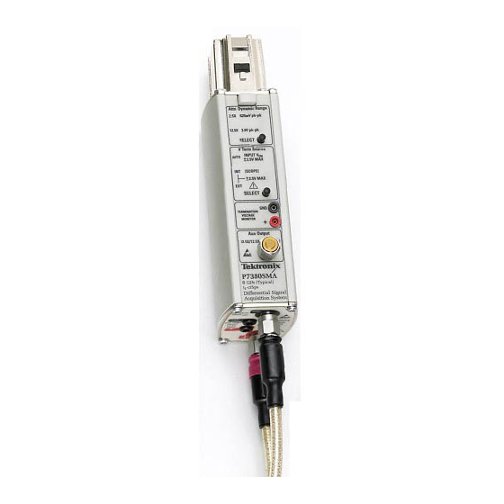
P7380SMA
8 GHz Differential Probe
071-1392-01
Warning
The servicing instructions are for use by qualified
personnel only. To avoid personal injury, do not
perform any servicing unless you are qualified to
do so. Refer to all safety summaries prior to
performing service.
www.tektronix.com
Advertisement
Table of Contents

Related Manuals for Tektronix P7380SMA


Summary of Contents for Tektronix P7380SMA
- Page 1 Instruction Manual P7380SMA 8 GHz Differential Probe 071-1392-01 Warning The servicing instructions are for use by qualified personnel only. To avoid personal injury, do not perform any servicing unless you are qualified to do so. Refer to all safety summaries prior to performing service.
- Page 2 Copyright © Tektronix, Inc. All rights reserved. Tektronix products are covered by U.S. and foreign patents, issued and pending. Information in this publication supercedes that in all previously published material. Specifications and price change privileges reserved. Tektronix, Inc., P.O. Box 500, Beaverton, OR 97077 TEKTRONIX, TEK, and TekConnect are registered trademarks of Tektronix, Inc.
- Page 3 Tektronix, with shipping charges prepaid. Tektronix shall pay for the return of the product to Customer if the shipment is to a location within the country in which the Tektronix service center is located. Customer shall be responsible for paying all shipping charges, duties, taxes, and any other charges for products returned to any other locations.
-
Page 5: Table Of Contents
....Common-Mode Rejection Ratio ..... P7380SMA 8 GHz Differential Probe Instruction Manual... - Page 6 ......... P7380SMA 8 GHz Differential Probe Instruction Manual...
- Page 7 Preparation for Shipment ......P7380SMA 8 GHz Differential Probe Instruction Manual...
- Page 8 ... Table 14: LED error conditions ......P7380SMA 8 GHz Differential Probe Instruction Manual...
- Page 9 ....Figure 35: Preliminary test setup ......P7380SMA 8 GHz Differential Probe Instruction Manual...
- Page 10 ....Figure 44: Test system rise time setup with probe ..P7380SMA 8 GHz Differential Probe Instruction Manual...
-
Page 11: Preface
Preface This is the Instruction Manual for the P7380SMA differential probe. This manual provides operating information, specifications, and performance verification procedures for the probe. P7380SMA 8 GHz Differential Probe Instruction Manual... -
Page 12: Contacting Tektronix
This phone number is toll free in North America. After office hours, please leave a voice mail message. Outside North America, contact a Tektronix sales office or distributor; see the Tektronix web site for a list of offices. P7380SMA 8 GHz Differential Probe Instruction Manual... -
Page 13: General Safety Summary
If you suspect there is damage to this product, have it inspected by qualified service personnel. Do Not Operate in Wet/Damp Conditions. Do Not Operate in an Explosive Atmosphere. Keep Product Surfaces Clean and Dry. P7380SMA 8 GHz Differential Probe Instruction Manual... - Page 14 WARNING indicates an injury hazard not immediately accessible as you read the marking. CAUTION indicates a hazard to property including the product. Symbols on the Product. These symbols may appear on the product: CAUTION Refer to Manual P7380SMA 8 GHz Differential Probe Instruction Manual...
-
Page 15: Service Safety Summary
Service Safety Summary and the General Safety Summary before performing any service procedures. Do Not Service Alone. Do not perform internal service or adjustments of this product unless another person capable of rendering first aid and resuscitation is present. P7380SMA 8 GHz Differential Probe Instruction Manual... - Page 16 Service Safety Summary P7380SMA 8 GHz Differential Probe Instruction Manual...
-
Page 17: Getting Started
Getting Started The P7380SMA is an 8 GHz, active differential probe designed for Serial Data Analysis (SDA) compliance testing and other applica- tions that use differential serial busses in a 50 Ω signaling environ- ment. The SMA input connectors each terminate with an internal 50 Ω... -
Page 18: Probe Controls And Connections
Probe Controls and Connections Table 1 briefly outlines the controls and connections of the P7380SMA differential probe. Additional information can be found later in Getting Started and the following Operating Basics sections. Table 1: P7380SMA features... - Page 19 Auto Mode or EXT Mode exceeds the specified ±2.5 volt range by about 10%. The Overdrive Error LED clears when the range violation signal is removed. For more information, see pages 13 and 47. P7380SMA 8 GHz Differential Probe Instruction Manual...
- Page 20 Disconnect and reconnect the probe to restart the power-on diagnostic sequence. If the LEDs continue to flash, the probe is defective, and must be returned to Tektronix for repair. Termination Voltage Control Mode Select and indicators. The V Term Source Select button allows you to select between three termination voltage control modes—Auto, Internal, and...
- Page 21 If the Attenuation and Termination Source LEDs do not light as described, the host oscilloscope may have stored different attenuation and termination source settings from a previous session. Use the SELECT buttons on the probe to change the settings if necessary. P7380SMA 8 GHz Differential Probe Instruction Manual...
-
Page 22: Standard Accessories
Getting Started Standard Accessories Table 2 shows the standard accessories included with the P7380SMA differential probe. To order replacements, use the Tektronix part number listed with each accessory. Table 2: P7380SMA standard accessories Accessory Description Carrying case with inserts. The soft-sided nylon carrying case has several compartments to hold the probe, accessories, and related documentation. - Page 23 The P7380SMA differential probe includes built-in cable loss compensation when used with the cable assembly. Note: To make DUT connections easier, connect the phase- adjuster ends of the cables to the probe inputs.
-
Page 24: Optional Accessories
Skew on page 58 for instructions. The phase adjuster has a 25 ps adjustment range. The matched-delay SMA cables that come with your probe have a ≤1 ps skew at the cable ends. Tektronix part number: 015-0708-XX (package of 1) P7380SMA 8 GHz Differential Probe Instruction Manual... - Page 25 However, to prevent delay mismatches, do not use the cable included with the P6150 probe. Instead, attach the tips to the ends of the matched SMA cables that are included with the P7380SMA probe. Note: The P6150 probe includes (one) 1X- and (two) 10X- attenuation probe tips.
-
Page 26: Options
Getting Started Options These options are available when ordering the P7380SMA probe: H Option D1- - Calibration Data Report H Option D3- - Calibration Data Report, 3 years (with Option C3) H Option C3- - Calibration Service 3 years H Option D5- - Calibration Data Report, 5 years (with Option C5) -
Page 27: Tekconnect Interface
Getting Started TekConnect Interface The P7380SMA probe is powered through a TekConnect interface between the probe compensation box and the host instrument. The TekConnect interface provides a communication path through contact pins on the host instrument. Power, signal, offset, and probe characteristic data transfer through the interface. -
Page 28: Probe Inputs
Getting Started Probe Inputs The P7380SMA probe has two pairs of input connectors—one for SMA signals and one for external DC termination voltages. Options for the SMA input connections are shown in Figure 3. Dual SMA cables 50 Ω Terminations... -
Page 29: Dc Termination Voltage Control Jacks
2 V for zero-ohm source impedances and about 4 V for 50-ohm source impedances. More exact calculations of the termination network and input load currents can be made using the equations in Table 5 on page 39. P7380SMA 8 GHz Differential Probe Instruction Manual... -
Page 30: Probe Outputs
The attenuation factor of the output signal matches the selected attenuation factor of the probe. This signal can be used to trigger your TDS/CSA 8000 series sampling oscilloscope, or as an input to a spectrum- or network analyzer. P7380SMA 8 GHz Differential Probe Instruction Manual... -
Page 31: Functional Check
011-0060-03 (BNC) Adapter TekConnect-to-SMA Tektronix TCA-SMA Adapter BNC Male-to-SMA Female 015-0572-00 Adapters (2) 0.040 in-to-0.080 in Pin jack 012-1676-XX Nine-digit part numbers (xxx-xxxx-xx) are Tektronix part numbers. Standard accessories included with the probe. P7380SMA 8 GHz Differential Probe Instruction Manual... -
Page 32: Power-On Self Test
This test uses the PROBE COMPENSATION output on the front panel of the oscilloscope to verify that the probe input circuits function. The termination voltage monitor output is also checked, using a DMM. Figure 4 on page 17 illustrates a typical setup. P7380SMA 8 GHz Differential Probe Instruction Manual... -
Page 33: Signal And Termination Voltage Monitor Check
50 Ω Terminations AUTO SMA cable Figure 4: Signal check setup 5. Using the SELECT buttons on the probe, set the attenuation on the probe to 12.5X, and set Vterm source to Auto. P7380SMA 8 GHz Differential Probe Instruction Manual... - Page 34 2.5X attenuator setting will be overdriven and the display will show a limited DC level instead of the probe compensation square wave. You can use a BNC-style 5X attenuator, Tektronix part num- ber 011-0060-03, or SMA-style 5X attenuator, Tektronix part number 015-1002-01.
- Page 35 (displayed on the DMM) approximate those in the table: P7380SMA Probe @ 2.5X Attenuation TDS6604 TDS7704 Signal amplitude 40 mV p-p 100 mV p-p 180 mV --50 mV P7380SMA 8 GHz Differential Probe Instruction Manual...
-
Page 36: Aux Output Check
2. Remove the 50 Ω termination from the Aux output connector. 3. Connect an SMA cable from the probe Aux output to another channel on the oscilloscope, using a Tektronix TCA-SMA adapter. See Figure 5 for the test setup. (You can use the other cable of the matched-delay cable set included with your probe.) - Page 37 Also note that the Aux Output amplitude is attenuated by a factor of 12.5X from that displayed on the P7380SMA main output. This is a result of the intelligent probe interface that adjusts for the selected attenuation factor on the main probe output.
-
Page 38: Dc Termination Voltage Zero Check
0 V. TDS6604 Oscilloscope Use a DMM to monitor V Term Black (- - ) Red (+) 0.040 in-0.080 in Pin jack adapters 50 Ω Terminations Figure 6: DC termination voltage check setup P7380SMA 8 GHz Differential Probe Instruction Manual... - Page 39 0 V. This completes the functional check of the probe. If your instrument supports probe calibration routines, now is a good time to perform them. See Probe Calibration on page 24 for instructions. P7380SMA 8 GHz Differential Probe Instruction Manual...
-
Page 40: Probe Calibration
5. Connect a short-circuit SMA termination to the (- - ) input of the probe. The test setup is shown in Figure 7 on page 25. P7380SMA 8 GHz Differential Probe Instruction Manual... -
Page 41: Figure 7: Probe Calibration Setup
Appendix C: User Service. You can use the probe to make both single-ended and differential measurements. The following pages show some of the ways that you can use your probe. P7380SMA 8 GHz Differential Probe Instruction Manual... -
Page 42: Using The Probe
Aux Out AUTO mode Note: To make DUT connections easier, connect the phase-adjuster ends of the cables to the probe. To circuit under test Figure 8: Using Auto Termination Voltage Control Mode P7380SMA 8 GHz Differential Probe Instruction Manual... -
Page 43: External Mode
Pin jack adapters term on Aux Out EXT mode Black (- - ) Red (+) External DC termination voltage control input terminals To circuit under test Figure 9: Using External Termination Voltage Control Mode P7380SMA 8 GHz Differential Probe Instruction Manual... -
Page 44: Internal Mode
V Term Black (- - ) Red (+) 0.040 in-0.080 in Pin jack adapters Termination on Aux Out INT mode To circuit under test Figure 10: Using Internal Termination Voltage Control Mode P7380SMA 8 GHz Differential Probe Instruction Manual... -
Page 45: Auxiliary Output
See Figure 11. TDS6604 Oscilloscope Spectrum Analyzer RF input SMA cable Aux Out To circuit under test Figure 11: Viewing the Aux Out signal on a spectrum analyzer P7380SMA 8 GHz Differential Probe Instruction Manual... -
Page 46: Using The Probe With A Sampling Oscilloscope
80A05 Clock Recovery Module. By adding an 80A05 Clock Recovery Module to your sampling oscilloscope, you can use the Aux output of your P7380SMA probe to trigger the module on the input signal and view eye diagrams. The 80A05 module generates a recovered clock from an acquired data stream when the data rate is known. -
Page 47: Figure 12: Using The Probe With An 80A03 Interface And An 80A05
SMA cable Circuit under test Aux Out Dual SMA cables Figure 12: Using the probe with an 80A03 Interface and an 80A05 Module to view eye diagrams on a TDS8000 Series sampling oscillo- scope P7380SMA 8 GHz Differential Probe Instruction Manual... -
Page 48: P6150 Probe Tips
Getting Started P6150 Probe Tips The P6150 probe is an optional accessory for the P7380SMA differential probe. The low-capacitance probe tips included with the P6150 probe provide a way for you to take measurements from test points other than SMA connectors. -
Page 49: Operating Basics
An example of the single-ended signals transmitted by an InfiniBand standard driver and the resultant differential signal that would be measured by a differential measurement system is shown in Figure 27 on page 64. P7380SMA 8 GHz Differential Probe Instruction Manual... -
Page 50: Pseudo-Differential Measurements
This measurement technique, which is commonly refered to as pseudo-differential measurement, has a number of limitations when compared to the use of a differential probe like the P7380SMA. In addition to the obvious overhead of two oscilloscope channels for the measurement instead of the single channel needed by a differential probe, there are a number of additional problems. -
Page 51: Differential Probe Measurements
An SMA-input probe like the P7380SMA has a very different input structure. It has a dual, matched 50 Ω input that is designed to terminate the measured signal transmission path with minimum reflections. -
Page 52: Common-Mode Rejection Ratio
(A ). It is expressed either as a ratio or in dB. CMRR(dB) 20 log CMRR CMRR generally is highest (best) at DC and degrades with increasing frequency. P7380SMA 8 GHz Differential Probe Instruction Manual... -
Page 53: Figure 15: Input Termination Network
Operating Basics Figure 28 on page 68 shows the typical CMRR response of the P7380SMA differential probe over frequency. High CMRR in a differential probe requires careful matching of the two input paths. Poorly matched signal source impedances can significantly degrade the CMRR of a measurement. - Page 54 Optional Accessories on page 8. Input Termination Network The input termination network in the P7380SMA differential probe includes a pair of laser trimmed 50 Ω termination resistors, connected together at a common- - mode voltage node, labeled V Figure 15.
-
Page 55: Table 5: Common-Mode Voltage And Current Table
The P7380SMA probe has two attenuation settings, 2.5X and 12.5X, that allow dynamic range to be traded off against signal noise. The 12.5X attenuator setting has the largest dynamic range; the 2.5X attenuator setting has the lowest noise. - Page 56 The maximum input voltage is the maximum voltage to ground that the inputs can withstand without damaging the probe input circuitry. CAUTION. To avoid damaging the inputs of the P7380SMA differen- tial probe, do not apply more than ±5 V (DC + peak AC) between each input and ground.
- Page 57 This results in the terms to be used in the power equations above: Termination input voltage Note: With a balanced DC signal, in the equations above, is half of the value of a conventional differential signal. P7380SMA 8 GHz Differential Probe Instruction Manual...
-
Page 58: Figure 16: Probe Maximum Input Limits
The differential mode signal range is dependent on the probe attenuator setting as shown in Figure 17 on page 43. For a more detailed description of the differential mode dynamic range, see Differential Measurement Topology on page 48. P7380SMA 8 GHz Differential Probe Instruction Manual... -
Page 59: Figure 17: Differential And Common-Mode Operating Ranges
For additional information about CMRR, see page 36. Probe Amplifier Outputs. The P7380SMA probe has a differential signal output. The positive polarity output is connected to the oscilloscope through the TekConnect probe interface. The inverted polarity output is connected to the Aux Output SMA connector on the top of the probe. -
Page 60: Figure 18: Termination Voltage Network Drive
AUTO mode Figure 18: Termination voltage network drive The P7380SMA probe has been designed for compliance testing of high-speed, serial data standards such as PCI Express, InfiniBand, SerialATA, XAUI, Gigabit Ethernet, Fibre Channel, and others. All of these high- - speed, differential data standards define a common- - mode voltage less than the ±2.5 V termination range of the... - Page 61 The black terminal is ground and is connected to the outer case of the shielded module that holds the SMA input terminals. When you are not using these P7380SMA 8 GHz Differential Probe Instruction Manual...
- Page 62 You can use a pair of 0.040 inch-to-0.080 inch pin jack adapters with the 0.080 inch-to-banana plug cables (both are standard accessories included with your probe), to make a more permanent connection to the monitoring DMM. P7380SMA 8 GHz Differential Probe Instruction Manual...
-
Page 63: Figure 19: Overdrive Error Indicator
Operating Basics Overdrive Error The P7380SMA differential probe can measure signals that have a common- - mode voltage range of ±2.5 V. Although the termination voltage range is also specified to be ±2.5 V, limitations on the linear current range of the termination voltage driver restrict the voltage... -
Page 64: Figure 20: Differential Measurement Topology
Operating Basics Differential and Single-Ended Signal Measurement Although designed for differential signal measurement, the P7380SMA probe can be used to make single-ended measurements when properly configured. The analysis that follows describes some differential and single-ended measurements of typical high-speed serial data signals. - Page 65 AC cou- pling. The V compensation circuit in the P7380SMA probe is designed to null out the DC common- - mode component of the input P7380SMA 8 GHz Differential Probe Instruction Manual...
- Page 66 Single-Ended Measurement Topology Although the P7380SMA differential probe can be used to make single-ended measurements, it is important to understand the impact of the termination network on the measured response, particularly on the DC common- - mode component of the signal.
-
Page 67: Figure 21: 50 Ohm Termination On (- ) Input
50 Ω termination resistor inside the probe positive input connector. This matched source impedance topology is the only single-ended topology that can be correctly used with Auto mode. P7380SMA 8 GHz Differential Probe Instruction Manual... -
Page 68: Figure 22: Shorting Termination On (- ) Input
In the special case where the termination voltage is set equal to the common- - mode input voltage, the input signal DC loading is minimized and the measured DC output voltage equals the full P7380SMA 8 GHz Differential Probe Instruction Manual... -
Page 69: Figure 23: Open (- ) Input
50 Ω V out Atten & V comp V- - 50 Ω IN - - V ) x A DC loading on V source: For V case, V Figure 23: Open (- ) input P7380SMA 8 GHz Differential Probe Instruction Manual... - Page 70 Voltage Select to either Int or Ext mode. The termination voltage should be set to the voltage measured in the first step. This can be done easily in Int mode, but requires a TekConnect oscilloscope that has support for probe termination voltage select. P7380SMA 8 GHz Differential Probe Instruction Manual...
-
Page 71: Table 6: Differential To Single-Ended Conversion Table
- mode DC voltage, it should be noted that the use of the 50 Ω termination topology effectively attenuates the DC common- - mode voltage by half. If this is taken into account as an P7380SMA 8 GHz Differential Probe Instruction Manual... - Page 72 Extending the input leads will also increase the skin loss and dielectric loss, which may result in distorted high-frequency pulse edges. You must take into account any effects caused by the extended leads when you take a measurement. P7380SMA 8 GHz Differential Probe Instruction Manual...
-
Page 73: Figure 24: Checking Skew Between Inputs
8). You can measure the skew of a pair of matched cables by connecting the cables to a Tektronix 80E04 Sampling Head, configured for a TDR output. Figure 24 shows a typical setup for checking the skew. 1. Turn on the equipment and let it warm up for 20 minutes. Do not connect the cables to the sampling head yet. - Page 74 2. On the cable with the longer delay, loosen the phase adjuster locking nuts, set the phase adjuster to minimum delay (shortest length), and secure the locking nuts. See Figure 25 on page 59. P7380SMA 8 GHz Differential Probe Instruction Manual...
-
Page 75: Figure 25: Using The Phase Adjuster
6. Confirm that the skew is acceptable after you tighten the locking nuts, as the adjustment may change slightly during tightening. 7. Disconnect the cables from the sampling head, and connect them to the P7380SMA probe head. P7380SMA 8 GHz Differential Probe Instruction Manual... - Page 76 You can measure the skew between two P7380SMA probes by using a Tektronix 80E04 Sampling Head configured for a TDR output. Because the skew of the P7380SMA probe inputs is less than 1 ps, two P7380SMA probes can be deskewed using single-ended drive signals from a dual-channel TDR source.
-
Page 77: Figure 26: Deskewing Two P7380Sma Probes
7. Adjust vertical SCALE, and POSITION (with active probes, adjusting offset may be required) for each channel so that the signals overlap and are centered on-screen. 8. Adjust horizontal POSITION so that a triggered rising edge is at center screen. P7380SMA 8 GHz Differential Probe Instruction Manual... - Page 78 Deskew field and input the time value you measured with the cursors in step 10, or you can use the front-panel or on-screen controls to position the signal. 15. Repeat steps 3 through 14 for each additional channel that you want to deskew. P7380SMA 8 GHz Differential Probe Instruction Manual...
-
Page 79: Table 7: Serial Bus Standards With Dynamic Range Requirements
This section contains reference information about communication standards and related differential measurements. Serial Bus Standards Table 7 lists some popular high-speed data communication standards that can be measured with the P7380SMA differential probe. Table 7: Serial bus standards with dynamic range requirements Standard Data Rate Vdm_max... -
Page 80: Figure 27: Infiniband Signals
- ended signal. 1.075 V 0.75 V 0.425 V (a) Single-ended drive signals +0.65 V diff - - 0.65 V (b) Differential drive signals Figure 27: InfiniBand signals P7380SMA 8 GHz Differential Probe Instruction Manual... -
Page 81: Table 8: Warranted Electrical Characteristics
Appendix A: Specifications The specifications in Tables 8 through 10 apply to a P7380SMA probe installed on a TDS6604 oscilloscope. The probe must have a warm-up period of at least 20 minutes and be in an environment that does not exceed the limits described in Table 8. Specifications for the P7380SMA differential probe fall into three categories: warranted, typical, and nominal characteristics. -
Page 82: Table 9: Typical Electrical Characteristics
≤55 ps, +20 _C to +30 _C (+68 _F to +86 _F) Single-ended rise time, 10--90%, (probe only, Main and Aux output) 250 mV step Differential signal range 0.625 Vp-p (2.5 X attenuation) 3.0 Vp-p (12.5 X attenuation) P7380SMA 8 GHz Differential Probe Instruction Manual... - Page 83 = 0 V, V = ±2.0 V <±5 mV, +20 _C to +30 _C (+68 _F to +86 _F) = ±2.5 V, V = 0 V <±5 mV, +20 _C to +30 _C (+68 _F to +86 _F) P7380SMA 8 GHz Differential Probe Instruction Manual...
-
Page 84: Figure 28: Typical Cmrr Plot
- - 35 - - 40 - - 45 - - 50 - - 55 - - 60 - - 65 - - 70 100 MHz 1 GHz 10 GHz Figure 28: Typical CMRR plot P7380SMA 8 GHz Differential Probe Instruction Manual... -
Page 85: Figure 29: Typical Differential Input Return Loss
- - 19 - - 22 - - 25 - - 28 Gain 20 log - - 31 - - 34 - - 37 100 MHz 1 GHz 10 GHz Figure 30: Typical differential-mode bandwidth P7380SMA 8 GHz Differential Probe Instruction Manual... -
Page 86: Figure 31: Typical Eye Pattern From An Infiniband Signal
Figures 31 and 32 show a typical eye pattern of an InfiniBand signal and the typical step response, as measured with the probe. Figure 31: Typical eye pattern from an InfiniBand signal Figure 32: Typical differential step response P7380SMA 8 GHz Differential Probe Instruction Manual... -
Page 87: Table 10: Nominal Electrical Characteristics
Figure 33 on page 72. Table 11: Typical mechanical characteristics 48.0 mm × 31.8 mm ×129.5 mm Dimensions (1.9 in × 1.3 in × 5.1 in) Unit weight 230 g (0.51 lb) P7380SMA 8 GHz Differential Probe Instruction Manual... -
Page 88: Figure 33: Probe Dimensions
(1.30 in) 129.50 mm (5.10 in) 2.03 mm (.080 in) 7.95 mm Diameter (0.313 in) 48.00 mm (1.90 in) or 52.98 mm 24.13 mm (2.086 in) (0.950 in) W/terminator Figure 33: Probe dimensions P7380SMA 8 GHz Differential Probe Instruction Manual... -
Page 89: Table 12: Equipment Required For Performance Verification
Module with semi-rigid cable above 174-4857-XX cable 0.1 mV and 0.01 Ω DMM (2), with leads Fluke 187 or equivalent resolution Dual Power Supply 5.0 VDC at 200 mA B+K Precision 1760A or equivalent P7380SMA 8 GHz Differential Probe Instruction Manual... - Page 90 103-0028-00 Female SMA torque wrench 5/16-in, 7 in-lb. Nine-digit part numbers (xxx-xxxx-xx) are Tektronix part numbers. This oscilloscope features Int mode control (see page 79 for test). Standard accessory included with the probe. One adapter is included with the probe.
-
Page 91: Figure 34: Tekconnect-To-Sma Adapter
Appendix B: Performance Verification Special Adapters Required Some of the adapters listed in Table 12 are available only from Tektronix. These adapters are described on the following pages. TekConnect-to-SMA Adapter The TekConnect-to-SMA Adapter, Tektronix part number TCA- SMA, allows signals from an SMA cable or probe to be connected to a TekConnect input. -
Page 92: Figure 35: Preliminary Test Setup
6. Photocopy the test record on page 90 to record the performance test results. TDS/CSA 8000 Series Oscilloscope TDS6604 Oscilloscope CH 7, 8 80E04 CH 4 (measurement Module channel) 80A03 80A03 TekConnect Probe Interface P7380SMA probe 80E0X Module Figure 35: Preliminary test setup P7380SMA 8 GHz Differential Probe Instruction Manual... - Page 93 Gently touch the center conductor on each connector, enough to get a measurement. Don’t touch the outer edge of the connector. P7380SMA probe Figure 36: Checking differential mode input resistance P7380SMA 8 GHz Differential Probe Instruction Manual...
- Page 94 Black (- - ) Black (- - ) Red (+) Red (+) Measure Vterm input voltage at External DC input terminals Figure 37: Termination Voltage Accuracy, Ext mode setup P7380SMA 8 GHz Differential Probe Instruction Manual...
- Page 95 Record this value as Vout on the test record. 5. Repeat steps 3 and 4 for the +2.500 volt and - - 2.500 volt input values listed in the test record. P7380SMA 8 GHz Differential Probe Instruction Manual...
- Page 96 3. Set the power supply as close as practical to 0.000 volts, using the DMM to measure this input voltage at the terminals on the power supply. Record this voltage as Vin on the test record. P7380SMA 8 GHz Differential Probe Instruction Manual...
- Page 97 Vout on the test record, and verify that the Vout voltage is within the specified limits in the min/max columns. 5. Repeat steps 3 and 4 for the +2.500 volt and - - 2.500 volt input values listed in the test record. P7380SMA 8 GHz Differential Probe Instruction Manual...
- Page 98 4. Set the multimeter to read DC volts. ± 5. Verify that the output voltage is 0 V, 2.5 mV for both the 2.5X and 12.5X attenuation settings. 6. Record the results on the test record. P7380SMA 8 GHz Differential Probe Instruction Manual...
- Page 99 BNC-to-Dual Cable Banana adapter (- -) Power supply Power supply 80A03 BNC-SMA adapter BNC-to-Dual Banana adapter 50 Ω Precision BNC-to-SMA adapter termination Matched SMA cables P7380SMA probe Figure 40: DC Gain Accuracy setup P7380SMA 8 GHz Differential Probe Instruction Manual...
- Page 100 Figure 41: Reverse the power supply polarity on the probe inputs 8. Record the output voltage (on the second DMM) as V ÷ 9. Calculate the gain as follows: (V 1 - - V 1 - - V P7380SMA 8 GHz Differential Probe Instruction Manual...
- Page 101 5X attenuators must be used when checking the 2.5X attenuation setting on the probe. Rise Time Check at 12.5X Attenuation 1. Remove the probe from the previous test setup. 2. Connect the test equipment as shown in Figure 42 on page 86. P7380SMA 8 GHz Differential Probe Instruction Manual...
- Page 102 3. Turn on Channel 4 and set the vertical scale to 50 mV/div. 4. Set the Channel 7/8 sampling head to TDR mode: Press the SETUP DIALOGS button and select the TDR tab. See Figure 43 on page 87. P7380SMA 8 GHz Differential Probe Instruction Manual...
- Page 103 The sampling module will turn on a red light next to the SELECT channel button, indicating that TDR is activated for that channel. 8. Turn off the display for Channel 7 and 8 so that only Channel 4 is shown on screen. P7380SMA 8 GHz Differential Probe Instruction Manual...
- Page 104 M- - to- - M cables 80A03 TekConnect Probe Interface P7380SMA Probe 80E0X Module Semi- - rigid SMA cable Figure 44: Test system rise time setup with probe 12. Remove the TekConnect-to-SMA adapter from the test setup. P7380SMA 8 GHz Differential Probe Instruction Manual...
- Page 105 23. Install inline 5X attenuators on the TDR outputs. 24. Repeat steps 2 through 14. 25. Set the attenuation on the probe to 2.5X. 26. Repeat steps 16 through 21 for the 2.5X attenuation setting. P7380SMA 8 GHz Differential Probe Instruction Manual...
- Page 106 Vin -- 82 mV Vin______Vout______ Vin + 82 mV 2.5X --2.5 mV +2.5 mV Output offset zero 12.5X --2.5 mV +2.5 mV DC gain 2.5X 0.392 0.408 accuracy 12.5X 0.0784 0.0816 Differential 2.5X 55 ps rise time 12.5X NA 55 ps P7380SMA 8 GHz Differential Probe Instruction Manual...
-
Page 107: Table 13: P7380Sma Probe Compatibiity Issues
This section covers troubleshooting and maintenance for the P7380SMA differential probe. Probe/Adapter/Oscilloscope Compatibility The P7380SMA differential probe is designed to work with all TekConnect-interface oscilloscopes and adapters. However, there may be some cases where all of the probe features may not work properly. -
Page 108: Table 14: Led Error Conditions
If the remedy does not clear the error condition, the probe is defective and must be returned to Tektronix for repair. P7380SMA 8 GHz Differential Probe Instruction Manual... - Page 109 Replacement Parts Due to the sophisticated design of the P7380SMA differential probe, there are no user replaceable parts within the probe. Refer to the Getting Started section for a list of replaceable accessories for your probe.
- Page 110 3. Place the probe into the box and stabilize it with light packing material. 4. Seal the carton with shipping tape. 5. Refer to Contacting Tektronix on page viii for the shipping address. P7380SMA 8 GHz Differential Probe Instruction Manual...
Need help?
Do you have a question about the P7380SMA and is the answer not in the manual?
Questions and answers