Table of Contents
Advertisement
Quick Links
Service Manual
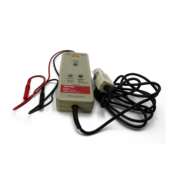
P5210
High Voltage Differential Probe
070-9895-03
Warning
The servicing instructions are for use by qualified
personnel only. To avoid personal injury, do not
perform any servicing unless you are qualified to
do so. Refer to all safety summaries prior to
performing service.
www.tektronix.com
Advertisement
Table of Contents

Subscribe to Our Youtube Channel
Related Manuals for Tektronix P5210


Summary of Contents for Tektronix P5210
- Page 1 Service Manual P5210 High Voltage Differential Probe 070-9895-03 Warning The servicing instructions are for use by qualified personnel only. To avoid personal injury, do not perform any servicing unless you are qualified to do so. Refer to all safety summaries prior to performing service.
- Page 2 Copyright © Tektronix, Inc. All rights reserved. Tektronix products are covered by U.S. and foreign patents, issued and pending. Information in this publication supercedes that in all previously published material. Specifications and price change privileges reserved. Tektronix, Inc., P.O. Box 500, Beaverton, OR 97077 TEKTRONIX, TEK, and TEKPROBE are registered trademarks of Tektronix, Inc.
- Page 3 Tektronix, shipping charges prepaid, and with a copy of customer proof of purchase. Tektronix shall pay for the return of the product to Customer if the shipment is to a location within the country in which the Tektronix service center is located.
-
Page 5: Table Of Contents
......Using the Replaceable Parts List ......P5210 High Voltage Differential Probe Service Manual... - Page 6 ........Mfr. Code to Manufacturer Cross Index ....P5210 High Voltage Differential Probe Service Manual...
- Page 7 Figure 13: Slide probe leads onto the binding posts ..Figure 14: P5210 probe and replaceable accessories ..Figure 15: Replaceable parts - - compensation box .
- Page 8 ..... Table 7: Parts list column descriptions ....P5210 High Voltage Differential Probe Service Manual...
-
Page 9: General Safety Summary
Only qualified personnel should perform service procedures. Observe Maximum Working Voltage Do not use the P5210 High Voltage Differential Probe above 1,000 V CAT III (2,200 V CAT II ) from ground on either input or ±... - Page 10 CAUTION indicates a hazard to property including the product. Symbols on the Product. These symbols may appear on the product: Double CAUTION WARNING Protective Ground Insulated (Earth) Terminal Refer to Manual High Voltage P5210 High Voltage Differential Probe Service Manual...
-
Page 11: Service Safety Summary
Use Care When Servicing with Power On. Dangerous voltages or currents may exist in this product. Disconnect power, remove battery (if applicable), and disconnect test leads before removing protective panels, soldering, or replacing components. To avoid electric shock, do not touch exposed connections. P5210 High Voltage Differential Probe Service Manual... -
Page 12: Contacting Tektronix
This phone number is toll free in North America. After office hours, please leave a voice mail message. Outside North America, contact a Tektronix sales office or distributor; see the Tektronix web site for a list of offices. P5210 High Voltage Differential Probe Service Manual viii... -
Page 13: Operating Basics
Operating Basics To help you use the P5210 High Voltage Differential Probe safely and effectively, this section provides important information about safety limits, operating characteristics, and probing techniques. WARNING. Due to the inherent hazards associated with taking high-voltage measurements, the product is intended for use by qualified personnel who have had the training to make these types of measurements. -
Page 14: Operating The Probe Safely
RMS voltage.) You must also observe the ratings between the differential inputs and between each input and earth ground. CAUTION. To avoid damaging the input circuitry of the P5210, do not apply voltage of more than 2,200 V CAT II between either input... -
Page 15: Figure 1: Safety Limits
1000 V 500 V Voltage (RMS) 100 V 50 V DC or 0 100 k 500 k 10 M 50 M Frequency (Hz) Figure 1: Safety Limits (voltage between either input and earth ground P5210 High Voltage Differential Probe Service Manual... -
Page 16: Operating Characteristics And Probing Techniques
Operating Limits The P5210 has two operating ranges that you select with the ATTENUATION button on the front panel: 1,000X and 100X. These ranges set the maximum differential voltage that can be measured. -
Page 17: Twisting The Input Leads
The extension leads allow you to reach widely spaced connection points. Connect the extension leads to the input leads using the adapters provided. Be sure to use both extension leads so that the input leads are the same length. P5210 High Voltage Differential Probe Service Manual... -
Page 18: Probe Loading
For a graph of frequency versus input impedance, refer to Figure 6 on page 13 of the Specifications section. The probe has virtually no loading effect on sources with relatively low impedance and low frequency. P5210 High Voltage Differential Probe Service Manual... -
Page 19: Specifications
Specifications The specifications in Tables 1 through 5 apply to a P5210 probe installed on a Tektronix TDS 460A oscilloscope. When the probe is used with another oscilloscope, the oscilloscope must have: H An input impedance of 1 MΩ H An input capacitance range of between 15 and 20 pF... -
Page 20: Table 1: Warranted Electrical Characteristics
020-2195-00 accessory kit. If you use any other probe head, do not exceed the voltage-to-ground rating of that probe head or this 2.2 kV CAT II rating. Tektronix Design Standard 062-2847-00 P5210 High Voltage Differential Probe Service Manual... -
Page 21: Figure 4: Safety Limits
1000 V 500 V Voltage (RMS) 100 V 50 V DC or 0 100 k 500 k 10 M 50 M Frequency (Hz) Figure 4: Safety limits (voltage between either input and earth ground P5210 High Voltage Differential Probe Service Manual... -
Page 22: Table 2: Certifications And Compliances
Equipment is usually cord-connected CAT I Secondary (signal level) or battery operated circuits of electronic equipment Pollution Degree 2 Do not operate in environments where conductive pollutants may be present. P5210 High Voltage Differential Probe Service Manual... -
Page 23: Typical Characteristics
Propagation delay 20 nS Overdrive recovery < 50 ns to 10% of final value after 10X overdrive (100X range only) 100X: ± 1.0 V DC offset adjust 1,000X: ± 10 V (referenced to input) P5210 High Voltage Differential Probe Service Manual... -
Page 24: Figure 5: Typical Common-Mode Rejection Ratio
50 dB 60 dB 70 dB 80 dB 90 dB 1 Hz 10 Hz 100 Hz 1 kHz 10 kHz 100 kHz 1 MHz Frequency Figure 5: Typical common-mode rejection ratio (100X attenuation) P5210 High Voltage Differential Probe Service Manual... -
Page 25: Figure 6: Input Impedance Vs. Frequency
315 g (11 oz) Shipping weight (with accessories) 1.42 kg (3 lb, 2 oz) 10 M 100 k 10 k 10 k 100 k 10 M 50 M Frequency (Hz) Figure 6: Input impedance vs. frequency P5210 High Voltage Differential Probe Service Manual... -
Page 26: Nominal Characteristics
1 MΩ oscilloscope input. Load impedance must be greater than 50 kΩ for stated accuracy Gain Switchable: 1/100 (100X) and 1/1,000 (1000X) Overrange beeper Overrange sounds whenever ON, and over range LED is lit. P5210 High Voltage Differential Probe Service Manual... -
Page 27: Maintenance
Do not immerse the probe. Replacing TEKPROBE Interface Pins 1. Remove the interface pin with pliers (see Figure 7 on page 16). 2. Insert a new pin and press it into the socket against a hard surface. P5210 High Voltage Differential Probe Service Manual... -
Page 28: Removing And Replacing The Tekprobe Interface Collar
2. Align the smaller group of pins with the smaller of the two holes in the interface collar and align the tabs with the slots. 3. Gently press the two pieces together (see Figure 8 below). Slot Figure 8: Replacing the TEKPROBE collar P5210 High Voltage Differential Probe Service Manual... -
Page 29: Removing The Compensation Box Covers
Replacing the Compensation Box Covers 1. Carefully align the tab and cover catches. Refer to Figure 10 on page 18. 2. Firmly press the pieces together until the cover catches snap into place. P5210 High Voltage Differential Probe Service Manual... -
Page 30: Figure 10: Replacing The Compensation Box Cover
Maintenance Cover Catches Figure 10: Replacing the compensation box cover P5210 High Voltage Differential Probe Service Manual... -
Page 31: Performance Verification
Performance Verification The following procedure verifies the warranted electrical characteris- tics of the P5210 High Voltage Differential Probe. Table 6 itemizes the equipment required, provides an example or part number of the equipment, and explains the purpose of the equipment. -
Page 32: Construction Of Modified Bnc Adapter
Figure 11: BNC-male-to-dual binding post adapter To expose the posts that you will connect the P5210 High Voltage Differential probe leads to, remove the black and red plastic post covers of the BNC - male - to - dual adapter. Use a pair of pliers and a vise to remove the plastic covers, as shown in Figure 12 on page 22. -
Page 33: Setup
Setup WARNING. These procedures require the application of high voltage to the inputs of the P5210 probe. Because this adapter has exposed metal surfaces, only qualified personnel should perform any testing with voltage levels exceeding 30 V rms. All pertinent safety rules and guidelines for elevated voltage measurements should be followed and adhered to. -
Page 34: Differential Gain Accuracy
4. Connect the coaxial cable from SIG OUT of the generator (rear of Wavetek 9100) to channel 1 of the oscilloscope. 5. Set the generator to 0.1 V and 1 kHz (AUX, square wave, 1 MΩ load). Enable the output. P5210 High Voltage Differential Probe Service Manual... -
Page 35: Figure 13: Slide Probe Leads Onto The Binding Posts
30Vrms. 11. Set the probe to 1000X (out). Set the generator for a 100 V and 1 kHz standard amplitude output (AUX, square wave, 1 MΩ load). P5210 High Voltage Differential Probe Service Manual... -
Page 36: Bandwidth
2. Attach the differential probe input leads without attachment accessories by sliding the banana plug of the leads onto the binding posts metal sleeves on the Modified BNC adapter. P5210 High Voltage Differential Probe Service Manual... -
Page 37: Dc Cmrr
BNC adapter. 6. Adjust the offset on the probe output to zero. WARNING. Generator produces hazardous voltages. To avoid risk of shock, do not touch exposed metal parts after the generator output is enabled. P5210 High Voltage Differential Probe Service Manual... - Page 38 It is recommended that the generator output amplitude be reduced to minimum prior to disabling the output. 11. Disconnect all test equipment. This completes the performance verification procedure. P5210 High Voltage Differential Probe Service Manual...
-
Page 39: Replaceable Parts
Replaceable Parts This section contains a list of the replaceable modules for the P5210 probe. Use this list to identify and order replacement parts. Parts Ordering Information Replacement parts are available through your local Tektronix field office or representative. Changes to Tektronix instruments are sometimes made to accommo- date improved components as they become available and to give you the benefit of the latest circuit improvements. -
Page 40: Table 7: Parts List Column Descriptions
Abbreviations conform to American National Standard ANSI Y1.1- - 1972. Mfr. Code to Manufacturer Cross Index The table titled Manufacturers Cross Index shows codes, names, and addresses of manufacturers or vendors of components listed in the parts list. P5210 High Voltage Differential Probe Service Manual... -
Page 41: Figure 14: P5210 Probe And Replaceable Accessories
Replaceable Parts Figure 14: P5210 probe and replaceable accessories P5210 High Voltage Differential Probe Service Manual... - Page 42 Replaceable Parts P5210 High Voltage Differential Probe Service Manual...
-
Page 43: Figure 15: Replaceable Parts - - Compensation Box
Replaceable Parts P5210 High Voltage Differential Probe Service Manual... -
Page 44: Figure 16: P5210 Probe Optional Accessories
Replaceable Parts P5210 High Voltage Differential Probe Service Manual... - Page 45 Replaceable Parts P5210 High Voltage Differential Probe Service Manual...
- Page 46 Replaceable Parts P5210 High Voltage Differential Probe Service Manual...
Need help?
Do you have a question about the P5210 and is the answer not in the manual?
Questions and answers