
Subscribe to Our Youtube Channel
Related Manuals for S&T kontron KBox B-201-CFL


Summary of Contents for S&T kontron KBox B-201-CFL
- Page 1 USER GUIDE KBox B-201-CFL Doc. User Guide, Rev 1.3 Doc. ID: 1065-0689 www.kontron.com // 1...
- Page 2 KBox B-201-CFL - User Guide, Rev 1.3 This page has been intentionally left blank www.kontron.com // 2...
- Page 3 KBox B-201-CFL - User Guide, Rev 1.3 KBOX B-201-CFL - USER GUIDE Disclaimer Kontron would like to point out that the information contained in this user guide may be subject to alteration, particularly as a result of the constant upgrading of Kontron products. This document does not entail any guarantee on the part of Kontron with respect to technical processes described in the user guide or any product characteristics set out in the user guide.
- Page 4 KBox B-201-CFL - User Guide, Rev 1.3 Intended Use This embedded Box PC, sold by Kontron, is part of Kontron’s B-Series intended for high performance, small form- factor needs with long-term availability. The product can operate in a temperature range from 0°C to plus 45°C; the storage elements can withstand temperatures from minus 20°C to plus 80°C, and a humidity of 10 to 93 percent does not affect the function of the product.
- Page 5 KBox B-201-CFL - User Guide, Rev 1.3 Revision History Revision Brief Description of Changes Date of Issue Author/ Editor Initial version 2019-June-14 Updated product figure (new power button), Ch. 10.2 added 9 Gen. Intel® 2020-Feb-18 Core™ i3/i5/i7 and in Ch. 1 replaced EN 60950-1 with EN 62368-1, expanded Ch.
-
Page 6: Symbols
KBox B-201-CFL - User Guide, Rev 1.3 Symbols The following symbols may be used in this user guide DANGER indicates a hazardous situation which, if not avoided, will result in death or serious injury. WARNING indicates a hazardous situation which, if not avoided, could result in death or serious injury. -
Page 7: For Your Safety
KBox B-201-CFL – User Guide, Rev 1.3 For Your Safety Your new Kontron product was developed and tested carefully to provide all features necessary to ensure its compliance with electrical safety requirements. It was also designed for a long fault-free life. However, the life expectancy of your product can be drastically reduced by improper treatment during unpacking and installation. -
Page 8: Lithium Battery Precautions
KBox B-201-CFL - User Guide, Rev 1.3 Lithium Battery Precautions If your product is equipped with a lithium battery, take the following precautions when replacing the battery. Danger of explosion if the battery is replaced incorrectly. Replace only with same or equivalent battery type recommended by the manufacturer. ... -
Page 9: Table Of Contents
KBox B-201-CFL - User Guide, Rev 1.3 Table of Contents Symbols ..........................................6 For Your Safety ........................................7 High Voltage Safety Instructions .................................. 7 Special Handling and Unpacking Instruction ............................7 Lithium Battery Precautions ..................................8 General Instructions on Usage ..................................8 Quality and Environmental Management .............................. - Page 10 KBox B-201-CFL - User Guide, Rev 1.3 Installation Instructions ................................. 36 8.1. Chassis Feet ....................................... 37 8.1.1. Chassis Feet Mount Option ................................37 8.2. Vertical Stand (Option) ..................................38 8.2.1. Vertical Stand Mount Options ................................38 8.3. Mounting Brackets (Option) ................................39 8.3.1.
-
Page 11: List Of Tables
KBox B-201-CFL - User Guide, Rev 1.3 14.1. Storage ........................................69 14.2. Transportation ....................................... 69 14.3. Maintenance ......................................69 14.3.1. Replacing Lithium Battery................................69 Warranty ......................................70 15.1. Limitation/Exemption from Warranty Obligation ........................70 About Kontron ........................................72 List of Tables Table 1: Scope of Delivery .................................... - Page 12 KBox B-201-CFL - User Guide, Rev 1.3 Figure 15: Air-intake Ventilation Openings .............................. 34 Figure 16: Air-output Ventilation Openings ............................34 Figure 17: Position of Chassis Feet ................................37 Figure 18: Chassis Feet Mount Option ..............................37 Figure 19: Vertical Stand ....................................38 Figure 20: Vertical Stand Screws ................................
-
Page 13: 1/ General Safety Instructions
KBox B-201-CFL - User Guide, Rev 1.3 1/ General Safety Instructions Please read this passage carefully and take careful note of the instructions, which have been compiled for your safety and to ensure to apply in accordance with intended regulations. If the following general safety instructions are not observed, it could lead to injuries to the operator and/or damage of the product;... -
Page 14: Electrostatic Discharge (Esd)
KBox B-201-CFL - User Guide, Rev 1.3 interconnecting power circuits of different products cause no electrical hazards A sufficient dimensioning of the power cable wires must be selected – according to the maximum electrical specifications on the product label – as stipulated by EN62368-1 or VDE0100 or EN60204 or UL61010-1 regulations. -
Page 15: 2/ Introduction
KBox B-201-CFL - User Guide, Rev 1.3 2/ Introduction This user guide describes the KBox B-201-CFL made by Kontron and focuses on describing the KBox B-201-CFL’s special features. New users are recommended to study the installation instructions within this user guide before switching on the power. -
Page 16: 3/ Scope Of Delivery
KBox B-201-CFL - User Guide, Rev 1.3 3/ Scope of Delivery 3.1. Packaging The KBox B-201-CFL is packaged together with all parts, in a product specific cardboard package designed to provide adequate protection and absorb shock. 3.2. Unpacking To unpack the KBox B-201-CFL, perform the following: Remove packaging. -
Page 17: Product Identification Type Label
KBox B-201-CFL - User Guide, Rev 1.3 3.5. Product Identification Type Label The type label defines the product’s mainboard variants Smart or Value and the power variant 12 VDC or 24 VDC, and contains specific product information (Model, Power Product Number, Serial Number, Electrical Specification and Compliance.). -
Page 18: 4/ Product Features
KBox B-201-CFL - User Guide, Rev 1.3 4/ Product Features Before working with the KBox B-201-CFL, Kontron recommends that users take a few minutes to study this chapter and learn about the product’s various parts and features. Figure 3: KBox B-201-CFL Overview www.kontron.com // 18... -
Page 19: Front Side Features
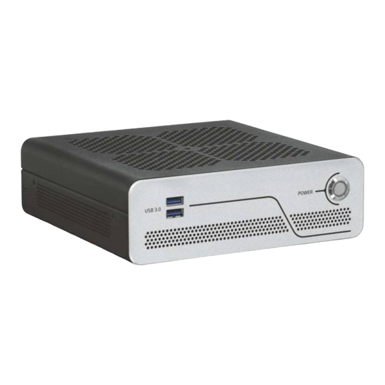
KBox B-201-CFL - User Guide, Rev 1.3 4.1. Front Side Features The front side contains the power-on button, two USB 3.1 Gen 1 ports, and ventilation openings for air-output. Figure 4: Front Side 2x USB 3.1 Gen 1 ports Power-on button with power LED Ventilation openings (air-output) 4.1.1. -
Page 20: Rear Side Features
KBox B-201-CFL - User Guide, Rev 1.3 4.2. Rear Side Features The rear panel contains the main I/O interfaces, power-in connector (DC-IN), ventilation openings for air-output and two top cover fastening screws. The KBox B-201-CFL ‘Smart’ and ‘Value’ mainboard variants support different rear panel I/O interfaces, see Figure 5 and Figure 6. -
Page 21: Rear Panel Connectors
KBox B-201-CFL - User Guide, Rev 1.3 Figure 6: Rear Panel KBox B-201-CFL (Value) PS/2 Keyboard DVI-D 11 Audio line-out 12 2x Top cover screws PS/2 Mouse 2x LAN ports (GbE) 13 Breakout for Wi-Fi antenna 1x USB 2.0 2x USB 2.0 ports 14 DC-IN power connector 1x DP 2 x USB 3.1 Gen 1 ports... - Page 22 KBox B-201-CFL - User Guide, Rev 1.3 4.2.1.4. DP The Display Port (DP) enables the connection of external digital displays. The DP V 1.2 port is Dual mode/ DP++ compatible, enabling the support of DP to HDMI (passive + active), DP to DVI (passive + active) and DP to VGA (active only) adapters.
- Page 23 KBox B-201-CFL - User Guide, Rev 1.3 To enhance the USB compatibility it is possible to reduce the USB 3.1 Gen 2 port default setting of 10 Gbits/s to 5 Gbits/s in the BIOS setup Advanced>USB Configuration>USB 3.1 Gen 2 Speed. For the pin assignment, see Chapter 11.2: USB 3.1 Gen 1 Port &...
-
Page 24: Left And Right Side Features
KBox B-201-CFL - User Guide, Rev 1.3 4.3. Left and Right Side Features The right and left sides contain ventilation openings for air-output. The two threaded screw holes available on both sides (Figure 7, pos. 2) are used to attach the mounting brackets, see Chapter 8.3: Mounting Brackets (Option) or alternatively to attach the vertical stand, see Chapter 8.2: Vertical Stand (Option). -
Page 25: Top Cover And Bottom Side Features
KBox B-201-CFL - User Guide, Rev 1.3 4.4. Top Cover and Bottom Side Features The top cover consisting of a metal plate with air-intake ventilation openings with a separate metal plate underneath including a circular opening above the internal fan. Figure 8: Top View Circular opening on metal plate Ventilation openings (air-intake) -
Page 26: 5/ System Extension
KBox B-201-CFL - User Guide, Rev 1.3 5/ System Extension 5.1. External Storage 5.1.1. 2.5” SSD Drive Bay The external 2.5” SSD drive bay uses the SATA interface (SATA III / SATA-600 compliant) for 512 GByte or 1 TByte 2.5” SSD drives. 5.2. -
Page 27: Socket
KBox B-201-CFL - User Guide, Rev 1.3 5.2.2. M.2 Socket The onboard M.2 Key M socket supports: KBox B-201-CFL (Smart) KBox B-201-CFL (Value) 1x M.2 (Key-M) modules 1x M.2( Key-M) modules 2280/2260/2242 form factor 2280/2260/2242 form factor ... -
Page 28: 6/ Accessing Internal Components
KBox B-201-CFL - User Guide, Rev 1.3 6/ Accessing Internal Components This chapter contains important information that you must read before accessing internal components. Take care to follow these procedures properly when accessing or installing internal components. It is recommended to expand your product with expansion options before mounting the product. -
Page 29: Figure 10: Top Cover Fastening Screws
KBox B-201-CFL - User Guide, Rev 1.3 To open the chassis, perform the following: Close all applications. Shut down the product properly and disconnect the power cable from the power source. Disconnect all peripherals. Place the KBox B-201-CFL on a flat, clean and ESD-safe surface. Remove the two top cover screws on the rear panel (Figure 10) and retain the screws to secure the top cover later. -
Page 30: Opening And Closing Ssd Drive Bay Cover
KBox B-201-CFL - User Guide, Rev 1.3 6.2. Opening and Closing SSD Drive Bay Cover Before opening the SSD drive bay, observe to the safety instructions at the start of this chapter. Before installing a 2.5” SSD, observe the manufacturer’s instructions. To open the SSD drive bay, perform the following: Close all applications. -
Page 31: Installing And Removing Externally Accessible 2.5" Ssd
KBox B-201-CFL - User Guide, Rev 1.3 6.2.1. Installing and Removing Externally Accessible 2.5” SSD To install a 2.5” SSD, perform the following: Open the SDD drive bay cover by following the instructions in Chapter 6.2: Opening and Closing SSD Drive Bay Cover (steps 1 to 6). -
Page 32: Installing And Removing Internal M.2 Ssd
KBox B-201-CFL - User Guide, Rev 1.3 6.3. Installing and Removing Internal M.2 SSD To install an M.2 module, perform the following: Open the chassis as described in Chapter 6.1: Opening and Closing the Chassis, (opening procedure: steps 1 to 5). Locate the M.2 socket and the corresponding spacer bolt. - Page 33 KBox B-201-CFL - User Guide, Rev 1.3 To remove a mPCIe card, perform the following: Open the chassis as described in Chapter 6.1: Opening and Closing the Chassis (opening procedure: steps 1 to Locate the installed mPCIe card. Remove the mountings screw and spacer, and the mPCIe card springs up at the free end. Gently pull out the mPCIe card from the socket.
-
Page 34: 7/ Thermal Considerations
KBox B-201-CFL - User Guide, Rev 1.3 7/ Thermal Considerations 7.1. Active Cooling The KBox B-201-CFL is actively fan cooled. Air enters through the top cover’s ventilation openings, (Figure 15, pos. 1) and is distributed over the mainboard by an internal fan before exiting ventilation openings on the right, left, front and rear sides (Figure 16, pos. -
Page 35: Minimum System Clearance (Keep Out Area)
KBox B-201-CFL - User Guide, Rev 1.3 7.2. Minimum System Clearance (Keep out Area) To provide maximum airflow through and around the KBox B-201-CFL, a minimum distances to the surrounding environment must be observed know as keep out area in this user guide. Before installing the KBox B-201-CFL, ensure that the keep out areas (see Figure 23 and Figure 24) have been taken into consideration. -
Page 36: 8/ Installation Instructions
KBox B-201-CFL - User Guide, Rev 1.3 8/ Installation Instructions The KBox B-201-CFL can operate horizontally (upward orientation only) and vertically when mounted on a desk, wall or rear side of a monitor. The KBox B-201-CFL is supplied with four chassis feet. Optional installation accessories are a vertical stand, wall mount brackets, and a VESA 100 mount assembly. -
Page 37: Chassis Feet
KBox B-201-CFL - User Guide, Rev 1.3 • Install Wi-Fi antenna on the rear panel (clearance 45 mm and 130 mm from Wi-Fi hinge) Expansion cards and memory installation should be performed before Installation. 8.1. Chassis Feet To use the KBox B-201-CFL on a desktop, install the supplied four self-adhesive chassis feet as follows: Ensure that the bottom surface is clean and free from dust and dirt. -
Page 38: Vertical Stand (Option)
KBox B-201-CFL - User Guide, Rev 1.3 8.2. Vertical Stand (Option) The KBox B-201-CFL can be positioned vertically using a vertical stand (Figure 19). Figure 19: Vertical Stand Vertical stand screw holes To mount the KBox B-201-CFL on the vertical stand: Position with the chassis side on which the vertical stand is to be fastened, facing upwards. -
Page 39: Mounting Brackets (Option)
KBox B-201-CFL - User Guide, Rev 1.3 8.3. Mounting Brackets (Option) To mount on a wall (vertically or horizontally) or fix on a desktop (underneath or topside) use the mounting brackets. Figure 22: Mounting Bracket Mounting holes (10 mm keep out area) Key mounting holes for mount surface Mounting holes (no keep out area) Each mounting bracket supports two sets of holes. -
Page 40: Figure 23: Keep Out Areas - With Top Cover Facing The Mount Surface
KBox B-201-CFL - User Guide, Rev 1.3 Figure 23: Keep Out Areas – with Top Cover facing the Mount Surface 10 mm Keep Out Areas 10 mm (top cover, right & left sides) 10 mm 10 mm 10 mm 10 mm 10 mm Keep Out Areas (front &... -
Page 41: Mounting Brackets Mount Options
KBox B-201-CFL - User Guide, Rev 1.3 8.3.1. Mounting brackets Mount Options Figure 25: Mounting Brackets Desktop Mount Options Mounted (fixed) on a desktop Mounted (fixed) underneath a desktop Danger of Fire If mounted horizontally with top cover facing downward, the KBox B 201-CFL may overheat and hot substances may exit through the top cover’s ventilation openings causing a fire hazard. -
Page 42: Vesa 100 Mount Assembly (Option)
KBox B-201-CFL - User Guide, Rev 1.3 8.4. VESA 100 Mount Assembly (Option) The VESA mount assembly mounts the KBox B-201-CFL and external power supply on the rear side of a VESA 100 monitor. Figure 27: VESA Mounting Assembly Kit The VESA 100 mount assembly kit contains: VESA 100 mounting frame Hook and loop band... -
Page 43: Figure 29: Inserting The Band
KBox B-201-CFL - User Guide, Rev 1.3 Figure 29: Inserting the Band Threading slots on the left and right aligning brackets D-ring Double back with the flexible hook and loop band and feed the rough end through the band’s D-ring. Pull the band through the D-ring and press approximately 30 mm to 50 mm of the self-gripping sides together to form a loose loop. -
Page 44: Vesa 100 Mount Options
KBox B-201-CFL - User Guide, Rev 1.3 8.4.1. VESA 100 Mount Options The VESA 100 mount assembly mounts either directly on the rear side of the monitor, see Chapter 8.4.1.1: Mounting on non VESA Mount Stand Monitor or on the rear side of the monitor using the monitors stand, see Chapter 8.4.1.2: Mounting on Monitor with VESA 100 Stand. -
Page 45: Figure 34: Vesa Monitor Stand Assembly
KBox B-201-CFL - User Guide, Rev 1.3 Feed the supplied four supplied (M4x 20 mm) screws through the four mounting holes on the monitor’s stand and attach one of the supplied spacers to the screw’s free end (Figure 34) Figure 34: VESA Monitor Stand Assembly First insert the free end of the screw (with spacer) through the four mount hole on the VESA mount frame and then onto the VESA 100 mount hole on the back of the monitor. -
Page 46: Connecting The Wi-Fi Antenna (Option)
KBox B-201-CFL - User Guide, Rev 1.3 8.5. Connecting the Wi-Fi Antenna (option) To use the Wi-Fi feature, install the two Wi-Fi antennas included in the scope of delivery to the two Wi-Fi antenna connectors on the rear side of the KBox B-201-CFL. Note that installing the Wi-Fi antenna increases the original keep out area on the rear side from 10 mm to approximately 45 mm. -
Page 47: 9/ Starting Up
KBox B-201-CFL - User Guide, Rev 1.3 9/ Starting Up The KBox B-201-CFL comes hardware configured, and on request with a pre-installed Operating System (OS) and all the necessary drivers (in accordance with the ordered hardware configuration); enabling full operation when switched on for the first time. -
Page 48: Figure 36: 24 Vdc Wired Power Cable
KBox B-201-CFL - User Guide, Rev 1.3 Figure 36: 24 VDC Wired Power Cable Mating connector to DC_IN Wires ferrules for 24 VDC source. Black wire (-) & white wire (+) To connect the 24 VDC power cable, perform the following: Set up the product with any expansion devices and SSDs. -
Page 49: Power On/Off Procedure
KBox B-201-CFL - User Guide, Rev 1.3 9.3. Power On/Off Procedure To switch on the KBox B-201-CFL, connect to the power source as described in Chapter 9.1: Connecting the External Power Connection, and briefly press the power-on button (Figure 4, pos. 3) .The power-on button lights up blue to indicate the powered on state. -
Page 50: 10/ Technical Data
KBox B-201-CFL - User Guide, Rev 1.3 Technical Data 10.1. Block Diagrams Figure 37: Block Diagram of KBox B-201-CFL Smart Variant KBox B-201-CFL (Smart) 2x DisplayPort Dual Channel DDR4-2666 8th / 9th Gen. Intel® Core™ UDIMM DVI-D i3/i5/i7 (up to 32 GB) 2x LAN (GbE) 2x USB 3.1 Gen 1 Front panel... -
Page 51: Figure 38: Block Diagram Of Kbox B-201-Cfl Value Variant
KBox B-201-CFL - User Guide, Rev 1.3 Figure 38: Block Diagram of KBox B-201-CFL Value Variant KBox B-201-CFL (Value) DisplayPort Dual Channel 8th / 9th Gen. DDR4-2666 Intel® Core™ UDIMM DVI-D i3/i5/i7 (up to 32 GB) 2x USB 3.1 Gen 1 2x LAN (GbE) Front panel Power Button &... -
Page 52: Technical Specification
KBox B-201-CFL - User Guide, Rev 1.3 10.2. Technical Specification Table 3: Mainboard Specification KBox B-201-CFL (Smart) KBox B-201-CFL (Value) Mainboard Type D3633-S D3634-S Form Factor Mini-ITX (170mm x 170 mm) ( 6.7“ x 6.7“) Mini-ITX (170mm x 170 mm) ( 6.7“ x 6.7“) Processor Gen. -
Page 53: Table 6: Interface Specifications
KBox B-201-CFL - User Guide, Rev 1.3 Table 6: Interface Specifications KBox B-201-CFL (Smart) KBox B-201-CFL (Value) External Interfaces (front side) USB 3.0 2x USB 3.1 Gen 1 2x USB 3.1 Gen 1 External Interfaces (rear side) USB 3.0 2x USB 3.1 Gen 1 2x USB 3.1 Gen 1 2x USB 3.1 Gen 2 USB 2.0... -
Page 54: Mechanical Specification
KBox B-201-CFL - User Guide, Rev 1.3 10.3. Mechanical Specification The mechanical specification of the KBox B-201-CFL and the possible mounting options is shown in Table 8: Mechanical Specification. Table 8: Mechanical Specifications KBox B-201-CFL Dimensions Depth 190 mm (7.48”) Width 190 mm (7.48”) Height... -
Page 55: Figure 41: Dimensions Top Cover
KBox B-201-CFL - User Guide, Rev 1.3 6.5 mm Figure 41: Dimensions Top Cover 190 mm 190 mm Figure 42: Dimensions Bottom Side 130 mm 190 mm 6.5 mm 130 mm Figure 43: Dimensions Right Side and Left Side 6.5 mm 6.5 mm 190 mm 190 mm... -
Page 56: Dimension Diagrams- Wall Mount Brackets
KBox B-201-CFL - User Guide, Rev 1.3 60 mm 10.3.2. Dimension Diagrams- Wall Mount Brackets The dimension drawing shows the main mounting bracket mechanical dimension. Figure 44: Dimensions with Mounting Brackets Ø 4.5mm 230 mm 10.5 mm Ø 8.5 mm 160 mm 190 mm 250 mm... -
Page 57: Table 10: Directives And Standards Compliance
KBox B-201-CFL - User Guide, Rev 1.3 Kontron is not responsible for any radio television interference caused by unauthorized modifications of the product or the substitution or attachment of connecting cables and equipment other than those specified by Kontron. The correction of interference caused by such unauthorized modification, substitution or attachment will be the responsibility of the user. -
Page 58: Power Specification
KBox B-201-CFL - User Guide, Rev 1.3 10.6. Power Specification The KBox B-201-CFL power connection variants (12 VDC and optional 24 VDC) both connected to the DC-IN power connector.The KBox B-201-CFL power variants are not interchangeable, due to additional internal components in the 24 VDC variant. -
Page 59: Power Protection
KBox B-201-CFL - User Guide, Rev 1.3 10.6.3. Power Protection The external power supply incorporates protection and supply features such as over current, over temperature , over voltage and brownout protection, to protect the product against fluctuations and interruptions in the delivered mains power supply and help to ensure operation without loss of data or damage to the product. -
Page 60: 11/ External Interface - Pin Assignments
KBox B-201-CFL - User Guide, Rev 1.3 11/ External Interface - Pin Assignments 11.1. DC-IN Power Connector Pin Assignment The DC-IN power connector is a barrel jack (5.5 mm/ 2.5 mm) with center pole. Connect the supplied power connection method to the DC-IN connector. The DC-In power connection depends KBox B-201-CFL’S power variant where the standard 12 VDC variant is an external AC/DC power supply and the optional variant is wired 24 VDC. -
Page 61: Usb 2.0 Port Pin Assignment
KBox B-201-CFL - User Guide, Rev 1.3 11.3. USB 2.0 Port Pin Assignment Table 17: USB 2.0 Connector Pin Assignment Signal Name USB 2.0 (Type A) Connector +5 V (fused protected) Data- Data+ Low-active signals are indicated by a minus sign. 11.4. -
Page 62: Display Port (Dp) V1.2 Connector Pin Assignment
KBox B-201-CFL - User Guide, Rev 1.3 11.5. Display Port (DP) V1.2 Connector Pin Assignment Table 20: Display Port (DP) Connector Pin Assignment Signal Name Display Port Connector Signal Name Link0+ Link0- Link1+ Link1- Link2+ Link2- Link3+ Link3- DVI dongle detect AUX+ AUX- Hot Plug detect... -
Page 63: Ps/2 Keyboard Connector Pin Assignment
KBox B-201-CFL - User Guide, Rev 1.3 11.7. PS/2 Keyboard Connector Pin Assignment Table 22: PS/2 Keyboard Connector Pin Assignment Signal Name PS/2 Keyboard Connector Data +5V (fuse protected) Clock Keyboard-On ( low asserted pulse) 11.8. PS/2 Mouse Connector Pin Assignment Table 23: PS/2 Mouse Connector Pin Assignment Signal Name PS/2 Mouse Connector... -
Page 64: Serial Port Connector Pin Assignment
KBox B-201-CFL - User Guide, Rev 1.3 11.10. Serial Port Connector Pin Assignment Table 25: Serial Interface COM1 port (RS232) Connector Pin Assignment Signal Name- RS232 Description 9-pin D-SUB Connector Data Carrier Detect Signal In SOUT Signal out Data Terminal Ready Ground Data Set Ready Request to Send... -
Page 65: 12/ Bios
KBox B-201-CFL - User Guide, Rev 1.3 BIOS The KBox B-201-CFL uses the AMI Aptio 5.x (uEFI) BIOS supported by the D3633-S and D3634-S mainboards and featuring a variety of enhanced functions specifically tailored to the KBox B-201-CFL’s hardware features: ... -
Page 66: Bios Update
KBox B-201-CFL - User Guide, Rev 1.3 The KBox B-201-CFL uEFI BIOS setup program uses a hot key navigation system. The hot key legend bar is located at the bottom of the setup screens. The following table provides a list of navigation hot keys available in the legend bar. Table 26: Navigation Hot Keys Available in the Legend Bar Hot key Description... - Page 67 KBox B-201-CFL - User Guide, Rev 1.3 To update the BIOS using the Windows DeskFlash program, perform the following: Click on “BIOS Update-Windows”. Download the “Flash BIOS Update – Desk Flash Instant” update file. Run the update file “Flash BIOS Update – Desk Flash Instant”. Perform the on-screen instructions.
-
Page 68: 13/ Technical Support
KBox B-201-CFL - User Guide, Rev 1.3 Technical Support For technical support contact our Support department: E-mail: support@kontron.com Phone: +49-821-4086-888 Make sure you have the following information available when you call: Product ID Number (PN) Serial Number (SN) The serial number can be found on the system’s type label. -
Page 69: 14/ Storage, Transportation And Maintenance
KBox B-201-CFL - User Guide, Rev 1.3 Storage, Transportation and Maintenance 14.1. Storage If the product is not in use for an extended period time, disconnect the power plug from the mains power source .If it is necessary to store the product then re-pack the product as originally delivered to avoid damage. The storage facility must meet the products environmental storage requirements as stated within this user guide. -
Page 70: 15/ Warranty
KBox B-201-CFL - User Guide, Rev 1.3 Warranty Kontron defines product warranty in accordance with regional warranty definitions. Claims are at Kontron’s discretion and limited to the defect being of a material nature. To find out more about the warranty conditions and the defined warranty period for your region, following the steps below: Visit Kontron’s Term and Conditions webpage. -
Page 71: Table 27: List Of Acronyms
KBox B-201-CFL - User Guide, Rev 1.3 List of Acronyms Table 27: List of Acronyms ACPI Advanced Configuration Power Interface mSATA Mini SATA AHCI SELV Advanced Host Controller Interface Separate Extra Low Voltage BIOS Basic Input Output System S.M.A.R.T Self-Monitoring, Analysis and Reporting Technology BlueTooth Serial Number... -
Page 72: About Kontron
KBox B-201-CFL – User Guide, Rev 1.3 About Kontron Kontron is a global leader in IoT/Embedded Computing Technology (ECT). As a part of technology group S&T, Kontron, together with its sister company S&T Technologies, offers a combined portfolio of secure hardware, middleware and services for Internet of Things (IoT) and Industry 4.0 applications. With its standard products and tailor-made solutions based on highly reliable state-of-the-art embedded technologies, Kontron provides secure and innovative applications for a variety of industries.
Need help?
Do you have a question about the kontron KBox B-201-CFL and is the answer not in the manual?
Questions and answers