Sign In
Upload
Manuals
Brands
S&T Manuals
Desktop
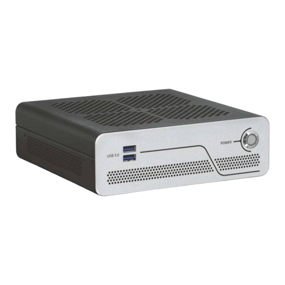
kontron KBox B-201-CFL
S&T kontron KBox B-201-CFL Box PC Manuals
Manuals and User Guides for S&T kontron KBox B-201-CFL Box PC. We have
1
S&T kontron KBox B-201-CFL Box PC manual available for free PDF download: User Manual
S&T kontron KBox B-201-CFL User Manual (72 pages)
Brand:
S&T
| Category:
Desktop
| Size: 4 MB
Table of Contents
Symbols
6
For Your Safety
7
High Voltage Safety Instructions
7
Special Handling and Unpacking Instruction
7
Lithium Battery Precautions
8
General Instructions on Usage
8
Quality and Environmental Management
8
Disposal and Recycling
8
WEEE Compliance
8
Table of Contents
9
List of Tables
11
List of Figures
11
1 / General Safety Instructions
13
Electrostatic Discharge (ESD)
14
Grounding Methods
14
Instructions for the Lithium Battery
14
2 / Introduction
15
Figure 1: Kbox B-201-CFL
15
3 / Scope of Delivery
16
Packaging
16
Unpacking
16
Accessories
16
Table 1: Scope of Delivery
16
Table 2: Accessories
16
Product Identification Type Label
17
Figure 2: Type Label
17
4 / Product Features
18
Figure 3: Kbox B-201-CFL Overview
18
Front Side Features
19
Front Connectors and Buttons
19
Figure 4: Front Side
19
Rear Side Features
20
Figure 5: Rear Panel Kbox B-201-CFL (Smart)
20
Rear Panel Connectors
21
Figure 6: Rear Panel Kbox B-201-CFL (Value)
21
Left and Right Side Features
24
Figure 7: Left Side and Right Side Views
24
Top Cover and Bottom Side Features
25
Figure 8: Top View
25
Figure 9: Bottom View
25
5 / System Extension
26
External Storage
26
SSD Drive Bay
26
Internal Expansion
26
Mpcie Socket
26
Socket
27
6 / Accessing Internal Components
28
Opening and Closing the Chassis
28
Figure 10: Top Cover Fastening Screws
29
Figure 11: Holding Brackets
29
Opening and Closing SSD Drive Bay Cover
30
Figure 12: SSD Drive Bay Cover Rear Side
30
Figure 13: SSD Drive Bay Cover Top Side
30
Installing and Removing Externally Accessible 2.5" SSD
31
Figure 14: SSD Drive Bay with SSD
31
Installing and Removing Internal M.2 SSD
32
Installing and Removing Internal Mpcie Expansion Card
32
7 / Thermal Considerations
34
Active Cooling
34
Figure 15: Air-Intake Ventilation Openings
34
Figure 16: Air-Output Ventilation Openings
34
Minimum System Clearance (Keep out Area)
35
Third Party Components
35
8 / Installation Instructions
36
Chassis Feet
37
Chassis Feet Mount Option
37
Figure 17: Position of Chassis Feet
37
Figure 18: Chassis Feet Mount Option
37
Vertical Stand (Option)
38
Vertical Stand Mount Options
38
Figure 19: Vertical Stand
38
Figure 20: Vertical Stand Screws
38
Figure 21: Vertical Stand Mount Options
38
Mounting Brackets (Option)
39
Figure 22: Mounting Bracket
39
Figure 23: Keep out Areas - with Top Cover Facing the Mount Surface
40
Figure 24: Keep out Areas - with Bottom Side Facing the Mount Surface
40
Mounting Brackets Mount Options
41
Figure 25: Mounting Brackets Desktop Mount Options
41
Figure 26: Mounting Brackets Wall Mount Options
41
VESA 100 Mount Assembly (Option)
42
Figure 27: VESA Mounting Assembly Kit
42
Figure 28: Kbox B-201-CFL Mounting Position
42
Figure 29: Inserting the Band
43
Figure 30: Positioning the Power Supply
43
Figure 31: Kbox B-201-CFL and Power Supply Mounting Position
43
VESA 100 Mount Options
44
Figure 32: Non VESA Stand Monitor Assembly
44
Figure 33: Installed VESA 100 Mount Assembly - Non VESA Stand Monitor
44
Figure 34: VESA Monitor Stand Assembly
45
Figure 35: Installed VESA 100 Mount Assembly - Non VESA Stand Monitor
45
Connecting the Wi-Fi Antenna (Option)
46
9 / Starting up
47
Connecting the External Power Connection
47
VDC AC/DC Power Supply
47
VDC Wired Power Cable
47
Figure 36: 24 VDC Wired Power Cable
48
Power On/Off Procedure
49
Forced Shutdown
49
Operating System (OS) and Hardware Component Drivers
49
10 / Technical Data
50
Block Diagrams
50
Figure 37: Block Diagram of Kbox B-201-CFL Smart Variant
50
Figure 38: Block Diagram of Kbox B-201-CFL Value Variant
51
Technical Specification
52
Table 3: Mainboard Specification
52
Table 4: Processor Specification
52
Table 5: Storage Specification
52
Table 6: Interface Specifications
53
Table 7: Software Specification
53
Mechanical Specification
54
Dimension Diagrams - Kbox B-201-CFL
54
Table 8: Mechanical Specifications
54
Figure 39: Dimensions Front Panel
54
Figure 40: Dimensions Rear Panel
54
Figure 41: Dimensions Top Cover
55
Figure 42: Dimensions Bottom Side
55
Figure 43: Dimensions Right Side and Left Side
55
Dimension Diagrams- Wall Mount Brackets
56
Environmental Specification
56
Directives and Standards
56
Table 9: Environmental Specification
56
Figure 44: Dimensions with Mounting Brackets
56
Table 10: Directives and Standards Compliance
57
Power Specification
58
VDC
58
VDC (Optional Variant)
58
Table 11: External AC/DC Power Supply
58
Table 12: External Power Supply 24 VDC (Variant)
58
Power Protection
59
Power Consumption
59
Ground
59
Table 13: External AC/DC Power Supply Protection Features
59
Table 14: Power Consumption Estimation
59
11 / External Interface - Pin Assignments
60
DC-IN Power Connector Pin Assignment
60
USB 3.1 Gen 1 Port & USB 3.1 Gen 2 Pin Assignment
60
Table 15: DC Power Jack Pin Assignment
60
Table 16: USB 3 (Type A) Pin Assignment
60
USB 2.0 Port Pin Assignment
61
LAN Gbe Connector Pin Assignment
61
Table 17: USB 2.0 Connector Pin Assignment
61
Table 18: LAN (Gbe) Connector Pin Assignment
61
Table 19: LAN Link Activity
61
Display Port (DP) V1.2 Connector Pin Assignment
62
DVI-D Connector Pin Assignment
62
Table 20: Display Port (DP) Connector Pin Assignment
62
Table 21: DVI-D Connector Pin Assignment
62
PS/2 Keyboard Connector Pin Assignment
63
PS/2 Mouse Connector Pin Assignment
63
Audio Line-Out and Audio Line-In Connector Pin Assignment
63
Table 22: PS/2 Keyboard Connector Pin Assignment
63
Table 23: PS/2 Mouse Connector Pin Assignment
63
Table 24: Audio Line-Out Audio Line-In Pin Assignment
63
Serial Port Connector Pin Assignment
64
Table 25: Serial Interface COM1 Port (RS232) Connector Pin Assignment
64
12 / Bios
65
Starting the Uefi BIOS
65
BIOS Update
66
Performing a BIOS Update
66
Table 26: Navigation Hot Keys Available in the Legend Bar
66
13 / Technical Support
68
Returning Defective Merchandise
68
14 / Storage, Transportation and Maintenance
69
Storage
69
Transportation
69
Maintenance
69
Replacing Lithium Battery
69
15 / Warranty
70
Limitation/Exemption from Warranty Obligation
70
Table 27: List of Acronyms
71
About Kontron
72
Advertisement
Advertisement
Related Products
S&T Kontron KBox B-201
S&T Kontron KBox E-410-APL
S&T kontron KBox C-103-CFL Series
S&T kontron KBox C-103-CFL-4
S&T kontron KBox C-103-CFL-2
S&T kontron KBox C-103-CFL-1
S&T kontron KBox C-103-CFL-0
S&T Kontron KBox A-203-sXAL4
S&T Kontron KBox C-103-4
S&T Kontron KBox C-103-2
S&T Categories
Computer Hardware
Switch
Desktop
Motherboard
Single board computers
More S&T Manuals
Login
Sign In
OR
Sign in with Facebook
Sign in with Google
Upload manual
Upload from disk
Upload from URL