
Subscribe to Our Youtube Channel
Related Manuals for S&T Kontron SBOX-5210


Summary of Contents for S&T Kontron SBOX-5210
- Page 1 USER GUIDE SBOX-5210 Doc. User Guide, Rev. 1.0 Doc. ID: [To be Determined] www.kontron.com...
- Page 2 SBOX-5210 - User Guide, Rev. 1.0 This page has been intentionally left blank www.kontron.com // 2...
- Page 3 SBOX-5210 - User Guide, Rev. 1.0 SBOX-5210 - USER GUIDE Disclaimer Kontron would like to point out that the information contained in this user guide may be subject to alteration, particularly as a result of the constant upgrading of Kontron products. This document does not entail any guarantee on the part of Kontron with respect to technical processes described in the user guide or any product characteristics set out in the user guide.
- Page 4 SBOX-5210 - User Guide, Rev. 1.0 Intended Use THIS DEVICE AND ASSOCIATED SOFTWARE ARE NOT DESIGNED, MANUFACTURED OR INTENDED FOR USE OR RESALE FOR THE OPERATION OF NUCLEAR FACILITIES, THE NAVIGATION, CONTROL OR COMMUNICATION SYSTEMS FOR AIRCRAFT OR OTHER TRANSPORTATION, AIR TRAFFIC CONTROL, LIFE SUPPORT OR LIFE SUSTAINING APPLICATIONS, WEAPONS SYSTEMS, OR ANY OTHER APPLICATION IN A HAZARDOUS ENVIRONMENT, OR REQUIRING FAIL-SAFE PERFORMANCE, OR IN WHICH THE FAILURE OF PRODUCTS COULD LEAD DIRECTLY TO DEATH, PERSONAL INJURY, OR SEVERE PHYSICAL OR...
- Page 5 SBOX-5210 - User Guide, Rev. 1.0 Revision History Revision Brief Description of Changes Date of Issue Author/ Editor Initial Issue 2020-Nov-10 Terms and Conditions Kontron warrants products in accordance with defined regional warranty periods. For more information about warranty compliance and conformity, and the warranty period in your region, visit http://www.kontron.com/terms- and-conditions.
-
Page 6: Symbols
SBOX-5210 - User Guide, Rev. 1.0 Symbols The following symbols may be used in this user guide DANGER indicates a hazardous situation which, if not avoided, will result in death or serious injury. WARNING indicates a hazardous situation which, if not avoided, could result in death or serious injury. -
Page 7: For Your Safety
SBOX-5210 - - User Guide, Rev. 1.0 For Your Safety Your new Kontron product was developed and tested carefully to provide all features necessary to ensure its compliance with electrical safety requirements. It was also designed for a long fault-free life. However, the life expectancy of your product can be drastically reduced by improper treatment during unpacking and installation. -
Page 8: Lithium Battery Precautions
SBOX-5210 - User Guide, Rev. 1.0 Lithium Battery Precautions If your product is equipped with a lithium battery, take the following precautions when replacing the battery. Danger of explosion if the battery is replaced incorrectly. Replace only with same or equivalent battery type recommended by the manufacturer. ... -
Page 9: Table Of Contents
SBOX-5210 - User Guide, Rev. 1.0 Table of Contents Symbols ..........................................6 For Your Safety ........................................7 High Voltage Safety Instructions .................................. 7 Special Handling and Unpacking Instruction ............................7 Lithium Battery Precautions ..................................8 General Instructions on Usage ..................................8 Quality and Environmental Management .............................. - Page 10 SBOX-5210 - User Guide, Rev. 1.0 4.5.3. M.2 Key E Socket....................................27 4.5.4. M.2 Key M Socket ....................................27 Accessing Internal Components ..............................28 5.1. Opening and Closing the Chassis ................................ 29 5.1.1. Installing SO-DIMM Memory Module(s) ............................30 5.1.2. Installing A HDD / SSD ..................................31 5.1.3.
-
Page 11: List Of Tables
SBOX-5210 - User Guide, Rev. 1.0 12.2.7. Save & Exit Setup Menu ..................................86 Appendix A: List of Acronyms ..................................87 About Kontron ........................................88 List of Tables Table 1: Power LED Status ..................................... 21 Table 2: Technical Specifications ................................47 Table 3: Mechanical Specifications ................................ - Page 12 SBOX-5210 - User Guide, Rev. 1.0 Figure 30: BIOS Advanced Menu - - SMART Setting ..........................65 Figure 31: BIOS Advanced Menu - - Trusted Computing ........................66 Figure 32: BIOS Advanced Menu - - USB Configuration ........................67 Figure 33: BIOS Advanced Menu - - USB Configuration - - USB Port Security ................. 68 Figure 34: BIOS Advanced Menu - - System Management ........................
-
Page 13: 1/ General Safety Instructions For It Equipment
SBOX-5210 - User Guide, Rev. 1.0 1/ General Safety Instructions for IT Equipment Please read this chapter carefully and take careful note of the instructions, which have been compiled for your safety and to ensure to apply in accordance with intended regulations. If the following general safety instructions are not observed, it could lead to injuries to the operator and/or damage of the product;... - Page 14 SBOX-5210 - User Guide, Rev. 1.0 Additional safety instructions for DC power supply circuits To guarantee safe operation of devices with DC power supply voltages larger than 60 volts DC or a power consumption larger than 240 VA, please observe that: the device is set up, installed and operated in a room or enclosure marked with ‘‘RESTRICTED ACCESS’’, if ...
-
Page 15: Electrostatic Discharge (Esd)
SBOX-5210 - User Guide, Rev. 1.0 1.1. Electrostatic Discharge (ESD) A sudden discharge of electrostatic electricity can destroy static-sensitive devices or micro-circuitry. Therefore proper packaging and grounding techniques are necessary precautions to prevent damage. Always take the following precautions: 1. Transport boards in ESD-safe containers such as boxes or bags. 2. - Page 16 SBOX-5210 - User Guide, Rev. 1.0 Do not dispose of lithium batteries in general trash collection. Dispose of the battery according to the local regulations dealing with the disposal of these special materials, (e.g. to the collecting points for dispose of batteries). www.kontron.com // 16...
-
Page 17: 2/ Electromagnetic Compatibility
SBOX-5210 - User Guide, Rev. 1.0 2/ Electromagnetic Compatibility For detailed information refer to section 10.3 ‘‘CE Directives and Standards’’. 2.1. Electromagnetic Compatibility (EU) This product has been designed for low level of radiated emission for residential, commercial and light industrial environments and high immunity level for industrial environmental. -
Page 18: 3/ Shipment And Unpacking
SBOX-5210 - User Guide, Rev. 1.0 3/ Shipment and Unpacking Please check that your package is complete, and contains the items below (according to the ordered unit configuration). If you discover damaged or missing items, please contact your dealer. 3.1. Unpacking Proceed as follows to unpack the unit: 1. -
Page 19: 4/ System Overview
SBOX-5210 - User Guide, Rev. 1.0 4/ System Overview The SBOX-5210 is a system enclosed within a compact metal chassis with ventilation slots. It can be optionally factory-equipped with an M.2 WLAN + Bluetooth combo module as well as two integrated antennas. -
Page 20: System Expansion Capabilities
SBOX-5210 - User Guide, Rev. 1.0 4.1. System Expansion Capabilities 4.1.1. System Expansion via SATA Interface The SBOX-5210 comes with a 7+15-pin SATA data and power combo cable connector which is connected to the onboard SATA data connector and power connector. The interface is SATA 3.0 compatible. Users can expand the system with a 2.5"... -
Page 21: Front I/O Panel
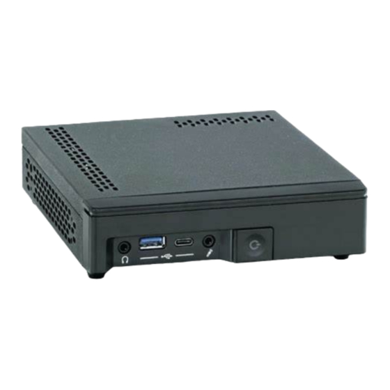
SBOX-5210 - User Guide, Rev. 1.0 4.2. Front I/O Panel Figure 1: Front I/O Panel 1 Power Button w/ LED (see Chapter 4.2.1) 2 Line-out (see Chapter 4.2.2) 3 Mic-in (see Chapter 4.2.3) 4 USB 3.1 Type A (see Chapter 4.2.4) 5 USB 3.1 Type C (see Chapter 4.2.4) 4.2.1. -
Page 22: Mic-In
SBOX-5210 - User Guide, Rev. 1.0 4.2.3. Mic-In The microphone jack is designed to connect the microphone used for video conferencing, voice narrations, or simple audio recordings. 4.2.4. USB 3.1 The front I/O panel of the SBOX-5210 provides two USB 3.1 / 2.0 interfaces. One is of Type A and the other is of Type C. These connectors allow connection of USB-compatible devices to the system. -
Page 23: Rear I/O Panel
SBOX-5210 - User Guide, Rev. 1.0 4.3. Rear I/O Panel Figure 2: Rear I/O Panel 1 DC-In (see Chapter 4.3.1) 2 DP (see Chapter 4.3.2) 3 HDMI (see Chapter 4.3.3) 4 GbE LAN (see Chapter 4.3.4) 5 USB 3.1 (see Chapter 4.3.5) 6 USB 2.0 (see Chapter 4.3.6) 4.3.1. -
Page 24: Usb 3.1
SBOX-5210 - User Guide, Rev. 1.0 Figure 3: Ethernet LED Status LED status: LED status: Off - Link is down Orange - 1000 Mbit/s link established Flashing Green - Link is up and active Green - 100 Mbit/s link established Steady Green - Link is up, no activity Off - 10 Mbit/s link established 4.3.5. -
Page 25: Right-Side I/O Panel
SBOX-5210 - User Guide, Rev. 1.0 4.4. Right-side I/O Panel Figure 4: Right-side I/O Panel 1 Kensington Security Slot (see Chapter 4.4.1) 4.4.1. Kensington Security Slot The slot is used for attaching a lock-and-cable apparatus. Locks are generally secured in place with a key or combination lock attached to a rubberized metal cable. -
Page 26: Internal View - - Top Side
SBOX-5210 - User Guide, Rev. 1.0 4.5. Internal View -- - Top Side Figure 5: Internal View -- - Top Side (without cover) 1 DDR4 SO-DIMM Memory Socket (see Chapter 4.4.1) 2 SATA Data Connector (see Chapter 4.4.2) 3 Hard Drive Power Connector (see Chapter 4.4.2) 4 SATA Data + Power Combo Cable (see Chapter 4.4.2) 5 SATA Data + Power Combo Connector (see Chapter 4.4.2) 6 SATA Data Plug (see Chapter 4.4.2) -
Page 27: Ddr4 So-Dimm Memory Socket
SBOX-5210 - User Guide, Rev. 1.0 4.5.1. DDR4 SO-DIMM Memory Socket The SBOX-5210 provides two 260-pin DDR4 SO-DIMM sockets (Figure 5, pos. 1) to install memory RAMs. 4.5.2. SATA Data + Power Combo Cable Connector The SBOX-5210 provides one 7+15-pin SATA data + power combo cable (Figure 5, pos. 4) for installing a 2.5" SATA HDD / SSD. -
Page 28: 5/ Accessing Internal Components
SBOX-5210 - User Guide, Rev. 1.0 5/ Accessing Internal Components This section contains important information that you must read before accessing the internal components. You must follow these procedures properly when installing, removing or handling any board. It is recommended to expand your system with applicable expansion card(s) before it is installed into an equipment, machine or cabinet. -
Page 29: Opening And Closing The Chassis
SBOX-5210 - User Guide, Rev. 1.0 5.1. Opening and Closing the Chassis The SBOX-5210 is factory configured to meet customer requirements. Kontron does not recommend opening the system as this may cause damage to internal components. Before opening the SBOX-5210, the system must be switched off and disconnected from the main power supply. -
Page 30: Installing So-Dimm Memory Module(S)
SBOX-5210 - User Guide, Rev. 1.0 6. Lift the top access cover up. 7. Loosen and remove the Phillips screws (four pieces), that secure the hard disk tray to the baseboard. Retain the screws for later use. Figure 8: Descrewing the hard disk tray 1 Screw hole to secure 2.5‘‘... -
Page 31: Installing A Hdd / Ssd
SBOX-5210 - User Guide, Rev. 1.0 Visually check that each lever latch is fully closed and correctly engaged with the notch on the memory module edge. 6. Repeat step 2 - 5 to install the second SO-DIMM memory module in case two DIMM memory modules are required. Use memory modules with the same memory density in both socket! In case two memory modules are installed, install the module to the lower socket first. - Page 32 SBOX-5210 - User Guide, Rev. 1.0 www.kontron.com // 32...
-
Page 33: 6/ Thermal Considerations
SBOX-5210 - User Guide, Rev. 1.0 6/ Thermal Considerations 6.1. Available Processors Please refer to the chapter 10/ "Technical Specifications". The list of processors may be extended over the product lifetime. 6.2. Convection Cooling The applied cooling method provides adequate cooling of the device during operation and performs a one-way thermal transfer to the airflow. - Page 34 SBOX-5210 - User Guide, Rev. 1.0 When the SBOX-5210 is extended and configured with third party components like M.2 expansion card and hard drives (HDD or SSD), it has to be taken into account that the air temperature inside the system is higher than the ambient temperature.
-
Page 35: 7/ Installation Instructions
The SBOX-5210 has to be installed and operated only by trained and qualified personnel. Only personnel with appropriate qualifications, trainings and authorization are permitted to install and work with the Kontron SBOX-5210. This device shall only be installed in or connected to systems that fulfill all necessary technical and specific environmental requirements. -
Page 36: System Mounting
SBOX-5210 - User Guide, Rev. 1.0 7.1. System Mounting In order to adapt the SBOX-5210 for mounting Kontron offers different mounting solutions such as: SBOX-5210 configuration with rubber feet for horizontal installation on the desktop as desktop unit SBOX-5210 configuration with a desk stand kit for vertical installation on the desktop as desktop unit ... -
Page 37: Desktop Installation - - Vertical
SBOX-5210 - User Guide, Rev. 1.0 7.1.2. Desktop Installation -- - Vertical SBOX-5210 is supplied with a chassis desk stand (Figure 11, pos. 1) as well as two screws (Figure 11, pos. 2). Figure 11: Chassis desk stand 1 Chassis Desk Stand 2 Screw To install the SBOX-5210 please proceed according to the steps described: 1. -
Page 38: Wall Mounting
SBOX-5210 - User Guide, Rev. 1.0 7.1.3. Wall Mounting Depending on the ordered SBOX-5210 configuration, your system may be supplied with a wall mount kit (Figure 13). The kit consists of two wall mount brackets (Figure 13, pos. 1) and four screws (Figure 13, pos. 2) Figure 13: Wall mount kit 1 Wall Mount Bracket 2 Screw... -
Page 39: Figure 15: Aligning The Holes Of Wall Mount Brackets And Chassis
SBOX-5210 - User Guide, Rev. 1.0 2. Align the screw holes on the wall mount brackets (Figure 13, pos. 1) with the holes on the chassis. Figure 15: Aligning the holes of wall mount brackets and chassis 3. Place the wall mount stand brackets on the chassis. 4. -
Page 40: Vesa Mounting
SBOX-5210 - User Guide, Rev. 1.0 7.1.4. VESA Mounting Depending on the ordered SBOX-5210 configuration, your system may be supplied with a VESA mounting kit (Figure 16). The kit consists of one VESA adapter (Figure 16, pos. 1), four cross-head screws (Figure 16, pos. 2) and four thumb head screws with hanger knobs (Figure 16, pos. -
Page 41: Figure 18: Securing The Thumb Screws
SBOX-5210 - User Guide, Rev. 1.0 To mount the SBOX-5210 please proceed according to the steps described: 1. Prepare the mounting surface with supplied thumb screws (Figure 16, pos. 3) and if necessary anchors corresponding to the mounting surface type if no VESA-compliant screw holes are available. 2. -
Page 42: Figure 20: Hanging The Sbox-5210 On The Mounting Surface
SBOX-5210 - User Guide, Rev. 1.0 Figure 20: Hanging the SBOX-5210 on the mounting surface 7. Now the SBOX-5210 is firmly hanged on the mounting surface. For a sufficient air circulation around the device, we recommend keep a proper clearance and not mount / operate any other devices within the clearance around the SBOX-5210. -
Page 43: Dc Power Connection
SBOX-5210 - User Guide, Rev. 1.0 7.2. DC Power Connection The SBOX-5210 is connected by a DC power input jack (Figure 2, pos. 1) to a DC power source. The SBOX-5210 is delivered with a power adapter to convert AC voltage into DC 19 V and a power cord to carry AC power to the power adapter. -
Page 44: 8/ Start Up
SBOX-5210 - User Guide, Rev. 1.0 8/ Start Up The SBOX-5210 must be only operated with the nominal voltage of 19 V DC of type SELV. For details refer to the chapter 10/ ‘‘Technical Specifications’’. 8.1. Connecting to DC Power Supply The DC power input jack (Figure 2, pos. -
Page 45: Operating System And Hardware Component Drivers
SBOX-5210 - User Guide, Rev. 1.0 8.2. Operating System and Hardware Component Drivers Your system can be supplied optionally with a pre-installed operating system. If you have ordered your SBOX-5210 with a pre-installed operating system, all drivers are installed in accordance with the system configuration ordered (optional hardware components). -
Page 46: 9/ Maintenance And Cleaning
SBOX-5210 - User Guide, Rev. 1.0 9/ Maintenance and Cleaning Equipment from Kontron requires only minimum servicing and maintenance for proper operation. For light soiling, clean the SBOX-5210 with a dry cloth. Carefully remove dust from the surface of the chassis using a clean, soft brush. -
Page 47: Technical Specifications
SBOX-5210 - User Guide, Rev. 1.0 Technical Specifications Table 2: Technical Specifications System Processor 9th / 8th Gen Intel® Core™ S-Series Processors (FCLGA1151, up to 35 W TDP) Intel® Pentium® G5000 Series Processors (FCLGA1151, up to 35 W TDP) ... -
Page 48: Mechanical Specifications
SBOX-5210 - User Guide, Rev. 1.0 System Software OS Support Windows 10 Linux (64 bit) 10.1. Mechanical Specifications Table 3: Mechanical Specifications Construction Metal Chassis with Plastic Front I/O Panel Dimensions (W x D x H) 36 mm x 165 mm x 147 mm / 1.42" x 6.50" x 5.79" ... -
Page 49: Environmental Conditions
SBOX-5210 - User Guide, Rev. 1.0 10.2. Environmental Conditions Table 4: Environmental Conditions Operating Temperature 0 °C ~ 40 °C / 32 °F ~ 104 °F Storage Temperature -20 °C ~ 80 °C / -4 °F ~ 176 °F Humidity ... -
Page 50: 11/ Standard Interfaces
SBOX-5210 - User Guide, Rev. 1.0 11/ Standard Interfaces -- - Pin Assignments Low-active signals are indicated by a minus sign. 11.1. DC Power Input Table 6: DC Power Input (see Figure 2, pos. 1) Signal Name DC Jack (female) +19V DC 11.2. -
Page 51: Usb 3.1 Port - - Type C
SBOX-5210 - User Guide, Rev. 1.0 11.3. USB 3.1 Port -- - Type C Table 8: USB 3.1 Port -- - Type C (see Figure 1, pos. 5) Signal Name 24-pin USB Connector Type A Version 3.1 / 2.0 USB3_TX1+ USB3_TX1- VCC AUX Config. -
Page 52: Usb 2.0 Port
SBOX-5210 - User Guide, Rev. 1.0 11.5. USB 2.0 Port Table 10: USB 2.0 Port (Figure 2, pos. 6) Signal Name 4-pin USB Connector Type A Version 2.0 Data- Data+ 11.6. DP Connector Table 11: DP Connector (see Figure 2, pos. 2) Signal Name DP Connector Link0+... -
Page 53: Hdmi Connector
SBOX-5210 - User Guide, Rev. 1.0 11.7. HDMI Connector Table 12: HDMI Connector (see Figure 2, pos. 3) Signal Name HDMI Connector Type A Version 1.4 TMDS Data2+ TMDS Data2- TMDS Data1+ TMDS Data1- TMDS Data0+ TMDS Data0- TMDS Clock+ TMDS Clock- DDC Clock DDC Data... -
Page 54: 12/ Bios
SBOX-5210 - User Guide, Rev. 1.0 BIOS 12.1. Starting the uEFI BIOS The SBOX-5210 is provided with a Kontron-customized, pre-installed and configured version of AMI Aptio® V uEFI BIOS. AMI BIOS firmware is based on the Unified Extensible Firmware Interface (UEFI) specification and the Intel® Platform Innovation Framework for EFI. -
Page 55: Starting The Uefi Bios
SBOX-5210 - User Guide, Rev. 1.0 12.2. Starting the uEFI BIOS The Setup utility features shows seven menus in the selection bar at the top of the screen: Main Advanced Security Power Event Logs Boot ... -
Page 56: Figure 22: Bios Main Menu Screen System Data And Time
SBOX-5210 - User Guide, Rev. 1.0 Figure 22: BIOS Main Menu Screen System Data and Time BIOS SETUP UTILITY Main Advanced Security Power Event Logs Boot Save & Exit BIOS Information BIOS Vendor American Megatrends Customized by Fujitsu Compliancy UEFI 2.7; PI 1.6 >... -
Page 57: Figure 23: Bios Main Menu Screen - - System Information
SBOX-5210 - User Guide, Rev. 1.0 Figure 23: BIOS Main Menu Screen -- - System Information BIOS SETUP UTILITY Main Advanced Security Power Event Logs Boot Save & Exit System Information Board & Firmware Details BIOS Revision R1.21.0 Build Date and Time 07/05/2019 12:28:49 Board D3654-B12... -
Page 58: Figure 24: Bios Main Menu Screen - - System Information
SBOX-5210 - User Guide, Rev. 1.0 Figure 24: BIOS Main Menu Screen -- - System Information BIOS SETUP UTILITY Main Advanced Security Power Event Logs Boot Save & Exit Open Source Software License Information This system board contains Open Source Software. →... -
Page 59: Advanced Setup Menu
SBOX-5210 - User Guide, Rev. 1.0 12.2.2. Advanced Setup Menu The Advanced setup menu provides sub-screens and functions for advanced configurations. The following sub- screen functions are included in the menu: Onboard Devices Configuration Auto BIOS Update CPU Configuration ... -
Page 60: Figure 25: Bios Advanced Menu
SBOX-5210 - User Guide, Rev. 1.0 Figure 25: BIOS Advanced Menu BIOS SETUP UTILITY Main Advanced Security Power Event Logs Boot Save & Exit Advanced Erase Disk [Disabled] > Onboard Devices Configuration > Auto BIOS Update > CPU Configuration > Drive Configuration >... -
Page 61: Figure 26: Bios Advanced Menu - - Onboard Devices Configuration
SBOX-5210 - User Guide, Rev. 1.0 Figure 26: BIOS Advanced Menu -- - Onboard Devices Configuration BIOS SETUP UTILITY Main Advanced Security Power Event Logs Boot Save & Exit Onboard Device Configuration LAN1 Configuration [Enabled] → ←: Select Screen ↑ ↓: Select Item Audio Configuration Enter: Select Azalia HD Audio... -
Page 62: Figure 27: Bios Advanced Menu - - Auto Bios Update
SBOX-5210 - User Guide, Rev. 1.0 Figure 27: BIOS Advanced Menu -- - Auto BIOS Update BIOS SETUP UTILITY Main Advanced Security Power Event Logs Boot Save & Exit Auto BIOS Update Terms of use [Decline] → ←: Select Screen Automatic BIOS update [Disabled] ↑... -
Page 63: Figure 28: Bios Advanced Menu - - Cpu Configuration
SBOX-5210 - User Guide, Rev. 1.0 Figure 28: BIOS Advanced Menu -- - CPU Configuration BIOS SETUP UTILITY Main Advanced Security Power Event Logs Boot Save & Exit CPU Configuration Hyper-Threading [Enabled] Active Processor Cores [All] → ←: Select Screen Intel Virtualization Technology [Enabled] ↑... -
Page 64: Figure 29: Bios Advanced Menu - - Drive Configuration
SBOX-5210 - User Guide, Rev. 1.0 Figure 29: BIOS Advanced Menu -- - Drive Configuration BIOS SETUP UTILITY Main Advanced Security Power Event Logs Boot Save & Exit Drive Configuration OffBoard Controller Configuration → ←: Select Screen No controller present ↑... -
Page 65: Figure 30: Bios Advanced Menu - - Smart Setting
SBOX-5210 - User Guide, Rev. 1.0 Figure 30: BIOS Advanced Menu -- - SMART Setting BIOS SETUP UTILITY Main Advanced Security Power Event Logs Boot Save & Exit SMART Settings SMART Self Test [Enabled] → ←: Select Screen ↑ ↓: Select Item Enter: Select +/-: Change Opt. -
Page 66: Figure 31: Bios Advanced Menu - - Trusted Computing
SBOX-5210 - User Guide, Rev. 1.0 Figure 31: BIOS Advanced Menu -- - Trusted Computing BIOS SETUP UTILITY Main Advanced Security Power Event Logs Boot Save & Exit Trusted Computing TPM Support [Enabled] → ←: Select Screen Pending TPM operation* [None] ↑... -
Page 67: Figure 32: Bios Advanced Menu - - Usb Configuration
SBOX-5210 - User Guide, Rev. 1.0 Figure 32: BIOS Advanced Menu -- - USB Configuration BIOS SETUP UTILITY Main Advanced Security Power Event Logs Boot Save & Exit USB Configuration USB Devices: → ←: Select Screen 1 Keyboard ↑ ↓: Select Item Enter: Select >... -
Page 68: Figure 33: Bios Advanced Menu - - Usb Configuration - - Usb Port Security
SBOX-5210 - User Guide, Rev. 1.0 Figure 33: BIOS Advanced Menu -- - USB Configuration -- - USB Port Security BIOS SETUP UTILITY Main Advanced Security Power Event Logs Boot Save & Exit USB Port Control [Enable all ports] USB Device Control* [Enable all devices] →... -
Page 69: Figure 34: Bios Advanced Menu - - System Management
SBOX-5210 - User Guide, Rev. 1.0 Figure 34: BIOS Advanced Menu -- - System Management BIOS SETUP UTILITY Main Advanced Security Power Event Logs Boot Save & Exit System Management Fan startup check [Disabled] Fan Control [Enhanced] Watchdog Timeout Temperatures 48 °C / 118 °F Ambient 36 °C / 96 °F... -
Page 70: Figure 35: Bios Advanced Menu - - Amt Configuration
SBOX-5210 - User Guide, Rev. 1.0 Figure 35: BIOS Advanced Menu -- - AMT Configuration BIOS SETUP UTILITY Main Advanced Security Power Event Logs Boot Save & Exit AMT Configuration ME Version 12.0.35.1427 → ←: Select Screen ↑ ↓: Select Item Enter: Select +/-: Change Opt. -
Page 71: Figure 36: Bios Advanced Menu - - Network Stack Configuration
SBOX-5210 - User Guide, Rev. 1.0 Figure 36: BIOS Advanced Menu -- - Network Stack Configuration BIOS SETUP UTILITY Main Advanced Security Power Event Logs Boot Save & Exit Network Stack Configuration Network Stack [Disabled] → ←: Select Screen Ipv4 PXE Support* [Enabled] ↑... -
Page 72: Figure 37: Bios Advanced Menu - - Graphic Configuration
SBOX-5210 - User Guide, Rev. 1.0 Figure 37: BIOS Advanced Menu -- - Graphic Configuration BIOS SETUP UTILITY Main Advanced Security Power Event Logs Boot Save & Exit Graphic Configuration Primary Display [Auto] → ←: Select Screen Internal Graphics [Auto] ↑... -
Page 73: Figure 38: Bios Advanced Menu - - Realtek Pcie Gbe Family Controller (Mac:4C:52:62:Bc:a5:94)
SBOX-5210 - User Guide, Rev. 1.0 Figure 38: BIOS Advanced Menu -- - Realtek PCIe GBE Family Controller (MAC:4C:52:62:BC:A5:94) BIOS SETUP UTILITY Main Advanced Security Power Event Logs Boot Save & Exit Driver Information Driver Name: Realtek UEFI UNDI Driver Driver Version: 2.040 Driver Released Date:... -
Page 74: Security Setup Menu
SBOX-5210 - User Guide, Rev. 1.0 12.2.3. Security Setup Menu The Security setup menu provides information about the passwords and functions for specifying the security settings. The passwords are case-sensitive. The SBOX-5210 provides no factory-set passwords. If there is already a password installed, the system asks for this first. To clear a password, simply enter nothing and acknowledge by pressing <RETURN>. - Page 75 SBOX-5210 - User Guide, Rev. 1.0 Feature Option Description System Firmware [Disabled], Changing the System Firmware version is only possible if Update [Restricted], [Enabled] ENABLED or RESTRICTED. [Enabled]: Windows Update (WU) and FUJITSU tools can change / update the System firmware version. [Restricted]: only FUJITSU tools can change / update the System firmware version.
-
Page 76: Figure 40: Bios Security Setup Menu - - Secure Boot Configuration
SBOX-5210 - User Guide, Rev. 1.0 Figure 40: BIOS Security Setup Menu -- - Secure Boot Configuration BIOS SETUP UTILITY Main Advanced Security Power Event Logs Boot Save & Exit Secure Boot Configuration Platform Mode User → ←: Select Screen Secure Boot Not Active ↑... -
Page 77: Figure 41: Bios Security Setup Menu - - Secure Boot Configuration - - Key Management
SBOX-5210 - User Guide, Rev. 1.0 Figure 41: BIOS Security Setup Menu -- - Secure Boot Configuration -- - Key Management BIOS SETUP UTILITY Main Advanced Security Power Event Logs Boot Save & Exit Factory Default Key Provision [Enabled] > Enroll all Factory Default keys >... - Page 78 SBOX-5210 - User Guide, Rev. 1.0 Feature Option Description Authorized [Set New Key], TimeStamps [Append Key] OsRecovery [Set New Key], Signatures [Append Key] www.kontron.com // 78...
- Page 79 SBOX-5210 - User Guide, Rev. 1.0 12.2.3.1. Remember the password It is highly recommended to keep a record of all passwords in a safe place. Forgotten passwords results in being locked out of the system. If the system cannot be booted because the User Password or the Supervisor Password are not know, contact Kontron Support for further assistance.
-
Page 80: Power Setup Menu
SBOX-5210 - User Guide, Rev. 1.0 12.2.4. Power Setup Menu The Power setup menu provides functions for power configurations. Figure 42: BIOS Power Setup Menu BIOS SETUP UTILITY Main Advanced Security Power Event Logs Boot Save & Exit Power Settings Power Failure Recovery [Always On] Never Off... - Page 81 SBOX-5210 - User Guide, Rev. 1.0 This item appears only when selecting ’Monthly‘ for Wake Up Mode. *** This item appears only when enbaling CPU TDP Limit Feature Option Description Power Failure [Disabled], [Always After recovery from power failure: Recovery Off], [Always On], [Disabled]: Remain Off.
-
Page 82: Event Logs Setup Menu
SBOX-5210 - User Guide, Rev. 1.0 12.2.5. Event Logs Setup Menu The Event Logs setup menu lists the event log settings and options. The following sub-screen functions are included in the menu: Change Smbios Event Log Settings View Smbios Event Log Figure 43: BIOS Event Logs Setup Menu BIOS SETUP UTILITY Main... -
Page 83: Figure 44: Bios Event Logs Setup Menu - - Change Smbios Event Log Settings
SBOX-5210 - User Guide, Rev. 1.0 Figure 44: BIOS Event Logs Setup Menu -- - Change Smbios Event Log Settings BIOS SETUP UTILITY Main Advanced Security Power Event Logs Boot Save & Exit Smbios Event Log Smbios Event Log [Enabled] →... -
Page 84: Boot Setup Menu
SBOX-5210 - User Guide, Rev. 1.0 12.2.6. Boot Setup Menu The boot setup menu lists the for boot device priority order, that is generated dynamically. Figure 46: BIOS Boot Setup Menu BIOS SETUP UTILITY Main Advanced Security Power Event Logs Boot Save &... - Page 85 SBOX-5210 - User Guide, Rev. 1.0 Feature Option Description Boot Removable [Disabled], [Enabled] This option enables / disables support for booting to removable Media devices, such as USB flash drives. www.kontron.com // 85...
-
Page 86: Save & Exit Setup Menu
SBOX-5210 - User Guide, Rev. 1.0 12.2.7. Save & Exit Setup Menu The exit setup menu provides functions for handling changes made to the UEFI BIOS settings and the exiting of the setup program. Figure 47: BIOS Save & Exit Setup Menu BIOS SETUP UTILITY Main Advanced... -
Page 87: Appendix A: List Of Acronyms
SBOX-5210 - User Guide, Rev. 1.0 Appendix A: List of Acronyms The following table does not contain the complete acronyms used in signal names, signal type definitions or similar. A description of the signals is included in the I/O Connector and Internal connector chapters within this user guide. Table 17: List of Acronyms Two-Dimensional Real-Time Clock... -
Page 88: About Kontron
SBOX-5210 - - User Guide, Rev. 1.0 About Kontron Kontron is a global leader in Embedded Computing Technology (ECT). As a part of technology group S&T, Kontron offers a combined portfolio of secure hardware, middleware and services for Internet of Things (IoT) and Industry 4.0 applications.
Need help?
Do you have a question about the Kontron SBOX-5210 and is the answer not in the manual?
Questions and answers