
Related Manuals for S&T Kontron KBox B-201


Summary of Contents for S&T Kontron KBox B-201
- Page 1 USER GUIDE KBox B-201 Doc. User Guide, Rev. 1.3 Doc. ID: 1062-7377 www.kontron.com // 1...
- Page 2 KBox B-201 - User Guide, Rev. 1.3 This page has been intentionally left blank www.kontron.com // 2...
- Page 3 KBox B-201 - User Guide, Rev. 1.3 KBOX B-201 - USER GUIDE Disclaimer Kontron would like to point out that the information contained in this user guide may be subject to alteration, particularly as a result of the constant upgrading of Kontron products. This document does not entail any guarantee on the part of Kontron with respect to technical processes described in the user guide or any product characteristics set out in the user guide.
- Page 4 KBox B-201 - User Guide, Rev. 1.3 Intended Use This embedded Box PC, sold by Kontron, is part of Kontron’s B-Series intended for high performance, small form- factor needs with long-term availability. The product can operate in a temperature range from 0°C to plus 45°C; the storage elements can withstand temperatures from minus 20°C to plus 80°C, and a humidity of 10 to 93 percent does not affect the function of the product.
- Page 5 KBox B-201 - User Guide, Rev. 1.3 Revision History Revision Brief Description of Changes Date of Issue Author/ Editor Initial version 2018-Aug-16 Changed Figure 24 2018-Dec-03 FCC Information changed and additional BIOS 2019-Mar-20 information for updates. Installing SSD push in flat new intended use and 2020-Feb-18 new block diagram Terms and Conditions...
-
Page 6: Symbols
KBox B-201 - User Guide, Rev. 1.3 Symbols The following symbols may be used in this user guide DANGER indicates a hazardous situation which, if not avoided, will result in death or serious injury. WARNING indicates a hazardous situation which, if not avoided, could result in death or serious injury. -
Page 7: For Your Safety
KBox B-201 – User Guide, Rev. 1.3 For Your Safety Your new Kontron product was developed and tested carefully to provide all features necessary to ensure its compliance with electrical safety requirements. It was also designed for a long fault-free life. However, the life expectancy of your product can be drastically reduced by improper treatment during unpacking and installation. -
Page 8: Lithium Battery Precautions
KBox B-201 - User Guide, Rev. 1.3 Lithium Battery Precautions If your product is equipped with a lithium battery, take the following precautions when replacing the battery. Danger of explosion if the battery is replaced incorrectly. Replace only with same or equivalent battery type recommended by the manufacturer. ... -
Page 9: Table Of Contents
KBox B-201 - User Guide, Rev. 1.3 Table of Contents Symbols ..........................................6 For Your Safety ........................................7 High Voltage Safety Instructions .................................. 7 Special Handling and Unpacking Instruction ............................7 Lithium Battery Precautions ..................................8 General Instructions on Usage ..................................8 Quality and Environmental Management .............................. - Page 10 KBox B-201 - User Guide, Rev. 1.3 8.3. Mounting Brackets (Option) ................................37 8.3.1. Mount Options ....................................... 39 8.4. VESA 100 Mount Assembly (Option) ..............................40 8.4.1. Mount Options ....................................... 42 Starting Up......................................44 9.1. Connecting to DC Power Supply ................................44 9.2.
-
Page 11: List Of Tables
KBox B-201 - User Guide, Rev. 1.3 List of Tables Table 1: Scope of Delivery ....................................17 Table 2: Accessories ......................................17 Table 3: Mainboard Specification ................................47 Table 4: Processor Specification ................................47 Table 5: Memory Specification ..................................47 Table 6: Storage Specification .................................. - Page 12 KBox B-201 - User Guide, Rev. 1.3 Figure 24: Mounting Brackets Desktop Mount Options ........................39 Figure 25: Mounting Brackets Wall Mount Options ..........................39 Figure 26: VESA Mounting Assembly Kit ..............................40 Figure 27: KBox B-201 Mounting Position ............................... 40 Figure 28: Inserting the Band ..................................
-
Page 13: 1/ General Safety Instructions For It Equipment
KBox B-201 - User Guide, Rev. 1.3 1/ General Safety Instructions for IT Equipment Read this chapter carefully and take careful note of the instructions, which have been compiled for your safety and to ensure to apply in accordance with intended regulations. If the following general safety instructions are not observed, it could lead to injuries to the operator and/or damage of the product;... - Page 14 KBox B-201 - User Guide, Rev. 1.3 Additional safety instructions for DC power supply circuits To guarantee safe operation of products with DC power supply voltages larger than 60 volts DC or a power consumption larger than 120 VA, please observe that: ...
- Page 15 KBox B-201 - User Guide, Rev. 1.3 1.2. Instructions for the Lithium Battery The KBox B-201’s mainboard is equipped with a lithium battery. When replacing the battery please observe the instructions described in Chapter 14.3.1: Replacing Lithium Battery. Danger of explosion when replacing with wrong type of battery. Replace only with the same or equivalent type recommended by the manufacturer.
-
Page 16: 2/ Introduction
KBox B-201 - User Guide, Rev. 1.3 2/ Introduction This user guide describes the KBox B-201 made by Kontron and focuses on describing the KBox B-201’s special features. New users are recommended to study the installation instructions within this user guide before switching on the power. -
Page 17: 3/ Scope Of Delivery
KBox B-201 - User Guide, Rev. 1.3 3/ Scope of Delivery Check that your delivery is complete, and contains the items below. If you discover damaged or missing items, contact your dealer. Table 1: Scope of Delivery Part Qty. Part Description KBox B-201 High performance PC box with mITX mainboard AC power supply... -
Page 18: 4/ Product Overview
KBox B-201 - User Guide, Rev. 1.3 4/ Product Overview Before working with the KBox B-201, Kontron recommends that users take a few minutes to learn about the various parts of the KBox B-201. The following chapter provides information regarding KBox B-201 features The KBox B-201 is a small form factor Box PC family designed for high performance needs with 6 Gen. -
Page 19: Front View
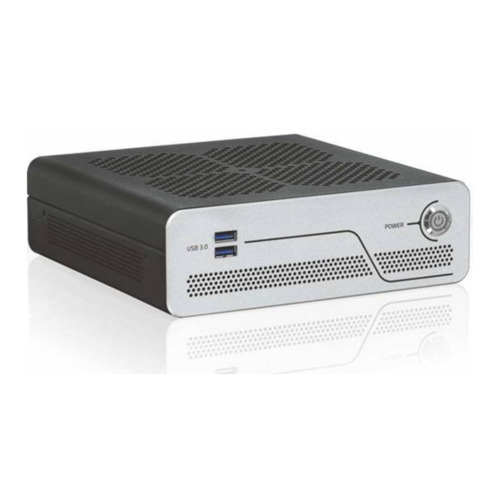
KBox B-201 - User Guide, Rev. 1.3 4.1. Front View The front side contains the power-on button, two additional USB 3.0 ports, and ventilation holes for air-output. Figure 4: Front View 2x USB 3.0 Power-on button with power LED Ventilation holes (air-output) 4.1.1. -
Page 20: Rear View
KBox B-201 - User Guide, Rev. 1.3 4.2. Rear View The rear panel contains the main I/O interfaces and includes the power in connector (DC IN), ventilation holes for air- output, and two fastening screws for the top cover. Figure 5: Rear View PS/2 Keyboard Serial Port Audio line-in... - Page 21 KBox B-201 - User Guide, Rev. 1.3 To avoid disturbances, it is recommended not to use any adapters such as DP/VGA, DP/DVI or DP/HDMI adapter at the DisplayPort connectors. The KBox B-201 supports up to three independent digital displays (2x DP + 1x DVI-D). 4.2.1.5.
-
Page 22: Left And Right Side Views
KBox B-201 - User Guide, Rev. 1.3 4.3. Left and Right Side Views The right and left sides contain ventilation holes for air-output. The two threaded screw holes available on both sides (Figure 6, pos. 2) are used to attach mounting brackets, see Chapter 8.3: Mounting Brackets (Option) or alternatively to attach the vertical stand, see Chapter 8.2: Vertical Stand (Option). -
Page 23: Top Cover And Bottom Views
KBox B-201 - User Guide, Rev. 1.3 4.4. Top Cover and Bottom Views The top cover consisting of a metal plate with ventilation holes for air-intake and a separate metal plate underneath with a circular opening above the internal fan. Figure 7: Top View Circular opening on metal plate Ventilation holes (air-intake) -
Page 24: 5/ System Extension
KBox B-201 - User Guide, Rev. 1.3 5/ System Extension 5.1. External Storage 5.1.1. 2.5” SSD Drive Bay The external 2.5” SSD drive bay uses the SATA interface (SATA III / SATA-600 compliant) for 512 GByte or 1 TByte 2.5” SSD memory expansion. 5.2. -
Page 25: 6/ Accessing Internal Components
KBox B-201 - User Guide, Rev. 1.3 6/ Accessing Internal Components This chapter contains important information that you must read before accessing internal components. Care must be taken to follow these procedures properly when accessing or installing internal components. It is recommended to expand your product with additional cards before mounting the product. -
Page 26: Figure 9: Top Cover Fastening Screws
KBox B-201 - User Guide, Rev. 1.3 To open the chassis, perform the following: Close all applications. Shut down the product properly and disconnect the power cable from the power source. Disconnect all peripherals. Place the KBox B-201 on a flat, clean and ESD-safe surface. Remove the two top cover screws on the rear panel (Figure 9) and retain the screws to close the top cover later. -
Page 27: Opening And Closing Ssd Drive Bay Cover
KBox B-201 - User Guide, Rev. 1.3 6.2. Opening and Closing SSD Drive Bay Cover Before opening the SSD drive bay cover pay attention to the safety instructions at the start of this chapter. Before installing a 2.5” SSD, observe the manufacturer’s instructions. To open the SSD drive bay cover, perform the following: Close all applications. -
Page 28: Installing And Removing External 2.5" Ssd
KBox B-201 - User Guide, Rev. 1.3 6.2.1. Installing and Removing External 2.5” SSD To install a 2.5” SSD, perform the following: Open the SDD drive bay cover by following the instructions in Chapter 6.2: Opening and Closing SSD Drive Bay Cover, steps 1 to 6. -
Page 29: Installing And Removing Internal M.2 Ssd Card
KBox B-201 - User Guide, Rev. 1.3 6.3. Installing and Removing Internal M.2 SSD Card To install an M.2 card, perform the following: Close all applications; shut down the product properly and disconnect the connection to the power source. Disconnect all peripherals Open the chassis as described in Chapter 6.1: Opening and Closing the Chassis, steps 1 to 5. -
Page 30: Installing And Removing Internal Mpcie Expansion Card
KBox B-201 - User Guide, Rev. 1.3 Secure the mSATA card by pressing down on the free end and carefully fasten the mSATA card to the mainboard with a mounting screw and spacer (if required) between the mSATA card and the mainboard. Do not use too much force when fastening the mSATA expansion card’s mounting screw. - Page 31 KBox B-201 - User Guide, Rev. 1.3 To remove a mPCIe card from the shared mSATA/mPCIE socket, proceed as follows: Close all applications; shut down the product properly and disconnect the power source. Disconnect all peripherals. Open the chassis as described in the Chapter 6.1: Opening and Closing the Chassis, steps 1 to 5. Locate the mPCIe card installed into your product.
-
Page 32: 7/ Thermal Considerations
KBox B-201 - User Guide, Rev. 1.3 7/ Thermal Considerations 7.1. Active Cooling The KBox B-201 is actively fan cooled. Air enters through the top cover’s ventilation holes (Figure 14, pos. 1) and the fan distributes the air over the mainboard before the air exits by the ventilation holes on the right, left, front and rear sides (Figure 15, pos. -
Page 33: Minimum System Clearance (Keep Out Area)
KBox B-201 - User Guide, Rev. 1.3 7.2. Minimum System Clearance (Keep out Area) To provide the maximum airflow through and around the box, a minimum distances to surrounding parts must be observed. Before installing, observe the thermal considerations mentioned in Chapter 8/ Installation Instructions, such as keep out areas and correct mount orientation (Figure 22 and Figure 23). -
Page 34: 8/ Installation Instructions
KBox B-201 - User Guide, Rev. 1.3 8/ Installation Instructions The KBox B-201 operates horizontally (upward orientation) and vertically when mounted on a desk, wall or the rear side of a monitor. The various mounting accessories are chassis feet (supplied in the delivery) and optionally vertical stand, wall mount brackets, and VESA 100 mount assembly. -
Page 35: Chassis Feet
KBox B-201 - User Guide, Rev. 1.3 Expansion cards and memory installation should be performed before Installation. 8.1. Chassis Feet To use the KBox B-201 on a desktop, install the supplied four self-adhesive chassis feet as follows: Ensure that the KBox B-201’s bottom surface is clean and free from dust and dirt. Remove the cover from the back of each of the self-adhesive chassis feet and carefully press the chassis feet onto the KBox B-201 (Figure 16). -
Page 36: Vertical Stand (Option)
KBox B-201 - User Guide, Rev. 1.3 8.2. Vertical Stand (Option) For desktop use, the KBox B-201 can be positioned vertically using a vertical stand, see Figure 18: Vertical Stand. Figure 18: Vertical Stand Vertical stand screw holes To mount the KBox B-201 on the vertical stand: Position the KBox B-201 with the chassis side on which the vertical stand is to be fastened facing upwards. -
Page 37: Mounting Brackets (Option)
KBox B-201 - User Guide, Rev. 1.3 8.3. Mounting Brackets (Option) To wall mount (vertically or horizontally) as shown in Figure 25, or fixed desktop (underneath or on top) of a desktop use the mounting brackets as shown in Figure 24. Each mounting bracket contains two sets of mounting holes to fasten to the KBox B-201. -
Page 38: Figure 22: Keep Out Areas - With Top Cover Facing The Mount Surface
KBox B-201 - User Guide, Rev. 1.3 Fasten the first mounting bracket to KBox B-201’s side using a torx (08 x 60) screwdriver. Attach the second mounting brackets on the opposite side, as in step 2 to 3. Use the wall mount’s key mounting holes Figure 21, (pos. 3), to mount on a wall or desktop while observing the specified clearance of 10 mm (keep out area) shown in Figure 22 and Figure 23. -
Page 39: Mount Options
KBox B-201 - User Guide, Rev. 1.3 8.3.1. Mount Options Figure 24: Mounting Brackets Desktop Mount Options Mounted (fixed) on a desktop Mounted (fixed) underneath a desktop Danger of Fire If mounted horizontally with the top cover facing downward, the KBox B 201 may overheat and hot substances may exit through the top cover’s ventilation holes causing a fire hazard. -
Page 40: Vesa 100 Mount Assembly (Option)
KBox B-201 - User Guide, Rev. 1.3 8.4. VESA 100 Mount Assembly (Option) The VESA mount assembly mounts the KBox B-201 and external PSU on the back of a monitor supporting VESA 100. Figure 26: VESA Mounting Assembly Kit The VESA 100 mount assembly kit contains: VESA 100 mounting frame Hook and loop band (length 40 mm, width 25 mm ) 4x screws (M4x 20 mm) -
Page 41: Figure 28: Inserting The Band
KBox B-201 - User Guide, Rev. 1.3 Figure 28: Inserting the Band Threading slots on the left and right PSU aligning brackets D-ring Double back with the flexible hook and loop band and feed the rough end through the band’s D-ring. Pull the band through the D-ring and press approximately 30 mm to 50 mm of the self-gripping sides together to form a loose loop. -
Page 42: Mount Options
KBox B-201 - User Guide, Rev. 1.3 8.4.1. Mount Options The VESA 100 mount assembly mounts either directly on the rear side of the monitor, see Chapter 8.4.1.1: Mounting on non VESA Mount Stand Monitor or on the rear side of the monitor using the monitors stand, see Chapter 8.4.1.2: Mounting on Monitor with VESA 100 Stand. -
Page 43: Figure 33: Vesa Monitor Stand Assembly
KBox B-201 - User Guide, Rev. 1.3 8.4.1.2. Mounting on Monitor with VESA 100 Stand Remove the monitor’s stand. Feed the supplied four supplied (M4x 20 mm) screws through the four mounting holes on the monitor’s stand and attach one of the supplied spacers to the screw’s free end (Figure 33). Figure 33: VESA Monitor Stand Assembly First insert the free end of the screw (with spacer) through the four mount hole on the VESA mount frame and then onto the VESA 100 mount hole on the back of the monitor. -
Page 44: 9/ Starting Up
KBox B-201 - User Guide, Rev. 1.3 9/ Starting Up The KBox B-201 comes hardware configured, and on request with a pre-installed Operating System (OS) and all the necessary drivers (in accordance with the ordered hardware configuration); enabling full operation when powered on for the first time. -
Page 45: Operating System (Os) And Hardware Component Drivers
KBox B-201 - User Guide, Rev. 1.3 9.3. Operating System (OS) and Hardware Component Drivers The KBox B-201 supports flexible software options with different Operating System (OS) and drivers support for factory configured hardware components. If ordered with a pre-installed OS and all appropriate drivers (in accordance with the ordered hardware configuration) the product is fully operational when powered on for the first time. -
Page 46: 10/ Technical Data
KBox B-201 - User Guide, Rev. 1.3 Technical Data 10.1. Block Diagram- KBox B-201 Figure 35: KBox B-201 System Block Diagram KBox B-201 2x DisplayPort Dual Channel 7th Den.Lntel® /ore™ DDR4-2400 DVI-D i3 /i5/i7 (up to 32 GB) 2x USB 3.0 2x LAN (GbE) Power on Front Panel... -
Page 47: Technical Specification
KBox B-201 - User Guide, Rev. 1.3 10.2. Technical Specification Table 3: Mainboard Specification Type/Product Name D3433-S2 Form factor Mini-ITX ( 170mm x 170 mm ) ( 6.7“ x 6.7“) Processor Gen. Intel® Core™ i3/i5/i7 Max. 65W TDP Chipset Intel® Q170 Memory DDR4 –... -
Page 48: Table 7: Interface Specifications
KBox B-201 - User Guide, Rev. 1.3 Table 7: Interface Specifications External Interfaces – Front side USB 3.0 2x USB 3.0 External Interfaces – Rear side USB 3.0 4x USB 3.0 USB 2.0 4x USB 2.0 Display Port 2x DP V 1.2 (Resolution: 4096 x 2304 @ 60 Hz Max.) DVI-D 1x DVI-D (Supports single link only) 2x LAN (GbE) -
Page 49: Mechanical Specification
KBox B-201 - User Guide, Rev. 1.3 10.3. Mechanical Specification The mechanical specification of the KBox B-201 and the possible mounting options is shown in Table 11: Mechanical Specification. Table 11: Mechanical Specifications KBox B-201 Dimensions Depth 190 mm (7.48”) Width 190 mm (7.48”) Height... -
Page 50: Figure 38: Dimensions Top Cover
KBox B-201 - User Guide, Rev. 1.3 6.5 mm Figure 38: Dimensions Top Cover 190 mm 190 mm Figure 39: Dimensions Bottom Side 190 mm 190 mm www.kontron.com // 50... -
Page 51: Dimension Diagrams- Wall Mount Brackets
KBox B-201 - User Guide, Rev. 1.3 Figure 40: Dimensions Right Side and Left Side 6.5 mm 6.5 mm 190 mm 190 mm 60 mm 10.3.2. Dimension Diagrams- Wall Mount Brackets The dimension drawing shows the main mounting bracket mechanical dimension. Figure 41: Dimensions with Mounting Brackets Ø... -
Page 52: Directives And Standards
KBox B-201 - User Guide, Rev. 1.3 10.5. Directives and Standards The KBox B-201 complies with the European Council Directive and the approximation of the laws of the member states. If modified, the prerequisites for specific approvals may no longer apply. Kontron is not responsible for any radio television interference caused by unauthorized modifications of the product or the substitution or attachment of connecting cables and equipment other than those specified by Kontron. -
Page 53: Power Specification
KBox B-201 - User Guide, Rev. 1.3 10.6. Power Specification The KBox B-201 has no internal power supply and is powered only via the supplied power supply Unit (PSU) connected to the + 12 V DC Jack (DC-IN) on the rear panel. The mainboard is supplied by +12 V DC and generates all other required voltages. -
Page 54: 11/ External Interface - Pin Assignments
KBox B-201 - User Guide, Rev. 1.3 11/ External Interface - Pin Assignments 11.1. DC IN Power Connector Pin Assignment The DC IN power connector is a barrel jack (5.5 mm/ 2.5 mm) with center pole and an input voltage of 12 V only. Table 16: DC power Jack Pin Assignment Signal Name Power Jack... -
Page 55: Usb 2.0 Connector Pin Assignment
KBox B-201 - User Guide, Rev. 1.3 11.3. USB 2.0 Connector Pin Assignment Table 18: USB 2.0 Connector Pin Assignment Signal Name 4-pin USB Connector Type A Version 2.0 +5 V (fused protected) Data- Data+ Low-active signals are indicated by a minus sign. 11.4. -
Page 56: Display Port (Dp) V1.2 Connector Pin Assignment
KBox B-201 - User Guide, Rev. 1.3 11.5. Display Port (DP) V1.2 Connector Pin Assignment Table 21: Display Port (DP) Connector Pin Assignment Signal Name Display Port Connector Signal Name Link0+ Link0- Link1+ Link1- Link2+ Link2- Link3+ Link3- DVI dongle detect AUX+ AUX- Hot Plug detect... -
Page 57: Ps/2 Keyboard Connector Pin Assignment
KBox B-201 - User Guide, Rev. 1.3 11.7. PS/2 Keyboard Connector Pin Assignment Table 23: PS/2 Keyboard Connector Pin Assignment Signal Name PS/2 Keyboard Connector Data +5V (fuse protected) Clock Keyboard_On ( low asserted pulse) 11.8. PS/2 Mouse Connector Pin Assignment Table 24: PS/2 Mouse Connector Pin Assignment Signal Name PS/2 Mouse Connector... -
Page 58: Serial Port Connector Pin Assignment
KBox B-201 - User Guide, Rev. 1.3 11.10. Serial Port Connector Pin Assignment Table 26: Serial Interface COM1 port (RS232) Connector Pin Assignment Signal Name- RS232 9-pin D-SUB Connector (Data Carrier Detect) (Signal In) SOUT (Signal out)) (Data Terminal Ready) (Data Set Ready) (Request to Send) (Clear to Send) -
Page 59: 12/ Bios
KBox B-201 - User Guide, Rev. 1.3 BIOS The KBox B-201 uses the AMI Aptio 5.x (UEFI) BIOS supported by the D3433-S2 mainboard. The uEFI BIOS features a variety of enhanced functions specifically tailored to the KBox B-201’s hardware features: ... -
Page 60: Bios Update
KBox B-201 - User Guide, Rev. 1.3 Sub-screen Description <ESC> <ESC> key exits a major Setup menu and enters the Exit Setup menu Pressing the <ESC> key in a sub-menu displays the next higher menu level <RETURN> <RETURN> key executes a command or selects a submenu 12.2. -
Page 61: 13/ Technical Support
KBox B-201 - User Guide, Rev. 1.3 Technical Support In order to request technical support, please send an email with the information below to support@kontron.com Product name Product model number Serial number of the unit Brief problem description ... -
Page 62: 14/ Storage, Transportation And Maintenance
KBox B-201 - User Guide, Rev. 1.3 Storage, Transportation and Maintenance 14.1. Storage If the product is not in use for an extended period time, disconnect the power plug from the mains power source .If it is necessary to store the product then re-pack the product as originally delivered to avoid damage. The storage facility must meet the products environmental storage requirements as stated within this user guide. -
Page 63: 15/ Warranty
KBox B-201 - User Guide, Rev. 1.3 Warranty Kontron defines product warranty in accordance with regional warranty definitions. Claims are at Kontron’s discretion and limited to the defect being of a material nature. To find out more about the warranty conditions and the defined warranty period for your region, following the steps below: Visit Kontron’s Term and Conditions webpage. -
Page 64: Appendix A: List Of Acronyms
KBox B-201 - User Guide, Rev. 1.3 Appendix A: List of Acronyms Table 28: List of Acronyms (Example) Application Programming Interface Random Access memory BIOS REACH Basic Input Output System Registration, Evaluation, Authorization and restriction of Chemicals Communication port Return of Material Authorization Direct Current+ ROHS Restriction Of Hazardous Substances... -
Page 65: About Kontron
KBox B-201 – User Guide, Rev. 1.3 About Kontron Kontron is a global leader in embedded computing technology (ECT). As a part of technology group S&T, Kontron offers a combined portfolio of secure hardware, middleware and services for Internet of Things (IoT) and Industry 4.0 applications.
Need help?
Do you have a question about the Kontron KBox B-201 and is the answer not in the manual?
Questions and answers