
Subscribe to Our Youtube Channel
Related Manuals for S&T kontron KBox C-103-CFL Series


Summary of Contents for S&T kontron KBox C-103-CFL Series
- Page 1 USER GUIDE KBox C-103-CFL-4 KBox C-103-CFL-2 KBox C-103-CFL-1 KBox C-103-CFL-0 KBox C-103-CFL-x User Guide, Rev. 1.0 Doc. ID: 1067-5219 www.kontron.com // 1...
- Page 2 KBox C-103-CFL-x - User Guide, Rev. 1.0 This page has been intentionally left blank www.kontron.com // 2...
- Page 3 KBox C-103-CFL-x - User Guide, Rev. 1.0 KBOX C-103-CFL-X - USER GUIDE Disclaimer Kontron would like to point out that the information contained in this user guide may be subject to alteration, particularly as a result of the constant upgrading of Kontron products. This document does not entail any guarantee on the part of Kontron with respect to technical processes described in the user guide or any product characteristics set out in the user guide.
- Page 4 KBox C-103-CFL-x - User Guide, Rev. 1.0 High Risk Applications Hazard Notice THIS DEVICE AND ASSOCIATED SOFTWARE ARE NOT DESIGNED, MANUFACTURED OR INTENDED FOR USE OR RESALE FOR THE OPERATION OF NUCLEAR FACILITIES, THE NAVIGATION, CONTROL OR COMMUNICATION SYSTEMS FOR AIRCRAFT OR OTHER TRANSPORTATION, AIR TRAFFIC CONTROL, LIFE SUPPORT OR LIFE SUSTAINING APPLICATIONS, WEAPONS SYSTEMS, OR ANY OTHER APPLICATION IN A HAZARDOUS ENVIRONMENT, OR REQUIRING FAIL-SAFE PERFORMANCE, OR IN WHICH THE FAILURE OF PRODUCTS COULD LEAD DIRECTLY TO DEATH, PERSONAL INJURY, OR SEVERE PHYSICAL OR...
- Page 5 KBox C-103-CFL-x - User Guide, Rev. 1.0 Revision History Revision Brief Description of Changes Date of Issue Author/ Editor Initial Issue 2020-Dec-18 Terms and Conditions Kontron warrants products in accordance with defined regional warranty periods. For more information about warranty compliance and conformity, and the warranty period in your region, visit http://www.kontron.com/terms- and-conditions.
-
Page 6: Symbols
KBox C-103-CFL-x - User Guide, Rev. 1.0 Symbols The following symbols may be used in this user guide DANGER indicates a hazardous situation which, if not avoided, will result in death or serious injury. WARNING indicates a hazardous situation which, if not avoided, could result in death or serious injury. -
Page 7: For Your Safety
KBox C-103-CFL-x – User Guide, Rev. 1.0 For Your Safety Your new Kontron product was developed and tested carefully to provide all features necessary to ensure its compliance with electrical safety requirements. It was also designed for a long fault-free life. However, the life expectancy of your product can be drastically reduced by improper treatment during unpacking and installation. -
Page 8: Lithium Battery Precautions
KBox C-103-CFL-x - User Guide, Rev. 1.0 Lithium Battery Precautions If your product is equipped with a lithium battery, take the following precautions when replacing the battery. Danger of explosion if the battery is replaced incorrectly. Replace only with same or equivalent battery type recommended by the manufacturer. ... -
Page 9: Table Of Contents
KBox C-103-CFL-x - User Guide, Rev. 1.0 Table of Contents Symbols ..........................................6 For Your Safety ........................................7 High Voltage Safety Instructions .................................. 7 Special Handling and Unpacking Instruction ............................7 Lithium Battery Precautions ..................................8 General Instructions on Usage ..................................8 Quality and Environmental Management .............................. - Page 10 KBox C-103-CFL-x - User Guide, Rev. 1.0 4.5.6. X114 - RS232/422/485 Port ................................31 4.5.7. POWER Button and PWR LED ................................31 4.5.8. RESCUE Button and RSQ LED ................................32 4.5.9. Status and General Purpose LEDs ..............................32 4.5.10. PCI/PCIe Expansion Slots ................................33 4.5.11.
- Page 11 KBox C-103-CFL-x - User Guide, Rev. 1.0 8.3.1. Cabling ........................................69 8.4. Side Wall Mounting (Option) ................................70 9/ Starting Up ........................................71 9.1. Connecting to DC Main Power Supply ..............................71 9.2. Power OFF/ON Procedure ..................................72 9.3. Operating System and Hardware Component Drivers ....................... 72 10/ Maintenance and Cleaning ..................................
-
Page 12: List Of Tables
KBox C-103-CFL-x - User Guide, Rev. 1.0 13.1.4. (X104, X107, X110) USB 2.0 Ports ..............................117 13.1.5. (X112, X113, X203) DisplayPorts ..............................117 13.1.6. (X114) Serial Interface COM 1 (RS232, RS422, RS485) ......................118 13.2. Optional Interfaces via Adapter Modules ............................ 120 13.2.1. -
Page 13: List Of Figures
KBox C-103-CFL-x - User Guide, Rev. 1.0 Table 41: (X114) Serial Interface COM 1 and COM2, configured as dual RS485 ................119 Table42: (X114) Serial Interface COM 1 and COM2, configured as dual RS422 ................119 Table 43: (X201) WideLink ..................................120 Table 44: Serial Port RS232/RS422 configured as RS232 ........................ - Page 14 KBox C-103-CFL-x - User Guide, Rev. 1.0 Figure 47: Keep out area for mounting around KBox C-103-CFL-4 (front side view with optional fan tray)....65 Figure 48: Keep out area for mounting around KBox C-103-CFL-2 (front side view without fan tray) ......66 Figure 49: Keep out area for mounting around KBox C-103-CFL-2 (front side view with optional fan tray) ....
-
Page 15: 1/ General Safety Instructions
KBox C-103-CFL-x - User Guide, Rev. 1.0 1/ General Safety Instructions Please read this chapter carefully and take careful note of the instructions, which have been compiled for your safety and to ensure to apply in accordance with intended regulations. If the following general safety instructions are not observed, it could lead to injuries to the operator and/or damage of the product;... - Page 16 KBox C-103-CFL-x - User Guide, Rev. 1.0 Additional safety instructions for DC power supply circuits To guarantee safe operation of devices with DC power supply voltages larger than 60 volts DC or a power consumption larger than 240 VA, please observe that: ...
-
Page 17: Electrostatic Discharge (Esd)
KBox C-103-CFL-x - User Guide, Rev. 1.0 1.1. Electrostatic Discharge (ESD) A sudden discharge of electrostatic electricity can destroy static-sensitive devices or micro- circuitry. Therefore proper packaging and grounding techniques are necessary precautions to prevent damage. Always take the following precautions: Transport boards in ESD-safe containers such as boxes or bags. -
Page 18: 2/ Electromagnetic Compatibility (Class B Device)
KBox C-103-CFL-x - User Guide, Rev. 1.0 2/ Electromagnetic Compatibility (Class B Device) 2.1. Electromagnetic Compatibility (EU) This product complies with the European Council Directive on the approximation of the laws of the member states relating to electromagnetic compatibility (2014/30/EC), Class B limits for Information Technology Equipment according to European Standard EN 55032. -
Page 19: 3/ Shipment And Unpacking
KBox C-103-CFL-x - User Guide, Rev. 1.0 3/ Shipment and Unpacking 3.1. Unpacking Proceed as follows to unpack the unit: Remove packaging. Do not discard the original packaging. Keep it for future relocation. Check the delivery for completeness by comparing it with your order. Please keep the associated paperwork. -
Page 20: Spare Parts
KBox C-103-CFL-x - User Guide, Rev. 1.0 3.3. Spare Parts Table 1: Spare Parts available for Field Replacement Spare Part Part Number KBox C-103-CFL-4 KBox C-103-CFL-2 KBox C-103-CFL-1 Fan Tray 9-5000-1096 9-5000-1095 9-5000-1094 Air Filter 9-5000-1099 9-5000-1098 9-5000-1097 3.4. Type Label and Product Identification The type label (product name, serial number, part number, production date) of your KBox C-103-CFL system is located on the right side of the device (refer to Figure 1 and Figure 21, pos. -
Page 21: 4/ System Overview
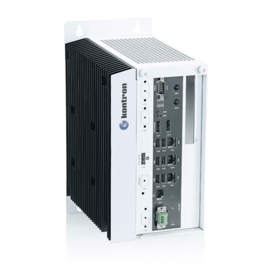
KBox C-103-CFL-x - User Guide, Rev. 1.0 4/ System Overview The KBox C-103-CFL Family is a highly scalable and flexible industrial computer platform that offers high-end performance for industrial automation application such as control or process monitoring. ® The performance scalability is achieved by deploying various Kontron COMExpress CPU modules (form factor basic and type 6 pinout) inside the system. - Page 22 KBox C-103-CFL-x - User Guide, Rev. 1.0 Standard Front Panel: The following interfaces are available with the KBox C-103-CFL: 24VDC input power (X101, optional 2 power input X201) 4x Gigabit Ethernet (X102, X105, X108, X111) 3x USB 3.0 (X103, X106, X109) ...
-
Page 23: Rtc (Goldcap)
KBox C-103-CFL-x - User Guide, Rev. 1.0 4.1. RTC (GoldCap) The baseboard of the KBox C-103-CFL provides an RTC chip connected via the I C Bus. An RTC chip of type RV-8803-C7 or compatible is used. To provide a valid date and time when no power is connected to the system, the carrier is equipped with a goldcap buffer. -
Page 24: Optional Rtc Lithium Battery (Internally-Accessible)
KBox C-103-CFL-x - User Guide, Rev. 1.0 4.2. Optional RTC Lithium Battery (internally-accessible) Your KBox C-103-CFL can be optionally equipped with an internally-accessible lithium battery (CMOS) (see Figure 55). The battery and the battery holder can be accessed after removing the topside access cover (see chapter 6.2. “Opening and Closing the KBox C-103-CFL”). -
Page 25: Internal Usb 3.0 Interface
KBox C-103-CFL-x - User Guide, Rev. 1.0 4.3.5. Internal USB 3.0 Interface The baseboard of KBox C-103-CFL provides one USB3.0 interface (USB A header) and space for a USB A module. This connector can be used to install an internal USB device e.g. a USB Dongle. Please observe the different configuration options, regarding the installation of 2.5"... -
Page 26: Figure 4: Bottom Side View
KBox C-103-CFL-x - User Guide, Rev. 1.0 Figure 4 to Figure 10: Views of a KBox C-103-CFL-2 Figure 4: Bottom side view Figure 6: Front side view Figure 7: Front side view config. with removable config. without Figure 5: Right side view drives removable drives Figure 8: Left side view... -
Page 27: Kbox C-103-Cfl-2 Variant
KBox C-103-CFL-x - User Guide, Rev. 1.0 4.4. KBox C-103-CFL-2 Variant Figure 11: KBox C-103-CFL-2 - front view (shown with removable drive bays and without mounting brackets) X114 RS232/422/ ANT1 ANT2 (optional) Button/LED X112/X113 Button/LED Display Port X104/X107/ X110 USB 2.0 PCIe Slot X103/X106/ X109... -
Page 28: Figure 12: Block Diagram - Kbox C-103-Cfl-X
KBox C-103-CFL-x - User Guide, Rev. 1.0 Figure 12: Block Diagram - KBox C-103-CFL-x www.kontron.com // 28... -
Page 29: Front Side Configuration And Options - Kbox C-103-Cfl
KBox C-103-CFL-x - User Guide, Rev. 1.0 4.5. Front Side Configuration and Options - KBox C-103-CFL Table 3: KBox C-103-CFL Front Side Configuration KBox KBox KBox KBox Standard Interfaces C-103-4 C-103-2 C-103-1 C-103-0 Power Input Connector (X101) Ethernet (X102/X105/X108/X111) USB 3.0 (X103/X106/X109) USB 2.0 (X104/X107/X110) DisplayPort (X112/X113) RS232/422/485 (X114) -
Page 30: X101/X201 - Power Input Connectors
KBox C-103-CFL-x - User Guide, Rev. 1.0 4.5.1. X101/X201 – Power Input Connectors The 3-pin connector (X101) and the optional second power connector (X201) provide the power connection of the KBox C-103-CFL system to an appropriate DC main power supply (see Figure 14 and Figure 11). For pin assignment refer to the subsection 13.1.1. -
Page 31: X112/X113/X203 - Displayports
KBox C-103-CFL-x - User Guide, Rev. 1.0 4.5.5. X112/X113/X203 - DisplayPorts The KBox C-103-CFL provides DisplayPort compliant interfaces realised using two (optional: three) standard DisplayPort connectors. External (digital) displays can be connected to the DisplayPort connectors (X112/X113, optional: X203, Figure 11). For pin assignment refer to subsection 13.1.5. -
Page 32: Rescue Button And Rsq Led
KBox C-103-CFL-x - User Guide, Rev. 1.0 4.5.8. RESCUE Button and RSQ LED The rescue function is not intended for use with a system in an application environment. It is designed to be used if the standard BIOS flash is corrupted, in order to get the system to boot in a defined and safe state for further failure resolution. -
Page 33: Pci/Pcie Expansion Slots
KBox C-103-CFL-x - User Guide, Rev. 1.0 4.5.10. PCI/PCIe Expansion Slots The KBox C-103-CFL provides on the front side up to four slots (see also Figure 11 for KBox C-103-CFL-2) for system expansion with PCI/PCIe expansion cards via corresponding riser cards. To access the corresponding riser card sockets, in order to install or remove PCI/PCIe expansion cards (refer to the subsection 6.3.5 “Riser Cards Expansion Sockets for PCI/PCIe Cards”), you have to remove the top side access cover. -
Page 34: Internal Or Removable 2.5" Sata Hdds/Ssds
KBox C-103-CFL-x - User Guide, Rev. 1.0 4.5.11. Internal or Removable 2.5" SATA HDDs/SSDs Depending on the ordered system configuration, your KBox C-103-CFL-2 can be equipped with up to two drive bays for 2.5" removable SATA HDDs/SSDs (refer to Figure 11, Figure 12) or one internal mounting frame for 2x 2.5"... - Page 35 KBox C-103-CFL-x - User Guide, Rev. 1.0 4.5.11.1. Installing/Removing the removable HDD/SSD To install/remove a removable drive, please perform the following steps: Pull out the lever (Figure 19, pos. 3) of the drive cover (Figure 18, pos. 2) and release it. (If required, unlock the lever with the corresponding key before.) The drive bay cover will spring open and the removable drive will automatically slide out a bit.
-
Page 36: Left And Right Side View
KBox C-103-CFL-x - User Guide, Rev. 1.0 4.6. Left and Right Side View Figure 21: Right side of the KBox C-103-CFL system Figure 22: Left side of the KBox C-103-CFL system ® Top side access cover with knurled screws Screws that secure the COMExpress module 10x screws that secure the right side access cover Screws that secure the cooling fins to the chassis... -
Page 37: Rear Side View
KBox C-103-CFL-x - User Guide, Rev. 1.0 4.8. Rear Side View The KBox C-103-CFL is designed for wall mounting, in vertical position inside of a control cabinet. Please do not remove the red marked screws (see Figure 25, pos. 2 and pos. 4). Please observe the mounting instructions included in the chapter 8/ ”Installation Instructions ”, and the outline dimensions in the subsection 12.1 “Mechanical Specifications of the KBox C-103-CFL”. -
Page 38: 5/ System Extensions
KBox C-103-CFL-x - User Guide, Rev. 1.0 5/ System Extensions Optionally your KBox C-103-CFL can be equipped by factory only, with following ports and additional components: Serial port RS232 or RS422 via an adapter module CAN port: via an adapter module ... -
Page 39: X201 To X206 - Possible Interface Combinations
KBox C-103-CFL-x - User Guide, Rev. 1.0 5.1. X201 to X206 - Possible Interface Combinations The matrix below provides an overview of the possible interface combinations (X201 to X206). Table 5: X201 to X206 Configuration Options 2nd Power Profibus WideLink 3rd DP Profinet/ WiFI... -
Page 40: X205) - Serial Port Rs232/Rs422
KBox C-103-CFL-x - User Guide, Rev. 1.0 5.2. (X205) - Serial Port RS232/RS422 This port can be only factory installed and configured. When you order the KBox C-103-CFL with this extended interface via RS232/422 adapter module, you have to specify in your ordering: ... -
Page 41: X202) - Widelink Port
KBox C-103-CFL-x - User Guide, Rev. 1.0 5.6. (X202) - WideLink Port WideLink is an extension for the KBox C-103-CFL which implements a HDBaseT 2.0 transmitter for video and USB 2.0 signals. The HDBaseT standard can be used to extend the distance between a computer and a monitor of up to 150 meters, depending on the resolution and the cable quality. -
Page 42: Nd 24 Vdc Input
KBox C-103-CFL-x - User Guide, Rev. 1.0 5.8. (X201) 2 24 VDC Input Your KBox C-103-CFL can optionally be extended with a second power input module (X201). Both power connectors have the same pinout. The power source with the highest input voltage will be used to power the system (hot standby). -
Page 43: 8-Channel Gpio/Dio Interface
KBox C-103-CFL-x - User Guide, Rev. 1.0 5.9. 8-Channel GPIO/DIO Interface The KBox C-103-CFL provides an optional 8-channel GPIO/DIO (Digital IO) interface. Figure 29: GPIO connector (cable terminal side of mating connector) This connector contains the 8 GPIO, the power supply for the GPIO and GND. Table 7: GPIO connector pinout Signal Name Direction... -
Page 44: Table 9: Gpio Output Channel
KBox C-103-CFL-x - User Guide, Rev. 1.0 8 GPIOs are implemented. Each GPIO can be select as an output or an input channel. Table 9: GPIO output channel Output Channel Output Type High Side Switch Output Voltage Depends on External Connected Voltage. Allowed Range: 10VDC to 30VDC. -
Page 45: Table 11: Gpio Connector And Mating Connector
KBox C-103-CFL-x - User Guide, Rev. 1.0 Figure 31: Input application connected to GPIO Table 11: GPIO connector and mating connector Manufacturer Mating Cycles Remark Connector Würth Elektronik 691382040012 12-pin, 2.50 mm Horizontal PCB Header with Flanges or equivalentent WR-TBL Serie 382 Max. -
Page 46: Optional Versions With Fan Tray - Kbox C-103-Cfl-4/-2/-1
KBox C-103-CFL-x - User Guide, Rev. 1.0 5.10. Optional Versions with Fan Tray - KBox C-103-CFL-4/-2/-1 By using a fan tray, the KBox C-103-CFL-4/-2/-1 can be operated in a control cabinet with extended ambient temperature; refer to the specified values in the section 12.2 “Environmental Specifications” and chapter 7/ “Thermal Considerations”. -
Page 47: Fan Tray (Only For Kbox C-103-Cfl-4/-2/-1)
KBox C-103-CFL-x - User Guide, Rev. 1.0 5.10.1. Fan Tray (only for KBox C-103-CFL-4/-2/-1) The fan tray can be replaced during operation. This should only be carried-out by qualified personnel, aware of the associated dangers (see subsection 10.3 “Replacing the Fan Tray”). Figure 33: Fan tray components of the KBox C-103-CFL-4/-2/-1 (cable connections between fan and fan connector are included in this assembly) Fan tray with knurled screws... -
Page 48: 6/ Accessing Internal Components
KBox C-103-CFL-x - User Guide, Rev. 1.0 6/ Accessing Internal Components This chapter contains important information that you must read before accessing the internal components. You must follow these procedures properly when installing, removing or handling any system component. It is recommended to expand your system with additional PCI/PCIe/M.2 cards before it is installed into an industrial control cabinet. -
Page 49: Top Cover
KBox C-103-CFL-x - User Guide, Rev. 1.0 6.1. Top Cover The pictures in this section correspond to a KBox C-103-CFL-2 system. The cover description can be applied to all system variants, under consideration of the different mechanical specifications of the KBox C-103-CFL; refer to the section 12.1 “Mechanical Specifications of the KBox C-103-CFL”. -
Page 50: Opening And Closing The Kbox C-103-Cfl
KBox C-103-CFL-x - User Guide, Rev. 1.0 6.2. Opening and Closing the KBox C-103-CFL The pictures in this section correspond to a KBox C-103-CFL-2 system. The “opening/closing” procedure description can be applied to all system variants, under consideration of the different mechanical specifications of the KBox C-103-CFL; refer to the section 12.1 “Mechanical Specifications of the KBox C-103-CFL”. -
Page 51: Figure 37: Kbox C-103-Cfl-2 - Removing The Right Side Cover
KBox C-103-CFL-x - User Guide, Rev. 1.0 Figure 37: KBox C-103-CFL-2 - removing the right side cover For a better accessibility of the internal sockets (PCI/PCIe and M.2 modules), you may also remove the right side cover of the KBox C-103-CFL (Figure 37). Loosen the externally accessible fastening screws (Figure 21, pos. 2) that secure the right side cover (Figure 37 and Figure 21, pos. -
Page 52: Internal View
KBox C-103-CFL-x - User Guide, Rev. 1.0 6.3. Internal View Figure 39: KBox C-103-CFL-2 - internal view (shown with a PCIe riser card and removable HDD/SSD drive bay) Cover retaining bracket on the front side 9 SATA cable connections (power and data) 2 Screws that secure the PCIe slot brackets 10 Baseboard 3 Internal USB 3.0 port with USB cable connected... -
Page 53: Integrated Come Module
KBox C-103-CFL-x - User Guide, Rev. 1.0 6.3.1. Integrated COMe Module Depending on the ordered system configuration, your KBox C-103-CFL accommodates a baseboard with a COMe-bCL6 module. ® Figure 40: KBox C-103-2 - internal view with COMExpress module and with PCIe riser card COM Express module 6 Riser card with 1x PCIe x8 socket 2 Baseboard... -
Page 54: Dip Switch
KBox C-103-CFL-x - User Guide, Rev. 1.0 6.3.3. DIP Switch The baseboard of the KBox C-103.CFL is equipped with an DIP switch (Figure 38, pos. 2). The particular DIP switches have the following functions: DIP switch 1-4: User defined ... -
Page 55: Table 12: Available Riser Cards For The Different Kbox C-103-Cfl Variants
KBox C-103-CFL-x - User Guide, Rev. 1.0 6.3.5.1. Riser Cards for KBox C-103-CFL-x Depending on the variant and system configuration ordered, your KBox C-103-CFL-x can be equipped with different riser cards.The following table shows which riser card is available for which system. Table 12: Available Riser Cards for the different KBox C-103-CFL variants KBox C-103-CFL-4 KBox C-103-CFL-2... -
Page 56: Figure 41: Riser Card With 2Xpcie X4 And 2X Pcie X1 Slots For Kbox C-103-4
KBox C-103-CFL-x - User Guide, Rev. 1.0 6.3.5.2. Detail: Riser Card for KBox C-103-CFL-4 The KBox C-103-CFL-4 is equipped with a riser card that supports 2x PCIe x4 (1x Gen 3, 1x Gen 2) and 2x PCIe x1 (2x Gen2) expansion cards (full-height, half-length form factor). The riser card provides an extra power connector for add-on cards with high power consumption and a “card present”... -
Page 57: Installing/Removing Pci/Pcie Expansion Cards (Kbox C-103-Cfl-4/-2/-1 Only)
KBox C-103-CFL-x - User Guide, Rev. 1.0 6.3.6. Installing/Removing PCI/PCIe Expansion Cards (KBox C-103-CFL-4/-2/-1 only) The PCI/PCIe expansion cards can be installed into the slots on the front side of the system (Figure 11). The slots are marked with “PCIe 1” to “PCIe 4”. It is recommended to expand your KBox C-103-CFL with PCI/PCIe cards before it is installed into a control cabinet. - Page 58 KBox C-103-CFL-x - User Guide, Rev. 1.0 Legend for Figure 42, Figure 43 and Figure 44 : Slot bracket for the for the PCIe 1 expansion slot Free 1x PCI (32 bit) (for PCIe 2 slot) 2 Screws to secure the expansion slot/cards 9 Slot bracket for the for the PCIe 3 expansion slot brackets 10 Slot bracket for the for the PCIe 4 expansion slot...
-
Page 59: Installing/Removing An M.2 Module
KBox C-103-CFL-x - User Guide, Rev. 1.0 6.3.7. Installing/Removing an M.2 Module To install an M.2 module please proceed according to the steps described: Close all applications; shut down the system properly and disconnect the connection to the power source. Disconnect all peripherals. -
Page 60: Installing/Removing A Microsd/Microsim Card
KBox C-103-CFL-x - User Guide, Rev. 1.0 6.3.8. Installing/Removing a microSD/microSIM Card To install a microSD or a microSIM card, please proceed according to the steps described: Close all applications; shut down the system properly and disconnect the connection to the power source. Disconnect all peripherals. -
Page 61: 7/ Thermal Considerations
KBox C-103-CFL-x - User Guide, Rev. 1.0 7/ Thermal Considerations 7.1. Available Processors Please refer to the chapter 12/ “Technical Specifications”. The list of processors is not complete and may be extended over the product lifetime. 7.2. Convection Cooling The KBox C-103-CFL is designed for convection cooling within the specified ambient air temperature ranges. Therefore it is imperative that air flow to and from the unit is guaranteed. -
Page 62: Third Party Components
KBox C-103-CFL-x - User Guide, Rev. 1.0 The maximum system ambient temperature depends mostly on the power consumption of the processor, chipset and third party components: Configurations with HDDs are limited to 50°C maximum ambient temperature. Configurations with wireless components (LTE, WiFi) are limited to 60°C ambient temperature. -
Page 63: 8/ Installation Instructions
KBox C-103-CFL-x - User Guide, Rev. 1.0 8/ Installation Instructions The KBox C-103-CFL comes with attached wall mount brackets. The available mounting key holes (Figure 25, pos. 1 and pos. 3) of the wall mounting brackets allow the unit attaching to a wall of a fire resistant enclosure. Please observe the following safety and installation instructions: ... -
Page 64: Specifications Of The Internal M.2 Connectors
KBox C-103-CFL-x - User Guide, Rev. 1.0 8.1. Specifications of the internal M.2 Connectors Table 14: Specifications of the internal M.2 Connectors M.2 Connector No. M.2 Connector type B-Type M-Type B-Type PCIe lanes/ Gen X1 / G3 X4 /G3 X1 / G3 SATA MicroSIM Mech. -
Page 65: Figure 46: Keep Out Area For Mounting Around Kbox C-103-Cfl-4 (Front Side View Without Fan Tray)
KBox C-103-CFL-x - User Guide, Rev. 1.0 Figure 46: Keep out area for mounting around Figure 47: Keep out area for mounting around KBox C-103-CFL-4 (front side view without fan tray) KBox C-103-CFL-4 (front side view with optional fan tray) www.kontron.com // 65... -
Page 66: Figure 48: Keep Out Area For Mounting Around Kbox C-103-Cfl-2 (Front Side View Without Fan Tray)
KBox C-103-CFL-x - User Guide, Rev. 1.0 Figure 48: Keep out area for mounting around Figure 49: Keep out area for mounting around KBox C-103-CFL-2 (front side view without fan tray) KBox C-103-CFL-2 (front side view with optional fan tray) www.kontron.com // 66... -
Page 67: Figure 50: Keep Out Area For Mounting Around Kbox C-103-Cfl-1 (Front Side View Without Fan Tray)
KBox C-103-CFL-x - User Guide, Rev. 1.0 Figure 50: Keep out area for mounting around Figure 51: Keep out area for mounting around KBox C-103-CFL-1 (front side view without fan tray) KBox C-103-CFL-1 (front side view with optional fan tray) www.kontron.com // 67... -
Page 68: Figure 52: Keep Out Area For Mounting Around Kbox C-103-Cfl-0
KBox C-103-CFL-x - User Guide, Rev. 1.0 Figure 52: Keep out area for mounting around KBox C-103-CFL-0 www.kontron.com // 68... -
Page 69: Dc Power Plug Terminal
KBox C-103-CFL-x - User Guide, Rev. 1.0 8.3. DC Power Plug Terminal The KBox C-103-CFL is connected by a Phoenix connector to a DC power source via a DC power supply wiring (only the Phoenix power plug terminal is included). The KBox C-103-CFL is delivered with a DC power plug terminal (3-pin Phoenix connector). -
Page 70: Side Wall Mounting (Option)
KBox C-103-CFL-x - User Guide, Rev. 1.0 8.4. Side Wall Mounting (Option) Your KBox C-103-CFL can be mounted with optionally available side wall mounting brackets. The key holes of the upper and lower mounting brackets (Figure 54, pos. 3 and pos. 6) allow you to mount the KBox C-103-CFL to a mounting side of the control cabinet in vertical position. -
Page 71: 9/ Starting Up
KBox C-103-CFL-x - User Guide, Rev. 1.0 9/ Starting Up The KBox C-103-CFL must be operated only with the nominal voltage of 24V DC of type SELV. For details refer to the chapter 12/ “Technical Specifications”. 9.1. Connecting to DC Main Power Supply The DC input connector (Figure 11 and Figure 14 marked X101) is located on the front side of the KBox C-103-CFL. -
Page 72: Power Off/On Procedure
KBox C-103-CFL-x - User Guide, Rev. 1.0 Connect the other ends of the DC power wires to the connections of the DC main power supply. Pay attention to the polarity of the connections. Switch on the disconnecting device (circuit breaker) in order to apply voltage to the terminals of the power wires. 9.2. -
Page 73: 10/ Maintenance And Cleaning
KBox C-103-CFL-x - User Guide, Rev. 1.0 10/ Maintenance and Cleaning Equipment from Kontron requires only minimum servicing and maintenance for proper operation. For light soiling, clean the KBox C-103-CFL with a dry cloth. Carefully remove dust from the surface of the cooling fins of the chassis using a clean, soft brush. ... -
Page 74: Preventive Maintenance For Ssd Drives
KBox C-103-CFL-x - User Guide, Rev. 1.0 Danger of explosion when replacing with wrong type of battery. Replace only with the same or equivalent type recommended by the manufacturer. The lithium battery type must be UL recognised. Do not dispose of lithium batteries in general trash collection. Dispose of the battery according to the local regulations dealing with the disposal of these special materials, (e.g. -
Page 75: Cleaning The Air Filter
KBox C-103-CFL-x - User Guide, Rev. 1.0 10.4. Cleaning the Air Filter The air filter is inserted in the holder (Figure 32, pos. 2) at the bottom side of the fan tray slot (Figure 32, pos. 6). The soiling of the air filter (Figure 32, pos. 3) is caused by the pollution of the operating environment. A heavily soiled air filter can cause excessive heating of the device. -
Page 76: Figure 58: Kbox C-103-Cfl-2 With Removed Fan Tray And Removed Air Filter
KBox C-103-CFL-x - User Guide, Rev. 1.0 The pictures in this section correspond to a KBox C-103-CFL-2 system. The description of the procedure for cleaning the air filter can be applied to all KBox C-103-CFL-4/-2/-1 variants, under consideration of the different mechanical specifications. Figure 58: KBox C-103-CFL-2 with removed fan tray and removed Figure 59: Filter mat Holder without air filter air filter... -
Page 77: 11/ Uefi Bios
KBox C-103-CFL-x - User Guide, Rev. 1.0 11/ uEFI BIOS 11.1. Starting the uEFI BIOS The KBox C-103-CFL-x is provided with a Kontron-customized, pre-installed and configured version of AMI Aptio ® V uEFI BIOS based on the Unified Extensible Firmware Interface (uEFI) specification and the Intel® Platform Innovation Framework for EFI. -
Page 78: Setup Menus
KBox C-103-CFL-x - User Guide, Rev. 1.0 11.2. Setup Menus The Setup utility features menus listed in the selection bar at the top of the screen: Main Advanced Chipset Security Boot Save & Exit The left and right arrow keys select the Setup menus. -
Page 79: Main Setup Menu
KBox C-103-CFL-x - User Guide, Rev. 1.0 11.2.1. Main Setup Menu On entering the uEFI BIOS the Setup program displays the Main Setup menu. This screen lists the Main Setup menu sub-screens and provides basic system information as well as functions for setting the system language, time and date. - Page 80 KBox C-103-CFL-x - User Guide, Rev. 1.0 Sub-screen Description Platform Information Read only subscreen Module Information: Displays information about Product Name, Revision Serial #, MAC Adress, Boot Counter and CPLD Revision Carrier Board Information: Displays information about Product Name, Revision, Serial # and Carrier Board ID System Date Displays System Date System Time...
-
Page 81: Advanced Setup Menu
KBox C-103-CFL-x - User Guide, Rev. 1.0 11.2.2. Advanced Setup Menu The Advanced Setup menu provides sub-screens and second level sub-screens with functions, for advanced configuration and Kontron specific configurations. Setting items, on this screen, to incorrect values may cause system malfunctions. Figure 63: Avanced Setup Menu Table 17: Advanced Setup menu Sub-screens and Functions Sub-Screen... - Page 82 KBox C-103-CFL-x - User Guide, Rev. 1.0 Sub-Screen Function Second level Sub-Screen / Description CPU Flex Ratio Override Enable/Disable Intel (VMX) Enable/Disable Virtualization Technology> Active Processor Cores> All/1/2/3 Hyper Threading> Enable/Disable BIST Enable/Disable Power & CPU Power Boot Performance Mode Max Non-Turbo Performance Performance Management Control...
- Page 83 KBox C-103-CFL-x - User Guide, Rev. 1.0 Sub-Screen Function Second level Sub-Screen / Description ICC PLL Shutdown Enable/Disable BCLK Clock Settings Spread %: 47 Trusted Security Device Support Enable/Disable Computing SHA-1 PCR Bank Enable/Disable SHA256 PCR Bank Enable/Disable Pending Operation None Platform Hierarchy Enable/Disable...
- Page 84 KBox C-103-CFL-x - User Guide, Rev. 1.0 Sub-Screen Function Second level Sub-Screen / Description Fan Pulse Fan Trip Point Trip Point Speed Reference Temperature CPU Temperature Serial Port COM0 Console Enable/Disable Console Redirection Redirection Console Redirection Terminal Type VT100/VT100+/VT-UTF8/ANSI Settings Bits per Second 9600/19200/38400/57600/115200 Data Bits...
- Page 85 KBox C-103-CFL-x - User Guide, Rev. 1.0 Sub-Screen Function Second level Sub-Screen / Description Configuration Additional Watchdog Information The COMe-bCL6 provides a two-staged watchdog with: Programmable stages to trigger different actions - If one stage is disabled, then the next stage is also disabled.
- Page 86 KBox C-103-CFL-x - User Guide, Rev. 1.0 Additional SIO Information COM 1 and COM 2 can be treated as 16550-compatible legacy COM interfaces at the standard I/O addresses Additional CSM Information Compatibility Support Module (CSM) configuration is important for legacy operating systems By default, CSM is disabled for modern OS such as Windows 10 and Linux.
-
Page 87: Chipset Setup Menu
KBox C-103-CFL-x - User Guide, Rev. 1.0 11.2.3. Chipset Setup Menu On entering the Chipset Setup menu, the screen lists two sub-screen options: System Agent PCH-IO Entering the System Agent Configuration and PCH-IO Configuration sub-screens provides basic system information and possible functions for these configurations. -
Page 88: Table 18: Chipset: System Agent Configuration Sub-Screens And Functions
KBox C-103-CFL-x - User Guide, Rev. 1.0 11.2.3.1. Chipset: System Agent Configuration Table 18: Chipset: System Agent Configuration Sub-screens and Functions Function Second level Sub-Screen / Description Memory Memory Test on Warm Boot Enable/Disable Configuration Maximum Memory Frequency Auto Max TOLUD Dynamic Fast Boot Enabled/Disabled... -
Page 89: Table 19: Chipset Set > Pch-Io Configuration Sub-Screens And Functions
KBox C-103-CFL-x - User Guide, Rev. 1.0 Function Second level Sub-Screen / Description PEG Width PEG Width 1x8+2x4 rev/2x8 rev Configuration Configuration Stop Grant Auto/Manual Configuration VT-d Enabled/Disabled Above 4GB MMIO Enabled/Disabled BIOS assignment 11.2.3.2. Chipset > PCH-IO Configuration Table 19: Chipset Set > PCH-IO Configuration Sub-screens and Functions Function Second level Sub-Screen / Description PCI Express... - Page 90 KBox C-103-CFL-x - User Guide, Rev. 1.0 Function Second level Sub-Screen / Description SATA and RST SATA Controller Enable/Disable Configuration SATA Mode Selection AHCI SATA Speed Limit Auto/1.5/3/6 Gb/s Software Feature Mask Configuration HDD Unlock Enable/Disable LED Locate Enable/Disable Serial ATA Port 0, 1, 2, 3 Port 0, 1, 2, 3 Enable/Disable External...
-
Page 91: Security Setup Menu
KBox C-103-CFL-x - User Guide, Rev. 1.0 11.2.4. Security Setup Menu The Security Setup menu provides information about the passwords and functions for specifying the security settings. The passwords are case-sensitive. Figure 65: Security Setup Menu Table 20: Security Setup Menu Functions Function Description Administrator Password... - Page 92 KBox C-103-CFL-x - User Guide, Rev. 1.0 11.2.4.1. Remember the Password It is highly recommended to keep a record of all passwords in a safe place. Forgotten passwords results in the user being locked out of the system. If the system cannot be booted because the User Password or the Supervisor Password are not known, see Chapter 11.5 “Updating the uEFI BIOS”...
-
Page 93: Boot Setup Menu
KBox C-103-CFL-x - User Guide, Rev. 1.0 11.2.5. Boot Setup Menu The Boot Setup menu lists dynamically generated boot device priority order. Figure 66: Boot Setup Menu Table 21: Boot Setup Menu Functions Function Description Setup Prompt Timeout Displays number of seconds that the firmware waits before initiating the original default boot selection Bootup NumLock State Selects keyboard NumLock state... -
Page 94: Save And Exit Setup Menu
KBox C-103-CFL-x - User Guide, Rev. 1.0 11.2.6. Save and Exit Setup Menu The Save and Exit Setup menu provides functions for handling changes made to the uEFI BIOS settings and exiting of the Setup program. Figure 67: Save and Exit Setup Menu Table 22: Save and Exit Setup Menu Functions Function Description... -
Page 95: The Uefi Shell
KBox C-103-CFL-x - User Guide, Rev. 1.0 11.3. The uEFI Shell The Kontron uEFI BIOS features a built-in and enhanced version of the uEFI Shell. For a detailed description of the available standard shell scripting, refer to the EFI Shell User Guide. For a detailed description of the available standard shell commands, refer to the EFI Shell Command Manual. -
Page 96: Uefi Shell Scripting
KBox C-103-CFL-x - User Guide, Rev. 1.0 11.4. uEFI Shell Scripting 11.4.1. Startup Scripting If the ESC key is not pressed and the timeout has run out then the uEFI Shell tries to execute some startup scripts automatically. It searches for scripts and executes them in the following order: Initially searches for Kontron flash-stored startup script. -
Page 97: Updating The Uefi Bios
KBox C-103-CFL-x - User Guide, Rev. 1.0 11.5. Updating the uEFI BIOS The KBox C-103-CFL has two SPI boot flashes programmed with the uEFI BIOS, a standard SPI boot flash and a recovery SPI boot flash. The basic idea behind that is to always have at least one working uEFI BIOS flash available regardless if there have been any flashing errors or not. -
Page 98: 12/ Technical Specifications
KBox C-103-CFL-x - User Guide, Rev. 1.0 12/ Technical Specifications Table 23: Technical Specifications KBox C-103-CFL Family Installed COM Express Baseboard with COMe-bCL6 G4930E or Module and Baseboard Baseboard with COMe-bCL6 i3-9100HL or Baseboard with COMe-bCL6 i5-8400H or Baseboard with COMe-bCL6 i7-9850HE or Baseboard with COMe-bCL6 E-2276ME Processor Intel®... - Page 99 KBox C-103-CFL-x - User Guide, Rev. 1.0 KBox C-103-CFL Family Free Expansions Sockets 1x M.2 B-type 1x M.2 B-type 1x M.2 B-type 1x M.2 B-type (internal) 1x full/half size 1x full/half size 1x full/half size 1x full/half size Mini PCIe x1 Mini PCIe x1 Mini PCIe x1 Mini PCIe x1...
-
Page 100: Mechanical Specifications Of The Kbox C-103-Cfl
KBox C-103-CFL-x - User Guide, Rev. 1.0 12.1. Mechanical Specifications of the KBox C-103-CFL 12.1.1. Mechanical Specifications of the KBox C-103-CFL-4 Figure 68: Dimensions: right side (KBox C-103-CFL-4) Figure 69: Dimensions: front side with key holes (KBox C-103-CFL-4) Figure 70: Dimensions: detail key hole (KBox C-103-CFL-4) Figure 71: Dimensions: top side (KBox C-103-CFL-4) www.kontron.com // 100... -
Page 101: Mechanical Specifications Of The Kbox C-103-Cfl-4 With Fan Tray Option
KBox C-103-CFL-x - User Guide, Rev. 1.0 12.1.2. Mechanical Specifications of the KBox C-103-CFL-4 with Fan Tray Option Figure 72: Dimensions: right side Figure 73: Dimensions: front side with key holes (KBox C-103-CFL-4 with fan tray option) (KBox C-103-CFL-4 with fan tray option) Figure 74: Dimensions: detail key hole Figure 75: Dimensions: top side (KBox C-103-CFL-4 with fan tray option) -
Page 102: Table 24: Mechanical Specifications Of The Kbox C-103-Cfl-4
KBox C-103-CFL-x - User Guide, Rev. 1.0 Table 24: Mechanical Specifications of the KBox C-103-CFL-4 Dimensions KBox C-103-CFL-4 (Standard Version) KBox C-103-CFL-4 (with optional Fan Tray) Height with mounting brackets: 290 mm (11.42") with mounting brackets: 324 mm (12.756") Width 195 mm (6.10") 195 mm (6.10") Depth... -
Page 103: Mechanical Specifications Of The Kbox C-103-Cfl-2
KBox C-103-CFL-x - User Guide, Rev. 1.0 12.1.3. Mechanical Specifications of the KBox C-103-CFL-2 Figure 76: Dimensions: right side (KBox C-103-CFL-2) Figure 77: Dimensions: front side with key holes (KBox C-103-CFL-2) Figure 78: Dimensions: detail key hole (KBox C-103-CFL-2) Figure 79: Dimensions: top side (KBox C-103-CFL-2) www.kontron.com // 103... -
Page 104: Mechanical Specifications Of The Kbox C-103-Cfl-2 With Fan Tray Option
KBox C-103-CFL-x - User Guide, Rev. 1.0 12.1.4. Mechanical Specifications of the KBox C-103-CFL-2 with Fan Tray Option Figure 80: Dimensions: right side Figure 81: Dimensions: front side with key holes (KBox C-103-CFL-2 with fan tray option) (KBox C-103-CFL-2 with fan tray option) Figure 82: Dimensions: detail key hole Figure 83: Dimensions: top side (KBox C-103-CFL-2 with fan tray option) -
Page 105: Table 25: Mechanical Specifications Of The Kbox C-103-Cfl-2
KBox C-103-CFL-x - User Guide, Rev. 1.0 Table 25: Mechanical Specifications of the KBox C-103-CFL-2 Dimensions KBox C-103-CFL-2 (Standard Version) KBox C-103-CFL-2 (with optional Fan Tray) Height with mounting brackets: 290 mm (11.42") with mounting brackets: 324 mm (12.756") Width 155 mm (6.10") 155 mm (6.10") Depth... -
Page 106: Mechanical Specifications Of The Kbox C-103-Cfl-1
KBox C-103-CFL-x - User Guide, Rev. 1.0 12.1.5. Mechanical Specifications of the KBox C-103-CFL-1 Figure 84: Dimensions: right side (KBox C-103-CFL-1) Figure 85: Dimensions: front side with key holes (KBox C-103-CFL-1) Figure 86: Dimensions: detail key hole (KBox C-103-CFL-1) Figure 87: Dimensions: top side (KBox C-103-CFL-1) www.kontron.com // 106... -
Page 107: Mechanical Specifications Of The Kbox C-103-Cfl-1 With Fan Tray Option
KBox C-103-CFL-x - User Guide, Rev. 1.0 12.1.6. Mechanical Specifications of the KBox C-103-CFL-1 with Fan Tray Option Figure 88: Dimensions: right side Figure 89: Dimensions: front side with key holes (KBox C-103-CFL-1 with fan tray option) (KBox C-103-CFL-1 with fan tray option) Figure 90: Dimensions: detail key hole Figure 91: Dimensions: top side (KBox C-103-CFL-1 with fan tray option) -
Page 108: Table 26: Mechanical Specifications Of The Kbox C-103-Cfl-1
KBox C-103-CFL-x - User Guide, Rev. 1.0 Table 26: Mechanical Specifications of the KBox C-103-CFL-1 Dimensions KBox C-103-CFL-1 (Standard Version) KBox C-103-CFL-1 (with optional Fan Tray) Height with mounting brackets: 290 mm (11.42") with mounting brackets: 324 mm (12.756") Width 130 mm (5.12") 130 mm (5.12") Depth... -
Page 109: Mechanical Specifications Of The Kbox C-103-0
KBox C-103-CFL-x - User Guide, Rev. 1.0 12.1.7. Mechanical Specifications of the KBox C-103-0 Figure 92: Dimensions: right side (KBox C-103-0) Figure 93: Dimensions: front side with key holes (KBox C-103-0) Figure 94: Dimensions: detail key hole (KBox C-103-0) Figure 95: Dimensions: top side (KBox C-103-0) www.kontron.com // 109... -
Page 110: Table 27: Mechanical Specifications Of The Kbox C-103-1
KBox C-103-CFL-x - User Guide, Rev. 1.0 Table 27: Mechanical Specifications of the KBox C-103-1 Dimensions KBox C-103-0 (Standard Version) Height with mounting brackets: 290 mm (11.42") Width 117 mm (4.61") Depth with mounting brackets: 210 mm (8.26 ") Weight Approx. -
Page 111: Environmental Specifications
KBox C-103-CFL-x - User Guide, Rev. 1.0 12.2. Environmental Specifications Table 28: Environmental Specifications KBox C-103-CFL Thermal Management Convection cooling/with fan Operating Temperature Intel® Celeron™ G4930E: 0°C to +70°C (32°F to 158°F) Intel® Core™ i3-9100HL: 0°C to +70°C (32°F to 158°F) Intel®... -
Page 112: Standards, Certifications And Directives Compliance
KBox C-103-CFL-x - User Guide, Rev. 1.0 12.3. Standards, Certifications and Directives Compliance Table 29: Standards, Certifications and Directives Compliance CE-Mark Electromagnetic Compatibility Directive 2014/30/EU Compliant Low Voltage Directive 2014/35/EU with EU Radio Equipment Directive (RED) Directive 2014/53/EU Directives RoHS II Directive 2011/65/EU CISPR 11 Industrial, scientific and medical equipment - Radio-... -
Page 113: Table 30: Electrical Safety
KBox C-103-CFL-x - User Guide, Rev. 1.0 Safety IEC 61010-1 Safety requirements for electrical equipment for measurement, control and laboratory use - Part 1: General 2014/35/EU EN 61010-1 requirements UL 61010-1 IEC 61010-2-201 Safety requirements for electrical equipment for measurement, control and laboratory use - Part 2-201: EN 61010-2-201 Particular requirements for control equipment UL 61010-2-201... -
Page 114: Power Supply Specification
KBox C-103-CFL-x - User Guide, Rev. 1.0 12.4. Power Supply Specification Before connecting the product to a mains power supply, ensure that the power supply meets the required electrical specification for the product and that protection and supply limitation have been taken into consideration. The power supply used must also automatically recover from AC power loss and start up under peak loading. -
Page 115: Power Consumption
KBox C-103-CFL-x - User Guide, Rev. 1.0 12.4.2. Power Consumption The used external power supply must be capable of delivering the product with the required power when configured with all components. The total power consumption depends on factors such as the CPU, interfaces, and system/memory expansion. -
Page 116: 13/ Standard Interfaces - Pin Assignments
KBox C-103-CFL-x - User Guide, Rev. 1.0 13/ Standard Interfaces – Pin Assignments Low-active signals are indicated by a minus sign. 13.1.1. (X101) Power Input Connector Table 33: (X101) Power Input Connector Signal Name 3-pin POWER SUBCON (male) +24 VDC (input) Ground 0V (input) 13.1.2. -
Page 117: X103, X106, X109) Usb 3.0 Ports
KBox C-103-CFL-x - User Guide, Rev. 1.0 13.1.3. (X103, X106, X109) USB 3.0 Ports Table 35: (X103, X106, X109) USB 3.0 Ports Signal Name Signal Name 9-pin USB Connector Type A Version 3.0/2.0 USB 2.0 contact pins USB 3.0 contact pins VCC, fused (900 mA max.) StdA_SSRX- Data-... -
Page 118: X114) Serial Interface Com 1 (Rs232, Rs422, Rs485)
KBox C-103-CFL-x - User Guide, Rev. 1.0 13.1.6. (X114) Serial Interface COM 1 (RS232, RS422, RS485) The mode can be selected in the BIOS Table 38: (X114) Serial Interface COM 1, configured as RS232) Signal Name 9-pin D-SUB Connector (male) (Data Carrier Detect) (Receive Data) (Transmit Data) -
Page 119: Table 41: (X114) Serial Interface Com 1 And Com2, Configured As Dual Rs485
KBox C-103-CFL-x - User Guide, Rev. 1.0 Table 41: (X114) Serial Interface COM 1 and COM2, configured as dual RS485 Signal Name 9-pin D-SUB Connector (male) TxD/RxD- (COM1 Data -) TxD/RxD+ (COM1 Data+) (Signal Ground) TxD/RxD- (COM2 Data -) TxD/RxD+ (COM2 Data+) Table42: (X114) Serial Interface COM 1 and COM2, configured as dual RS422 Signal Name 9-pin D-SUB Connector (male) -
Page 120: Optional Interfaces Via Adapter Modules
KBox C-103-CFL-x - User Guide, Rev. 1.0 13.2. Optional Interfaces via Adapter Modules 13.2.1. (X201) 2 Power Input Connector For pin assignment, refer to 13.1.1. 13.2.2. (X 202) WideLink This port must be factory installed and configured only. Your KBox C-103 can either be equipped with a 3 DisplayPort or a WideLink port. -
Page 121: 205) Serial Port Rs232/Rs422
KBox C-103-CFL-x - User Guide, Rev. 1.0 13.2.4. (X 205) Serial Port RS232/RS422 This port must be factory installed and configured only. When you order the KBox C-103 with this extended interface via RS232/422 adapter module, you have to specify in your ordering: ... -
Page 122: 204) Can Bus Port
KBox C-103-CFL-x - User Guide, Rev. 1.0 13.2.5. (X 204) CAN Bus Port If a termination resistor (120Ω) is required, you have to make a connection (bridge) between pin 1 and 2, respectively pin 7 and 8, in order to enable the onboard termination resistor (120Ω). -
Page 123: Appendix A: List Of Acronyms
KBox C-103-CFL-x - User Guide, Rev. 1.0 Appendix A: List of Acronyms Table 47: List of Acronyms (Example) Application Programming Interface Base Management Controller Command-Line Interface Computer-on-Module Error Checking and Correction Field Replaceable Unit Graphics Processing Unit HD/HDD Hard Disk /Drive PICMG Hardware Platform Management specification family IPMI-Over-LAN... - Page 124 KBox C-103-CFL-x - User Guide, Rev. 1.0 www.kontron.com // 124...
-
Page 125: About Kontron
KBox C-103-CFL-x – User Guide, Rev. 1.0 About Kontron Kontron is a global leader in IoT/Embedded Computing Technology (ECT). As a part of technology group S&T, Kontron, together with its sister company S&T Technologies, offers a combined portfolio of secure hardware, middleware and services for Internet of Things (IoT) and Industry 4.0 applications.
Need help?
Do you have a question about the kontron KBox C-103-CFL Series and is the answer not in the manual?
Questions and answers