Table of Contents
Advertisement
Quick Links
Operation and Maintenance Guide
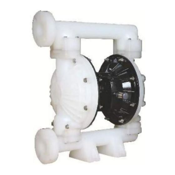
SDP50PPTB, 2" Diaphragm pump
Read this manual carefully before installing, operating or servicing this equipment. It's the responsibility of the employer to ensure this
manual is read by the operator. Please preserve this manual.
Product Sr No.
&
are trademarks of Teryair Equipment Pvt. Ltd.
Advertisement
Table of Contents

Related Manuals for Teryair SDP50PPTB


Summary of Contents for Teryair SDP50PPTB
- Page 1 Read this manual carefully before installing, operating or servicing this equipment. It’s the responsibility of the employer to ensure this manual is read by the operator. Please preserve this manual. Product Sr No. & are trademarks of Teryair Equipment Pvt. Ltd.
-
Page 2: Pump Nomenclature
Suction Model No Ball Material @ 90 PSI and Max. Weight Material Material Material Material Capacity Flow Bonded SDP50PPTB 6.0 mtrs 108 C.F.M. 28 Kg (Buna+PTFE) Pump Data B Pump Data C Description Value Non wetted part Polypropylene Center Section... -
Page 3: Operating And Safety Precautions
Please check compatibility of fluids intended to be and fitting as instructed handled with the materials of construction of the Use genuine Teryair parts to ensure correct pump pump. Severe reactions and explosions may occur operation and maximize life. if materials are incompatible. - Page 4 Caution:Temperature limitations Elastomer Minimum allowable Maximum allowable temperature temperature PTFE +40° F +225° F +4°C +107°C Santoprene® -40° F +225° F -40°C +107°C Hytrel® -20° F +150° F -29°C +66°C Suggested Lubricants 5 deg C to 27 Below 5 deg Above 27 deg C deg C (40 degF to (80 deg F)
- Page 5 Intended use and Prohibitive use These conditions are adequately described in operating and safety precautions. The list of chemical and fluids are too huge to list here. Standard industry practice is to refer a accepted chemical compatibility guide such as Cole Parmeretc to establish compatibility. See section caution: Chemical compatibility earlier in this document.
-
Page 6: Troubleshooting
Operating Instructions The Teryair Stroke diaphragm pump generates a alternate stroking of the diaphragms against the fluid in the liquid chambers of the Pump. This reciprocatory action is responsible for the fluid being pumped. It is possible to control the output of the pump by controlling the supply air pressure. -
Page 7: Maintenance
Follow the instructions clearly for disassembly and assembly of the pump and in the troubleshooting section. Use genuine teryair spares and if possible mention the serial number of the pump when ordering spares. Always replace elastomers as a set, eg diaphragms, balls and seats Dis-assembly and Re assembly Shut off air supply and allow residual Pressure to bleed off. - Page 8 2) Replacement of Shaft O rings For removing the rubber rings (9) from center piece assembly, first follow the steps a, b, c, d, e & f from the diaphragm replacement. This time need to remove both the diaphragm from any one side and on the other side you can remove the diaphragm with the shaft.
- Page 9 4) Replacement of secondary shaft assembly a) For removing the secondary shaft assembly from center piece assembly, first follow the steps a, b, c, d from the diaphragm replacement and remove the outer chamber (6). b) Repeat the same procedure to remove the other side also. c) Remove the oring (39) from both sides of secondary shaft assembly (41).
-
Page 10: Exploded Views
Exploded views SDP50PPTB MM-345-REV - 02... - Page 11 Bill of Material SDP50PPTB ITEM PART ITEM PART DESCRIPTION QTY. DESCRIPTION QTY. NUMBER NUMBER 203 10 01 Centre Piece With Insert 203 90 04S Hex Bolt M8x45L -SS 203 10 02 Air Disc 203 90 05S Hex Bolt M8x70L -SS...
Need help?
Do you have a question about the SDP50PPTB and is the answer not in the manual?
Questions and answers