Table of Contents
Advertisement
Quick Links
Advertisement
Table of Contents

Subscribe to Our Youtube Channel
Related Manuals for Bosch C900TTL-E


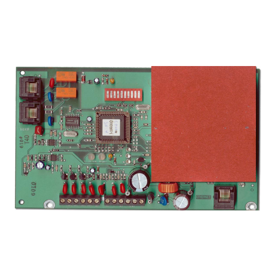
Summary of Contents for Bosch C900TTL-E
- Page 1 C900TTL-E Installation Guide Dialer Capture Module...
-
Page 2: Trademarks
EN | 2 1. C900TTL-E | Installation Guide | Trademarks Trademarks ® ® ® Microsoft , MS-DOS , Windows 98, ME, 2000, XP, ® and Windows NT are either registered trademarks or trademarks of Microsoft Corporation in the United States and/or other countries. -
Page 3: Table Of Contents
2.3.1 Inputs ..............9 2.3.2 Outputs ..............9 Figures Power Terminal Strip ........10 Figure 1: C900TTL-E Location of Major Features ..5 Phone Connections ..........10 Figure 2: Mounting the C900TTL-E on the Ethernet Connections........10 Optional Plate Mount ........6 C900TTL-E Setup ...........11 Figure 3: Attaching the Enclosure Door ...... - Page 4 EN | 4 1. C900TTL-E | Installation Guide | UL Listings and Approvals Tables Table 1: Power Terminal Strip Functions ....10 Table 2: Digital Dialer Protocol for DIP Switches 1-4, and 10 ........11 Table 3: C900TTL-E Programming for Switches 5-9 ...........12 Table 4: Dialer LED Functions ........13...
-
Page 5: 1.0 Introduction
(data output) to an Ethernet connection on a local area network (LAN) or wide area network (WAN). When the dialer has data to report, the C900TTL-E provides the signals and voltages necessary to simulate a public switched telephone network (PSTN) connection to the central station. -
Page 6: Mounting
Mounting holes in the mounting plate brackets. The C900TTL-E is static sensitive. Ensure 3. Place the top edge of the C900TTL-E module that you touch earth ground before (6) under the standoff bracket of the upper two handling the circuit board to discharge any standoffs (2). -
Page 7: Attaching The Module To The Enclosure Door
(4). module is installed. 2. Position the mounting plate closest to the edge 1. Place the top edge of the C900TTL-E module (1) opposite the door hinge. between the two slots (8) on the inside top of the enclosure (7). -
Page 8: Wiring
Installation Wiring The C900TTL-E can be used with a variety of control panels (refer to Figure 16 on page 25). This section provides instructions for wiring the C900TTL-E to a DS7400Xi. The C900TTL-E intercepts the phone line between the telco service and the control panel, making the control panel’s phone line monitor inactive. -
Page 9: Input/Output Functions
Zone alarm report allows the digital dialer (if used) when the dialer begins to dial. Input 3 cannot force to indicate a failure of the C900TTL-E to the an intercept if the C900TTL-E is in Fallback central station, or to locally annunciate a failure if because of an error, command, or input 2 high. -
Page 10: Power Terminal Strip
(if used) to indicate to the central station a failure of the C900TTL-E, or to act as a means to annunciate a failure locally if the network communications path fails. -
Page 11: 3.0 C900Ttl-E Setup
Reserved Reserved Reserved Telim** Robofon** Reserved Reserved Reserved Reserved DTMF includes Contact ID, High Speed and 4/2 Express. ** C900TTL-E version 1.11 or later. These formats are not approved for UL 1610. Bosch Security Systems, Inc. | 5/07 | 4998122718-02... -
Page 12: Table 2: Digital Dialer Protocol For Dip Switches 1-4, And 10
If an error occurs in the Intercept Mode, the C900TTL-E automatically switches back to telco line. If the D6600 does not acknowledge a report that was intercepted by the C900TTL-E within the programmed time, the digital dialer hangs up and retries the message transmission. The programmed time is measured as a failed message transmission at the digital dialer. Based on the number of hang-ups, the C900TTL-E switches to Fallback Mode. -
Page 13: Leds
If Auto Fallback After Error is enabled (Switch 5 = ON), the C900TTL-E connects the dialer to the phone line on the next line seizure. If the dialer does not seize the line, this condition ends after two minutes. -
Page 14: System Led
If the dialer sends a valid message, the LED returns to a blinking green status. If the dialer hangs up, an intercept error is generated. The alternating LED also occurs when the line is seized, but no transaction is occurring (for example, the C900TTL-E is waiting for the dialer to return on-hook). -
Page 15: Fallback Mode
Fallback Mode In fallback operation, the C900TTL-E connects the PSTN to the dialer and the dialer to the telco, shunting itself out of the phone circuit. Intercept mode is maintained only if the C900TTL-E processor is running, and no errors occur. -
Page 16: Ip Address Configuration Setup Instructions
Finish the Configuration on page 18. duplicates. Before you can program the IP address of the C900TTL-E, find the media access control (MAC) or hardware address of the C900TTL-E. The MAC address is hard-coded into the C900TTL-E during its manufacture and cannot be changed. -
Page 17: Using Arp.exe To Assign An Initial Ip Address
ARP command to assign the new IP accepted. address for the C900TTL-E. ARP is a program used to associate the C900TTL-E IP address with its MAC address temporarily. The ARP program is placed in the C:/WINDOWS directory by ®... -
Page 18: Using Telnet To Finish The Configuration
The Telnet application should now be running. 7. Select Connect→Remote System… 3. Select Connect Remote System... 8. This time, type 9999 into the Port field and accept the other fields. Click Connect. The Connect window appears: Bosch Security Systems, Inc. | 5/07 | 4998122718-02... - Page 19 C900TTL-E | Installation Guide | 4.0 IP Address Configuration Setup Instructions For example, if this C900TTL-E was originally The message, Press Enter to go into programmed to IP address 190.200.128.152, we setup mode, appears. could change the address to 190.200.128.219.
-
Page 20: Figure 14:Setting Values In A Telnet Session
255.255.192.0 255.255.128.0 255.255.0.0 Be careful not to enter a password into the 255.254.0.0 C900TTL-E by accident or to select [Y] to 255.252.0.0 change the password. If you enter a 255.248.0.0 password, store it in a secured place. If the 255.240.0.0 password is lost or forgotten, you cannot communicate with this unit again. -
Page 21: Figure 15:C900Ttl-E Encryption
6- Security and follow the steps in Figure 15. 00 is not the default value, type [00] and press [ENTER] to change it. If encryption is enabled on the C900TTL-E, it must be enabled at the D6680 with the same key. -
Page 22: Using Windows 2000 Or Windows Xp
C900TTL-E is communicating with the network. 6. The connection fails the first time. This is normal. Configuration of the C900TTL-E is complete. Perform At the prompt, enter the same sequence but use this procedure for any additional C900TTL-E modules. -
Page 23: Enabling Dynamic Host Configuration Protocol (Dhcp)
D6200 Programming Software. Refer to the D6200 Programming Software Operation and Installation Guide (P/N: 4998154991). • Network connections are configured to communicate through a DHCP server. • The IP address of the C900TTL-E is set to 0.0.0.0. Bosch Security Systems, Inc. | 5/07 | 4998122718-02... -
Page 24: Ul Standard 1610 Intrusion System Installations
C900TTL-E | Installation Guide | 6.0 UL Standard 1610 Intrusion System Installations 6. Connect Output 2 from the C900TTL-E to a 6.0 UL Standard 1610 Intrusion second D130 Relay Module connected to a 24-hour zone on the control panel. This provides a System Installations method to locally annunciate a network failure. -
Page 25: Figure 16:C900Ttl-E And Generic Control Panel In Separate Enclosures Componentlocations (Ul Standard 1610, No Telephone Line) (Ul Standard 864)
C900TTL-E | Installation Guide | 6.0 UL Standard 1610 Intrusion System Installations Figure 16: C900TTL-E and Generic Control Panel in Separate Enclosures Component Locations (UL Standard 1610, No Telephone Line) (UL Standard 864) PA N EL 1 2 3 45 6 7 8 910... -
Page 26: Figure 17:Control Panel Connection Sequence
24-hour zone input COM (D130 No.1) 24-hour zone input common Common tamper switches Enclosure tamper switch Enclosure tamper switch Battery negative Battery negative terminal Battery positive Battery positive terminal AC transformer AC transformer Bosch Security Systems, Inc. | 5/07 | 4998122718-02... -
Page 27: Setting The Dip Switch
Ensure that DIP Switches 10, 1, 2, 3, and 4 are set for the correct format. If the control panel’s format does not match the C900TTL-E’s format, the C900TTL-E sends a Dialer Error or No Response to Handshake message to the receiver. -
Page 28: Protected Premises Control Panel With Digital Dialer Backup
1 If an error occurs in the Intercept Mode, the C900TTL-E automatically falls back to the telco line. 2 If the D6600 does not acknowledge a report that was intercepted by the C900TTL-E in the proper amount of time, the digital dialer hangs up and retries the message transmission. -
Page 29: C900Ttl-E And Generic Control Panel In Separate Enclosures
C900TTL-E | Installation Guide | 6.0 UL Standard 1610 Intrusion System Installations 7. Use the C900TTL-E with a UL Listed Burglary 6.2.2 Setting the DIP Switch Alarm Control Unit or a UL Listed combination A 10-position DIP switch programs the C900TTL-E. -
Page 30: Ul Standard 864 For Fire System Installations
C900TTL-E. NFPA-72. 5. Connect Output No 1 from the C900TTL-E to a If the control panels are used for fire D130 Relay Module connected to the same applications, test according to NFPA-72. -
Page 31: Setting The Dip Switch
Intercept errors are always reported to Switch positions 1 through 4, and 10 work together the D6600. If the D6600 does not to program the dialer format into the C900TTL-E. acknowledge a signal that was intercepted by the C900TTL-E in the... - Page 32 Bosch Security Systems, Inc. 130 Perinton Parkway Fairport, NY 14450-9199 Customer Service: (800) 289-0096 Technical Support: (888) 886-6189 © 2007 Bosch Security Systems, Inc. 4998122718-02...
Need help?
Do you have a question about the C900TTL-E and is the answer not in the manual?
Questions and answers