Table of Contents
Advertisement
Quick Links
Advertisement
Table of Contents

Related Manuals for Bosch CFB 840


Summary of Contents for Bosch CFB 840
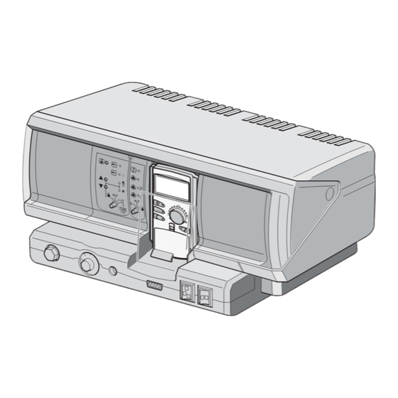
- Page 1 Control Unit CFB 840 Servicing instructions for heating contractors...
-
Page 2: Table Of Contents
9.1.1 Low temperature boilers ......20 2.7.1 Controller CFB 840 ......5 9.1.2 Ecostream boilers . - Page 3 Keyword index ........51 CFB 840...
-
Page 4: Key To Symbols And Safety Instructions
Determined use environment. The CFB 840 control unit is designed to control heating systems in B Ensure that only a qualified contractor carries out installation, detached houses, apartment buildings, residential complexes and other connection of exhaust system, commissioning, maintenance and buildings. -
Page 5: Notes On Commissioning
The digital CFB 840 control unit is suitable for regulating a floor-standing Sensor in °C in °C in °C in °C oil/gas-fired boiler with single stage, two-stage or modulating burner. FV1 flow temp. HC <... -
Page 6: Adjusting The High Limit Safety Cut-Out
B Re-tighten screw [3]. (observe the relevant notice), the boiler temperature controller setting can be changed from 90 °C to 105 °C. B Pull off rotary dial. B Break off the end stop tabs [1]. 6 720 802 836 (2012/05) CFB 840... -
Page 7: Controls And Programming Unit
Slot 1, e.g. FM442/CMM 920 - heating circuit 1, heating circuit 2 Slot B: Programmer (CM431) - programming unit Slot A: ZM422 - feed for external heat sources, heating circuit 0 Slot 2, e.g. FM442/CMM 920 - heating circuit 3, heating circuit 4 CFB 840 6 720 802 836 (2012/05) -
Page 8: Programmer Programming Unit
[14] Automatic heating mode in accordance with a time switch Summer/wintertime changeover [15] Constant heating mode Back to the standard display [16] Rotary dial Select a time switch program [17] Display Selecting heating circuits/DHW circuit 6 720 802 836 (2012/05) CFB 840... -
Page 9: Modules And Their Function
Address Description Modules and their function Stand-alone control unit: All modules which are or can be fitted into your CFB 840 control unit are Set the address to 0 if the control unit operates as stand- shown here. alone equipment (factory setting). -
Page 10: Nm482 Power Supply Module
10 | Modules and their function NM482 power supply module Central module ZM422 The ZM422 module is part of the basic equipment of the CFB 840 End connection when networking several control units control unit. The manual switches on the module are only provided for service and maintenance functions. -
Page 11: Burner Function
Current functions are indicated by LEDs. Heating circuit in summer mode Heating circuit pump operational "Mixing valve opens" (hotter) "Mixing valve closes" (colder) Manual heating circuit switch e.g. for heating circuit 1 and 2 CFB 840 6 720 802 836 (2012/05) -
Page 12: Commissioning
If a brand new Programmer has been installed in the control unit and the connections with the control unit have been established, data are immediately downloaded from the control unit. The display shows Monitor data will from ctrl unit taken. 6 720 802 836 (2012/05) CFB 840... -
Page 13: Checking The High Limit Safety Cut-Out (Stb)
STB to be broken. In this case the broken high limit safety cut-out must be replaced. 6 720 803 704-10.1T Fig. 13 Checking the STB using the burner emergency operation switch Thermostat selector button Burner emergency operation switch CFB 840 6 720 802 836 (2012/05) -
Page 14: Resetting The High Limit Safety Cut-Out
Fig. 14 Triggering the high limit safety cut-out Lever 6.2.3 Resetting the high limit safety cut-out Fig. 15 Resetting the high limit safety cut-out B Undo the cap. B Push the reset button underneath. B Refit the cap. 6 720 802 836 (2012/05) CFB 840... -
Page 15: Settings
Version Boiler raising Control unit Reset Control unit settings Burner Hours run Fault log Maximum flue gas temperature Heat yield Maint. message 6 720 802 836-08.1TL Fig. 16 Adjustable parameters and display data CFB 840 6 720 802 836 (2012/05) -
Page 16: Calling Up The Service Level
7.2.2 Calling up main menus The rotary dial is used to scroll through the main menu. The main menus are structured as a loop and recommence after the last main menu. 6 720 802 836 (2012/05) CFB 840... -
Page 17: Minimum Outside Temperature
B Hold down button Display and turn the rotary dial until the required value is shown. The display shows the set value. B Release Display to save your input. B Press Back to return to the next higher level. CFB 840 6 720 802 836 (2012/05) -
Page 18: Type Of Building
Well screened boiler rooms in cellars can restrict the reception of the radio clock signal, which makes it necessary for you to set the date and time manually. Do not enable the "Radio clock" function outside Germany. 6 720 802 836 (2012/05) CFB 840... -
Page 19: Remote Adjust
The remote adjustment offers the option of external data entry and closed. adjustment via a remote system. If Fault message is shown, an entry also appears in the fault log. Automatic forwarding via the CFB 840 Setting telecontrol system is then possible. options Explanation If cent. -
Page 20: Module Selection
B Press Back to return to the next higher level. The maintenance message is recorded in the fault log Select boiler type and can be transferred via the CFB 840 telecontrol Subject to the selected boiler type, special setting options will be system. -
Page 21: Ecostream Boilers
Ecostream is to be regulated by an external regulates the boiler operating temperature in the boiler flow. These set control unit, e.g. if the CFB 840 does not need to fulfil any operating values always apply, if a load demand exists for the boiler via a conditions, for example in dual-block boiler systems with integral consumer, irrespective of whether the burner is switched on or off. -
Page 22: Setting The Burner Type
This setting must be used in the following cases: B Press Back to return to the next higher level. – For a boiler sequence comprising two single stage boilers that are operated with only one CFB 840 on the 1st boiler and a constant Input range Factory setting control unit on the 2nd boiler. -
Page 23: General Settings Regarding Boiler Parameters
B Hold down button Display and turn the rotary dial until the required Table 34 Setting range Minimum start temperature value is shown. B Release Display to save your input. B Press Back to return to the next higher level. CFB 840 6 720 802 836 (2012/05) -
Page 24: Selecting The Maximum Shutdown Temperature
HEAT CIRC. DATA Heating system Underfloor 6 720 802 836-40.1TL Fig. 26 Select the heating system B Release Display to save your input. B Press Back to return to the next higher level. 6 720 802 836 (2012/05) CFB 840... -
Page 25: Rename The Heating Circuit
B Turn the rotary dial until submenu Heating system appears. B Hold down button Display and turn the rotary dial until the required value is shown. B Release Display to save your input. CFB 840 6 720 802 836 (2012/05) -
Page 26: Setting The Minimum Flow Temperature
• Night setback with hold room temperature • Max. room influence If the heating system Constant is selected, this parameter cannot be adjusted. • Automatic adaptation • Optimisation • Heating system Room controller 6 720 802 836 (2012/05) CFB 840... -
Page 27: Maximum Room Influence Setting
The maximum room [ambient] influence limits the influence of the room temperature (room temperature hook-up) on the set flow temperature. The value determines the maximum room temperature setback for rooms which are not equipped with remote controls. CFB 840 6 720 802 836 (2012/05) -
Page 28: Setting The Outside Stop Temperature
B Hold down button Display and turn the rotary dial until the required value is shown. 6 720 802 836-49.1TL Fig. 35 Setting the outside stop temperature B Release Display to save your input. B Press Back to return to the next higher level. 6 720 802 836 (2012/05) CFB 840... -
Page 29: Setting Flow Setback
Table 51 Setting range Flow setback and flow temperatures. Conditions are: • A representative room with reference temperature. • Fully opened thermostatic valves in the room. • No constantly fluctuating external heat influence. CFB 840 6 720 802 836 (2012/05) -
Page 30: Setting Switching Optimisation
Input range Factory setting optimisation is not suitable for systems with a long heat- Stop optim. time 10 min – 60 min 60 min up time. Table 57 Setting range Stop optimisation time 6 720 802 836 (2012/05) CFB 840... -
Page 31: Setting Frost Protection Temperature
Table 60 Setting range Actuator HEAT CIRC. DATA DHW priority 6 720 802 836-58.1TL Fig. 44 Setting DHW priority B Release Display to save your input. B Press Back to return to the next higher level. CFB 840 6 720 802 836 (2012/05) -
Page 32: Set The Actuator Run-Time
Menu item External changeover is only displayed if 90sec under menu option Remote control – none has been selected and control unit CFB 840 is installed. The menu item is also not shown if heating system Room 6 720 802 836-60.1TL thermostat is selected since this requires a remote Fig. -
Page 33: External Fault Message Pump
B Hold down button Display and turn the rotary dial until the required value is shown. HEAT CIRC. DATA External fault message pump via WF1/2 6 720 802 836-63.1TL Fig. 49 External fault message - pump CFB 840 6 720 802 836 (2012/05) -
Page 34: Setting The Temperature Rise
10.25.2 Setting the heat-up time Setting the parameter Increase in which daily cycle the temperature should rise to dry out the screed. B Turn the rotary dial until submenu Screed drying Temp increase appears. 6 720 802 836 (2012/05) CFB 840... -
Page 35: Setting The Hold Time
B Do not draw off DHW unmixed. B Call up the service level. GENERAL PARAM. appears as the first main menu. B Turn the rotary dial until main menu DHW appears. B Press Display to call up a submenu. CFB 840 6 720 802 836 (2012/05) -
Page 36: Selecting Switching Optimisation
B Hold down button Display and turn the rotary dial until the required If the function Residual heat utilisation is selected, the residual boiler value is shown. heat can be used to charge the DHW cylinder 6 720 802 836 (2012/05) CFB 840... -
Page 37: Raising The Boiler Temperature
Table 78 Setting range Boiler temperature raising Unlike heating once via the programming unit, the "Heating once" process cannot be cancelled. Heating once will only be stopped once the cylinder has been fully heated. CFB 840 6 720 802 836 (2012/05) -
Page 38: Thermal Disinfection
The system tries to reach the set pasteurisation temperature for three hours. If this fails, fault message Therm. disinfect failed. The thermal disinfection function can also be set via a separate control programme. 6 720 802 836 (2012/05) CFB 840... -
Page 39: Setting The Weekday
B Release Display to save your input. B Press Back to return to the next higher level. Input range Factory setting Weekday Monday – Sunday Tuesday Therm. disinfect daily Table 83 Setting range Weekday Thermal disinfection CFB 840 6 720 802 836 (2012/05) -
Page 40: Dhw Circulation Pump
6 times on B Press Back to return to the next higher level. Const. operation Input range Factory setting Table 87 Setting range DHW circulation per hour DHW Circulat. Table 86 Setting range DHW circulation 6 720 802 836 (2012/05) CFB 840... -
Page 41: Special Parameter
With the modules used most commonly in the control units, the following Special parameter relays can be called up: • Boiler This parameter enables Bosch service engineers to optimise the system – Burner beyond the standard parameters by fine-tuning the sub-parameters. – Actuator This level is reserved for Bosch service engineers. -
Page 42: Fault Log
Max 0 Flue gas 0 • Manual mode HCX • Maint. date 6 720 802 836-13.1TL Fig. 76 Boiler monitor data B Turn the rotary dial to scroll through the boiler monitor data. 6 720 802 836 (2012/05) CFB 840... -
Page 43: Heating Circuit Monitor Data
B Press Back to return to the next higher level. MONITOR Design temperature adaptation This value displays the design temperature calculated by adaptation. Actuator Circ. pump 6 720 802 836-100.1TL Fig. 79 Actuator CFB 840 6 720 802 836 (2012/05) -
Page 44: Dhw Monitor Data
Indicates the operating condition of the cylinder primary pump. DHW circulat. Indicates the operating condition of the DHW circulation pump. DHW monitor DHW Pump DHW circulat. 6 720 802 836-102.1TL Fig. 81 DHW monitor data 6 720 802 836 (2012/05) CFB 840... -
Page 45: Reset
RESET Factory settings Control unit 6 720 802 836-105.1TL Fig. 83 Resetting all adjustments B Press Back to terminate the reset procedure and return to the next higher level. CFB 840 6 720 802 836 (2012/05) -
Page 46: Faults And Fault Remediation
B Replace remote control/function module. automatic adaptation. • Remote control cable damaged or B Also check the address of the remote broken. control. B Check connecting cables. Table 88 fault overview 6 720 802 836 (2012/05) CFB 840... - Page 47 AUT. Maint. date No effect on control characteristics. • The specified period before the next B Perform maintenance and then reset service has expired. maintenance message. Table 88 fault overview CFB 840 6 720 802 836 (2012/05)
-
Page 48: Appendix
Fault checking (without room temperature sensor) 6 720 803 703-107.1T Fig. 84 Outside temperature sensor and boiler water, flow, and DHW temperature sensors Outside temperature sensor curve Sensor curves - boiler water, flow and DHW temperature 6 720 802 836 (2012/05) CFB 840... - Page 49 Appendix | 49 6 720 803 703-108.1T Fig. 85 Room temperature and flue gas temperature sensors Room temperature sensor curve Flue gas temperature sensor (FG) curve CFB 840 6 720 802 836 (2012/05)
-
Page 50: Setting Specific Boiler Data
1) Operating flow temperature control via heating circuit actuators. 2) Operating flow temperature control via external control unit. 3) Minimum boiler water temperature control via heating circuit actuators. 6 720 802 836 (2012/05) CFB 840... -
Page 51: Keyword Index
Flow temperature ..............26 Room temperature ..............29 Flue gas temperature ..............24 Run-on time ................23 FM442/CMM 920..............11 Heating circuit function............12 Frost prot................31 Frost protection temperature ............. 31 Fuel ..................21 CFB 840 6 720 802 836 (2012/05) - Page 52 Weekday ................39 Type of building ............... 18 Type of burner ................. 22 Used appliances............... 45 ZM422 ................... 10 Burner function ..............11 DHW function..............11 Flue gas test................ 11 Heating circuit function............11 6 720 802 836 (2012/05) CFB 840...
- Page 53 | 53 Notes CFB 840 6 720 802 836 (2012/05)
- Page 54 54 | Notes 6 720 802 836 (2012/05) CFB 840...
- Page 55 | 55 Notes CFB 840 6 720 802 836 (2012/05)
- Page 56 Fax.: 01.6305706 / 01.6305715 www.cfquadrant.ie E-mail: sales@cfquadrant.ie Robert Bosch (Australia) Pty Ltd Thermotechnology Division 1555 Centre Road Clayton Victoria 3168 Australia Phone: 1300 30 70 37 Fax: 1300 30 70 38 www.bosch-climate.com.au New Zealand Phone: 0800 4 Bosch or 08 543 352 www.bosch.co.nz...
Need help?
Do you have a question about the CFB 840 and is the answer not in the manual?
Questions and answers