Advertisement
Quick Links
Fahrzeuge
– Vehicles
SEAT
Ateca (2016-)
Leon III (5F, 2012-2020)
10R - 055004
speedsignal GmbH
Carl-von-Ossietzky-Straße 3 + 7
D- 83043 Bad Aibling
EINBAUANLEITUNG
Installation Guide
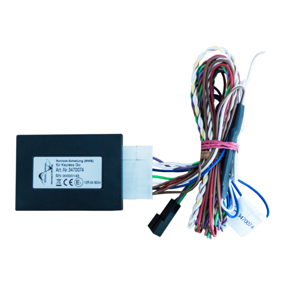
RunLock (MWS)
RunLock
Nur für Fahrzeuge mit Keyless Go!
Only for vehicles with Keyless Go!
Art. Nr. B-339VW02
Skoda
Fabia III (NJ, 2014-)
Kodiaq (2017-)
Octavia III (5E, 2012-2016)
Octavia III (5E) Facelift (2016-2019)
Octavia IV (2019-)
Superb III (3V, 2015-2019)
Karoq (2017-)
Phone:
+49 8061 49518 – 0
Fax:
+49 8061 49518 – 10
VW
Crafter (2017-)
Golf 7 AU (2012-2019)
Golf Sportsvan (2014-)
Passat B8 (3G, 2015-2019)
Passat B8 (3G) Facelift (2019-)
Tiguan (AD1) II Gen. (2016-9/2020)
Tiguan Facelift (9/2020-)
Touran (5T) II Gen. (2015-)
E-Mail:
info@speedsignal.de
Homepage: www.speedsignal.de
facebook:
facebook.com/speedsignal
Advertisement

Summary of Contents for Speedsignal B-339VW02
- Page 1 EINBAUANLEITUNG Installation Guide RunLock (MWS) RunLock Nur für Fahrzeuge mit Keyless Go! Only for vehicles with Keyless Go! Art. Nr. B-339VW02 Fahrzeuge – Vehicles SEAT Skoda Ateca (2016-) Fabia III (NJ, 2014-) Crafter (2017-) Leon III (5F, 2012-2020) Kodiaq (2017-)
-
Page 2: Benötigtes Werkzeug
Ø 12mm Torx Schraubenzieher Ausbauwerkzeug Lötkolben Bohrmaschine Torx screwdriver Removal tool Drill Soldering irons speedsignal GmbH Phone: +49 8061 49518 – 0 E-Mail: info@speedsignal.de Carl-von-Ossietzky-Straße 3 + 7 Fax: +49 8061 49518 – 10 Homepage: www.speedsignal.de D- 83043 Bad Aibling facebook: facebook.com/speedsignal... - Page 3 Übersicht Abgriff - Overview tap A: Abgriff hinter Statrknopf A: KESSY Steuergerät A: KESSY control unit für grüne und weiße Leitung (MQBevo-Plattform) A: Tap behind start button for green and white wire (MQBevo platform) Ergänzungsleitungen einpinnen – Pinning in additional cables Dem mitgelieferten Kabelsatz C-3470078 liegen drei Er- Three supplementary wires are included with the sup- gänzungsleitungen bei.
- Page 4 Abgriffpunkt : KESSY – Tap point : KESSY Jetzt zwei Schrauben an der unteren Abdeckung über Lenksäulenverkleidung entfernen. Zuerst die obere Ab- den Pedalen lösen (siehe Pfeile) und Abdeckung abneh- deckung und anschließend drei Schrauben (je eine links, men. eine rechts und eine auf der Unterseite) lösen und un- Now loosen two screws on the lower cover above the tere Abdeckung entfernen.
- Page 5 Zündleitung I Zündleitung II Ignition wire I Ignition wire II Fahrzeugseitige, violett-blaue Leitung (Pin 19, markiert) Fahrzeugseitige, violette Leitung (Pin 7, markiert) mit mit mitgelieferter, weißer Leitung technisch einwandfrei mitgelieferter, grüner Leitung technisch einwandfrei ver- verbinden. binden. Connect the violet-blue wire on the vehicle side (pin 19, Connect the violet wire on the vehicle side (pin 7, marked) with the supplied white wire in a technically marked) with the supplied green wire in a technically...
- Page 6 Abgriffpunkt : Startknopf MQBevo – Tap point : Start button MQBevo Die benötigte Abgriff für die weiße und grüne Leitung Das Bedienpanel muss ausgebaut werden. The control panel must be removed. bei Fahrzeugen der MQBevo Plattform befindet sich hin- ter dem Start-Stop (Zündungs-) Knopf. The required tap for the white and green wires on MQBevo platform vehicles is located behind the start- stop (ignition) button.
- Page 7 +12 V Spannungsversorgung – Plus and minus supply An geeigneter Stelle am Fahrzeug Masse (PIN 1 am Interface) und Stromversorgung (PIN 7 am Interface) abgreifen. Belegung Interface Die maximale Stromaufnahme des Interfaces beträgt 1 Ampere! At a suitable location on the vehicle, tap the ground (PIN 1 on the interface) and power supply (PIN 7 on the interface).
- Page 8 Pin Belegung Kabelsatz Stecker – Pin Assignment Cable set Connector blau = Verbindung zum Fahrzeug gelb = Verbindung zum Taster blue = connection to vehicle yellow = connection to button Anschlussbelegung 12-poliger Minifit-Stecker Pin assignment 12-pin Minifit connector Ein-/Ausgang Bezeichnung Kabelfarbe Bemerkung Input/Output...
- Page 9 Funktionsprüfung und Inbetriebnahme – Functional test and commissioning Für eine erfolgreiche Aktivierung der Motorweiterlaufschaltung sind folgende Schritte notwendig: 1. Motor starten 2. Handbremse anziehen 3. Manuell Leerlauf einlegen / Automatik auf Stellung „P“ stellen 4. Füße von den Pedalen nehmen 5.
-
Page 10: Warranty Conditions
Es empfiehlt sich, mit dem Fahrzeughersteller oder einer seiner Vertragswerkstätten Kontakt aufzunehmen, um Risiken auszuschließen. speedsignal GmbH guarantees within the legal deadline of 2 years from the original date of purchase that this product is free from defects in material and work- manship as long as this product was installed similar to our installation guide.


Need help?
Do you have a question about the B-339VW02 and is the answer not in the manual?
Questions and answers