
Related Manuals for Pentair WHISPERFLOXF VS


Summary of Contents for Pentair WHISPERFLOXF VS
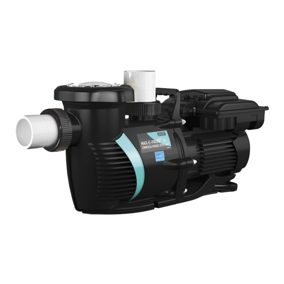
- Page 1 ® WHISPERFLO ® MAX-E-PRO COMMERCIAL VARIABLE SPEED PUMP INSTALLATION AND USER’S GUIDE IMPORTANT SAFETY INSTRUCTIONS READ AND FOLLOW ALL INSTRUCTIONS SAVE THESE INSTRUCTIONS...
-
Page 2: Important Safety Instructions
230 VAC charge even when there is no This guide provides installation and operation instructions for this pump. power to the unit. Consult Pentair with any questions regarding this equipment. • The pump is not submersible. Attention Installer: This guide contains important information about the •... - Page 3 IMPORTANT SAFETY INSTRUCTIONS Mechanical Entrapment: When jewelry, swimsuit, hair decorations, finger, HAZARDOUS PRESSURE: STAND CLEAR OF toe or knuckle is caught in an opening of an outlet or drain cover. This PUMP AND FILTER DURING START UP hazard is present when the drain cover is missing, broken, loose, cracked, Circulation systems operate under high pressure.
-
Page 4: Table Of Contents
CUSTOMER SERVICE / TECHNICAL SUPPORT If you have questions about ordering Pentair replacement parts, and pool products, please contact: Customer Service and Technical Support, USA Sanford, North Carolina (8 A.M. to 4:30 P.M. ET) (8 A.M. to 4:30 P.M. — Eastern/Pacific Times) -
Page 5: Introduction
Determining the optimal settings and programming for • Communicates with most Pentair automation systems your pool may require some trial-and-error. via the Digital Input Wiring Kit (P/N 353129Z- Almond) or RS-485 Automation Wiring Kit (P/N 356324Z - Drive Features Black). -
Page 6: Using The Drive Keypad
USING THE DRIVE KEYPAD Before operating the pump for the first time, the pump’s internal clock and operational schedules must be programmed. Please refer to Setting the Clock and Pump Address and Programming Custom Schedules, page 8, for instructions regarding the programming of this pump for scheduled operation. This pump is capable of maintaining either constant speeds or constant flows. -
Page 7: Installation
4. For most installations Pentair recommends installing a valve on both the pump suction and return lines 4. Be sure to install check valves when plumbing in so that the pump can be isolated during routine parallel with another pump. -
Page 8: Electrical Installation
If these own independent circuit unless the pump is requirements are not met, permanent motor damage operated in tandem with a Pentair salt chlorine may occur. generator. 3. For wiring sizes and general guidelines for proper 3. -
Page 9: External Control Via Rs-485
External Control via RS-485 TO WIRE FOR EXTERNAL CONTROL USING RS-485: The following instructions only apply to pumps manufactured after December 2020. For all other 1. Route the communication cable from the Pump pumps, refer to External Control via Digital Inputs on Com Port (Figure 5) to the control system wiring page 6. -
Page 10: External Control Via Digital Inputs
External Control via Digital Inputs When paired with either the Digital Input Wiring Kit (P/N 353129Z - Almond) or RS-485 Automation Wiring Kit (P/N 356324Z - Black), the pump can be externally controlled by digital input signals. Note: If the pump is manually stopped using the Start/Stop button, the pump will not run until the Start/Stop button is pressed. -
Page 11: Using An External Input Signal
Using an External Input Signal When using an externally supplied low voltage signal for external control, input voltage must be within 5-30V AC/DC. The wiring kit's RED wire is only intended to carry the +24V output signal from the drive and will NOT be used. The +24V signal (RED wire) is output from the drive only and should never be wired to another power supply. -
Page 12: Operation
OPERATION Setting the Clock and Pump Address Programming Custom Schedules When power is first connected to the pump the clock To customize your pump’s schedule, the pump must will blink to indicate that is has not been set. Custom be stopped. Ensure that the Start/Stop LED is not schedules are based on this clock setting, so the clock illuminated. -
Page 13: Program Priorities (Non-External Control)
Programming Custom Schedules Program Priorities (cont.) (Non-External Control) 6. Press “1”. PROGRAM 1 duration will display. The “Duration” parameter LED will begin to blink. See For schedule duration settings, PROGRAMs are Figure 11. prioritized as follows: PROGRAM 1 -> PROGRAM 2 ->... -
Page 14: Priming The Pump
Priming the Pump This pump is shipped with Priming mode ENABLED. Unless the Priming Speed has been modified, the pump will ramp up to 3450 RPM when powered on for the first time, and the Start/Stop button is pressed. Before turning the pump ON, be sure the following conditions are met: 1. -
Page 15: Priming Adjustment
Priming Adjustment This pump is shipped with Priming ENABLED. The pump will ramp up to 3450 RPM when the pump is initially started. Before turning the pump ON: 1. Open filter air relief valve. 2. Open valves. 3. Pool return is completely open and clear of any blockages. 4. -
Page 16: Operating The Pump While Running
Operating the Pump While Running Programming Quick Clean The pump is equipped with a Quick Clean feature, which If power is connected to the pump, pressing any of the can be engaged to temporarily run at higher or lower speeds following buttons referred to in this section could result in the motor starting. -
Page 17: Keypad Lockout
Keypad Lockout Factory Reset The drive can be reset to factory settings if necessary. Keypad lockout will not prevent the motor from A Factory Reset will remove all programmed settings being stopped by pressing the Start/Stop button. If the pump is stopped with the Start/Stop button during Keypad Lockout, it and schedules, except for the clock. -
Page 18: Operating The Pump In Flow Mode
RS-485 Automation Wiring Kit (P/N 356324Z - Black). Flow mode operation is not possible if controlling the pump via RS-485. • A 4-20mA Flowmeter (Pentair recommends P/N 97014-4203KIT) Flow Mode Setup and Configuration Figure 19 Before beginning flow mode setup and configuration, 7. -
Page 19: Adjusting Flow Setting
Flow Mode Setup and Configuration Adjusting Flow Setting (cont.) 12. At the pump, press Display to advance. 1. Use “+” and “-” to increase or decrease the Flow Percentage. This percentage is based on the Note: If the pump displays “LoFlo” or “HiFlo” and high speed set during Flow Mode setup and a percentage other than “100”... -
Page 20: Maintenance
MAINTENANCE DO NOT open the strainer pot if pump fails to prime or if pump has been operating without water in the strainer pot. Pumps operated in these circumstances may experience a build up of vapor pressure and may contain scalding hot water. Opening the pump may cause serious personal injury. -
Page 21: Motor And Drive Care
Always disconnect power to the pump at the circuit breaker and disconnect the digital input cable before servicing the pump. Failure to do so could result in death or serious injury to service people, users or others due to electric shock. Read all servicing instructions before working on the pump. DO NOT open the strainer pot if pump fails to prime or if pump has been operating without water in the strainer pot. -
Page 22: Shaft Seal Replacement
Shaft Seal Replacement Pump Reassembly The Shaft Seal consists of two halves, a rotating spring seal 1. Using a 9/16” wrench, secure the seal plate to the and a fixed ceramic seal. The shaft seal may occasionally motor with the four (4) motor bolts. Tighten to 75-80 become damaged and require replacement. -
Page 23: Replacing The Drive Assembly
Replacing the Drive Assembly TO REMOVE THE EXISTING DRIVE ASSEMBLY: 1. If possible, record your programmed schedule and priming speed before proceeding. 2. Disconnect power to the pump at the circuit breaker. Wait five minutes after disconnecting the power before removing the drive cover. -
Page 24: Troubleshooting
TROUBLESHOOTING Always disconnect power to the pump at the circuit breaker and disconnect the digital input cable before servicing the pump. Failure to do so could result in death or serious injury to serviceman, pool users or others due to electric shock. DO NOT attempt to adjust or service without consulting your dealer or a qualified pool technician. - Page 25 Troubleshooting, (continued) Problem Possible Cause Corrective Action Pump runs without flow. Impeller is loose. Check that pump is spinning by looking at fan on back of motor. If so, check that pump impeller is correctly installed. Air leak. Check plumbing connections and verify they are tight. Clogged or restricted plumbing or strainer basket.
-
Page 26: Faults And Alarms
Faults and Alarms If an alarm is triggered the drive’s LCD screen will display the fault code text and the pump will stop. Disconnect power to the pump and wait until the keypad LEDs have all turned off. At this point, reconnect power to the pump. If the error has not cleared then proper troubleshooting will be required. -
Page 27: Replacement Parts
REPLACEMENT PARTS 19 20 10 11 WhisperFloXF Max-E-ProXF WhisperFloXF Max-E-ProXF Item Description Item Description Part # Part # Part # Part # Drive Kit 358085 358086 Diffuser 400011 Top Cover Kit w/ Screws and Diffuser Screws 353323 358093 358094 Gasket Diffuser O-ring 350336 Motor w/ Fan Shroud... -
Page 28: Technical Data
TECHNICAL DATA Performance Curves QUICK CLEAN 3450 RPM PROGRAM 3 3000 RPM PROGRAM 2 2500 RPM PROGRAM 1 1720 RPM 100 110 120 130 140 150 160 170 180 190 200 210 220 230 240 250 260 270 280 Volumetric Flow Rate in GPM Pump Dimensions (11”) (14.1”) - Page 29 NOTES ® ® WHISPERFLO VS and MAX-E-PRO VS Commercial Variable Speed Pump Installation and User’ s Guide...
- Page 30 NOTES ® ® WHISPERFLO VS and MAX-E-PRO VS Commercial Variable Speed Pump Installation and User’ s Guide...
- Page 31 NOTES ® ® WHISPERFLO VS and MAX-E-PRO VS Commercial Variable Speed Pump Installation and User’ s Guide...
- Page 32 WWW.PENTAIR.COM All indicated Pentair trademarks and logos are property of Pentair. Third party registered and unregistered trademarks and logos are the property of their respective owners. Because we are continuously improving our products and services, Pentair reserves the right to change specifications without prior notice.
Need help?
Do you have a question about the WHISPERFLOXF VS and is the answer not in the manual?
Questions and answers